
Image Science: MTF Measurement & Testing - mtf tester
(a) At what angle will light traveling in air be completely polarized horizontally when reflected from water? (b) From glass?
Due to the sensitivity to the refractive index of the media, diffraction grating can be used as sensor of fluid properties.[31]
4: What angle would the axis of a polarizing filter need to make with the direction of polarized light of intensity 1.00 kW/m2 to reduce the intensity to 10.0W/m2?
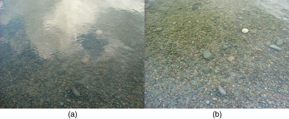
By now you can probably guess that Polaroid sunglasses cut the glare in reflected light because that light is polarized. You can check this for yourself by holding Polaroid sunglasses in front of you and rotating them while looking at light reflected from water or glass. As you rotate the sunglasses, you will notice the light gets bright and dim, but not completely black. This implies the reflected light is partially polarized and cannot be completely blocked by a polarizing filter.
What is diffractiongrating
For typical applications, a reflective grating has ridges or rulings on its surface while a transmissive grating has transmissive or hollow slits on its surface.[6] Such a grating modulates the amplitude of an incident wave to create a diffraction pattern. Some gratings modulate the phases of incident waves rather than the amplitude, and these types of gratings can be produced frequently by using holography.[7]
2: The angle between the axes of two polarizing filters is 45.0 degrees. By how much does the second filter reduce the intensity of the light coming through the first?
A blazed grating is manufactured with grooves that have a sawtooth-shaped cross section, unlike the symmetrical grooves of other gratings. This allows the grating to achieve maximum diffraction efficiency, but in only one diffraction order which is dependent on the angle of the sawtooth grooves, known as the blaze angle. Common uses include specific wavelength selection for tunable lasers, among others.
For a diffraction grating, the relationship between the grating spacing (i.e., the distance between adjacent grating grooves or slits), the angle of the wave (light) incidence to the grating, and the diffracted wave from the grating is known as the grating equation. Like many other optical formulas, the grating equation can be derived by using the Huygens–Fresnel principle,[21] stating that each point on a wavefront of a propagating wave can be considered to act as a point wave source, and a wavefront at any subsequent point can be found by adding together the contributions from each of these individual point wave sources on the previous wavefront.
6: Show that if you have three polarizing filters, with the second at an angle of 45o to the first and the third at an angle of 90.0o to the first, the intensity of light passed by the first will be reduced to 25.0% of its value. (This is in contrast to having only the first and third, which reduces the intensity to zero, so that placing the second between them increases the intensity of the transmitted light.)
While you are undoubtedly aware of liquid crystal displays (LCDs) found in watches, calculators, computer screens, cellphones, flat screen televisions, and other myriad places, you may not be aware that they are based on polarization. Liquid crystals are so named because their molecules can be aligned even though they are in a liquid. Liquid crystals have the property that they can rotate the polarization of light passing through them by 90o. Furthermore, this property can be turned off by the application of a voltage, as illustrated in Figure 12. It is possible to manipulate this characteristic quickly and in small well-defined regions to create the contrast patterns we see in so many LCD devices.
1: What angle is needed between the direction of polarized light and the axis of a polarizing filter to cut its intensity in half?
Fraunhoferdiffraction
Even if the grating equation is derived from a specific grating such as the grating in the right diagram (this grating is called a blazed grating), the equation can apply to any regular structure of the same spacing, because the phase relationship between light scattered from adjacent diffracting elements of the grating remains the same. The detailed diffracted light property distribution (e.g., intensity) depends on the detailed structure of the grating elements as well as on the number of elements in the grating, but it always gives maxima in the directions given by the grating equation.
When groove spacing is less than half the wavelength of light, the only present order is the m = 0 order. Gratings with such small periodicity (with respect to the incident light wavelength) are called subwavelength gratings and exhibit special optical properties. Made on an isotropic material the subwavelength gratings give rise to form birefringence, in which the material behaves as if it were birefringent.
An optical axis diffraction grating, in which the optical axis is spatially and periodically modulated, is also considered either a reflection or transmission phase diffraction grating.
Gratings may be of the 'reflective' or 'transmissive' type, analogous to a mirror or lens, respectively. A grating has a 'zero-order mode' (where the integer order of diffraction m is set to zero), in which a ray of light behaves according to the laws of reflection (like a mirror) and refraction (like a lens), respectively.
Figure 10 illustrates how the component of the electric field parallel to the long molecules is absorbed. An electromagnetic wave is composed of oscillating electric and magnetic fields. The electric field is strong compared with the magnetic field and is more effective in exerting force on charges in the molecules. The most affected charged particles are the electrons in the molecules, since electron masses are small. If the electron is forced to oscillate, it can absorb energy from the EM wave. This reduces the fields in the wave and, hence, reduces its intensity. In long molecules, electrons can more easily oscillate parallel to the molecule than in the perpendicular direction. The electrons are bound to the molecule and are more restricted in their movement perpendicular to the molecule. Thus, the electrons can absorb EM waves that have a component of their electric field parallel to the molecule. The electrons are much less responsive to electric fields perpendicular to the molecule and will allow those fields to pass. Thus the axis of the polarizing filter is perpendicular to the length of the molecule.
Diffractiondiagram
Figure 8 illustrates what happens when unpolarized light is reflected from a surface. Vertically polarized light is preferentially refracted at the surface, so that the reflected light is left more horizontally polarized. The reasons for this phenomenon are beyond the scope of this text, but a convenient mnemonic for remembering this is to imagine the polarization direction to be like an arrow. Vertical polarization would be like an arrow perpendicular to the surface and would be more likely to stick and not be reflected. Horizontal polarization is like an arrow bouncing on its side and would be more likely to be reflected. Sunglasses with vertical axes would then block more reflected light than unpolarized light from other sources.
The times of the paths near the classical reflection site of the mirror are nearly the same, so the probability amplitudes point in nearly the same direction—thus, they have a sizable sum. Examining the paths towards the edges of the mirror reveals that the times of nearby paths are quite different from each other, and thus we wind up summing vectors that cancel out quickly. So, there is a higher probability that light will follow a near-classical reflection path than a path further out. However, a diffraction grating can be made out of this mirror, by scraping away areas near the edge of the mirror that usually cancel nearby amplitudes out—but now, since the photons don't reflect from the scraped-off portions, the probability amplitudes that would all point, for instance, at forty-five degrees, can have a sizable sum. Thus, this lets light of the right frequency sum to a larger probability amplitude, and as such possess a larger probability of reaching the appropriate final point.
17: (a) 2.07 x10⁻² o C/s (b) Yes, the polarizing filters get hot because they absorb some of the lost energy from the sunlight.
Quantum electrodynamics (QED) offers another derivation of the properties of a diffraction grating in terms of photons as particles (at some level). QED can be described intuitively with the path integral formulation of quantum mechanics. As such it can model photons as potentially following all paths from a source to a final point, each path with a certain probability amplitude. These probability amplitudes can be represented as a complex number or equivalent vector—or, as Richard Feynman simply calls them in his book on QED, "arrows".
Diffraction gratings are often used in monochromators, spectrometers, lasers, wavelength division multiplexing devices, optical pulse compressing devices, interferometers,[28] and many other optical instruments.
Find Polaroid sunglasses and rotate one while holding the other still and look at different surfaces and objects. Explain your observations. What is the difference in angle from when you see a maximum intensity to when you see a minimum intensity? Find a reflective glass surface and do the same. At what angle does the glass need to be oriented to give minimum glare?
The diffracted beams corresponding to consecutive orders may overlap, depending on the spectral content of the incident beam and the grating density. The higher the spectral order, the greater the overlap into the next order.
The diffracted light that corresponds to direct transmission for a transmissive diffraction grating or specular reflection[24] for a reflective grating is called the zero order, and is denoted m = 0 {\displaystyle m=0} . The other diffracted light intensity maxima occur at angles θ m {\displaystyle \theta _{m}} represented by non-zero integer diffraction orders m {\displaystyle m} . Note that m {\displaystyle m} can be positive or negative, corresponding to diffracted orders on both sides of the zero-order diffracted beam.
14: If θb is Brewster’s angle for light reflected from the top of an interface between two substances, and θb‘ is Brewster’s angle for light reflected from below, prove that θb + θb‘ = 90o..
In optics, a diffraction grating is an optical grating with a periodic structure that diffracts light, or another type of electromagnetic radiation, into several beams traveling in different directions (i.e., different diffraction angles). The emerging coloration is a form of structural coloration.[1][2] The directions or diffraction angles of these beams depend on the wave (light) incident angle to the diffraction grating, the spacing or periodic distance between adjacent diffracting elements (e.g., parallel slits for a transmission grating) on the grating, and the wavelength of the incident light. The grating acts as a dispersive element. Because of this, diffraction gratings are commonly used in monochromators and spectrometers, but other applications are also possible such as optical encoders for high-precision motion control[3] and wavefront measurement.[4][5]
There is a range of optical effects used in sunglasses. Besides being Polaroid, other sunglasses have coloured pigments embedded in them, while others use non-reflective or even reflective coatings. A recent development is photochromic lenses, which darken in the sunlight and become clear indoors. Photochromic lenses are embedded with organic microcrystalline molecules that change their properties when exposed to UV in sunlight, but become clear in artificial lighting with no UV.
James Gregory (1638–1675) observed the diffraction patterns caused by a bird feather, which was effectively the first diffraction grating (in a natural form) to be discovered, about a year after Isaac Newton's prism experiments.[8] The first human-made diffraction grating was made around 1785 by Philadelphia inventor David Rittenhouse, who strung hairs between two finely threaded screws.[9][10] This was similar to notable German physicist Joseph von Fraunhofer's wire diffraction grating in 1821.[11][12] The principles of diffraction were discovered by Thomas Young[13] and Augustin-Jean Fresnel.[14][15] Using these principles, Fraunhofer was the first to use a diffraction grating to obtain line spectra and the first to measure the wavelengths of spectral lines with a diffraction grating.
An idealized diffraction grating is made up of a set of slits of spacing d {\displaystyle d} , that must be wider than the wavelength of interest to cause diffraction. Assuming a plane wave of monochromatic light of wavelength λ {\displaystyle \lambda } at normal incidence on a grating (i.e., wavefronts of the incident wave are parallel to the grating main plane), each slit in the grating acts as a quasi point wave source from which light propagates in all directions (although this is typically limited to the forward hemisphere from the point source). Of course, every point on every slit to which the incident wave reaches plays as a point wave source for the diffraction wave and all these contributions to the diffraction wave determine the detailed diffraction wave light property distribution, but diffraction angles (at the grating) at which the diffraction wave intensity is highest are determined only by these quasi point sources corresponding the slits in the grating. After the incident light (wave) interacts with the grating, the resulting diffracted light from the grating is composed of the sum of interfering[22] wave components emanating from each slit in the grating; At any given point in space through which the diffracted light may pass, typically called observation point, the path length from each slit in the grating to the given point varies, so the phase of the wave emanating from each of the slits at that point also varies. As a result, the sum of the diffracted waves from the grating slits at the given observation point creates a peak, valley, or some degree between them in light intensity through additive and destructive interference.[23] When the difference between the light paths from adjacent slits to the observation point is equal to an odd integer-multiple of the half of the wavelength, l l ( λ / 2 ) {\displaystyle l(\lambda /2)} with an odd integer l {\displaystyle l} , the waves are out of phase at that point, and thus cancel each other to create the (locally) minimum light intensity. Similarly, when the path difference is a multiple of λ {\displaystyle \lambda } , the waves are in phase and the (locally) maximum intensity occurs. For light at the normal incidence to the grating, the intensity maxima occur at diffraction angles θ m {\displaystyle \theta _{m}} , which satisfy the relationship d sin θ m = m λ {\displaystyle d\sin \theta _{m}=m\lambda } , where θ m {\displaystyle \theta _{m}} is the angle between the diffracted ray and the grating's normal vector, d {\displaystyle d} is the distance from the center of one slit to the center of the adjacent slit, and m {\displaystyle m} is an integer representing the propagation-mode of interest called the diffraction order.
The wavelength dependence in the grating equation shows that the grating separates an incident polychromatic beam into its constituent wavelength components at different angles, i.e., it is angular dispersive. Each wavelength of input beam spectrum is sent into a different direction, producing a rainbow of colors under white light illumination. This is visually similar to the operation of a prism, although the mechanism is very different. A prism refracts waves of different wavelengths at different angles due to their different refractive indices, while a grating diffracts different wavelengths at different angles due to interference at each wavelength.
Another method for manufacturing diffraction gratings uses a photosensitive gel sandwiched between two substrates. A holographic interference pattern exposes the gel, which is later developed. These gratings, called volume phase holography diffraction gratings (or VPH diffraction gratings) have no physical grooves, but instead a periodic modulation of the refractive index within the gel. This removes much of the surface scattering effects typically seen in other types of gratings. These gratings also tend to have higher efficiencies, and allow for the inclusion of complicated patterns into a single grating. A VPH diffraction grating is typically a transmission grating, through which incident light passes and is diffracted, but a VPH reflection grating can also be made by tilting the direction of a refractive index modulation with respect to the grating surface.[27] In older versions of such gratings, environmental susceptibility was a trade-off, as the gel had to be contained at low temperature and humidity. Typically, the photosensitive substances are sealed between two substrates that make them resistant to humidity, and thermal and mechanical stresses. VPH diffraction gratings are not destroyed by accidental touches and are more scratch resistant than typical relief gratings.
Douglas College Physics 1207 Copyright © August 22, 2016 by OpenStax is licensed under a Creative Commons Attribution 4.0 International License, except where otherwise noted.
All we need to solve these problems are the indices of refraction. Air has n1 = 1.00, water has n2 = 1.333, and crown glass has n’2 = 1.520. The equation [latex] \textbf{tan} \;\theta_{b} = \frac{n_2}{n_1} [/latex] can be directly applied to find θb in each case.
Photographs of the sky can be darkened by polarizing filters, a trick used by many photographers to make clouds brighter by contrast. Scattering from other particles, such as smoke or dust, can also polarize light. Detecting polarization in scattered EM waves can be a useful analytical tool in determining the scattering source.
3: If you have completely polarized light of intensity 150 W/m2 what will its intensity be after passing through a polarizing filter with its axis at an 89.0o angle to the light’s polarization direction?
A diffraction grating can create "rainbow" colors when it is illuminated by a wide-spectrum (e.g., continuous) light source. Rainbow-like colors from closely spaced narrow tracks on optical data storage disks such as CDs or DVDs are an example of light diffraction caused by diffraction gratings. A usual diffraction grating has parallel lines (It is true for 1-dimensional gratings, but 2 or 3-dimensional gratings are also possible and they have their applications such as wavefront measurement), while a CD has a spiral of finely spaced data tracks. Diffraction colors also appear when one looks at a bright point source through a translucent fine-pitch umbrella fabric covering. Decorative patterned plastic films based on reflective grating patches are inexpensive and commonplace. A similar color separation seen from thin layers of oil (or gasoline, etc.) on water, known as iridescence, is not caused by diffraction from a grating but rather by thin film interference from the closely stacked transmissive layers.
where n1 is the medium in which the incident and reflected light travel and n2 is the index of refraction of the medium that forms the interface that reflects the light. This equation is known as Brewster’s law, and θb is known as Brewster’s angle, named after the 19th-century Scottish physicist who discovered them.
Diffractionexamples
Light reflected at these angles could be completely blocked by a good polarizing filter held with its axis vertical. Brewster’s angle for water and air are similar to those for glass and air, so that sunglasses are equally effective for light reflected from either water or glass under similar circumstances. Light not reflected is refracted into these media. So at an incident angle equal to Brewster’s angle, the refracted light will be slightly polarized vertically. It will not be completely polarized vertically, because only a small fraction of the incident light is reflected, and so a significant amount of horizontally polarized light is refracted.
Many crystals and solutions rotate the plane of polarization of light passing through them. Such substances are said to be optically active. Examples include sugar water, insulin, and collagen (see Figure 13). In addition to depending on the type of substance, the amount and direction of rotation depends on a number of factors. Among these is the concentration of the substance, the distance the light travels through it, and the wavelength of light. Optical activity is due to the asymmetric shape of molecules in the substance, such as being helical. Measurements of the rotation of polarized light passing through substances can thus be used to measure concentrations, a standard technique for sugars. It can also give information on the shapes of molecules, such as proteins, and factors that affect their shapes, such as temperature and pH.
The grating equation shows that the angles of the diffracted orders only depend on the grooves' period, and not on their shape. By controlling the cross-sectional profile of the grooves, it is possible to concentrate most of the diffracted optical energy in a particular order for a given wavelength. A triangular profile is commonly used. This technique is called blazing. The incident angle and wavelength for which the diffraction is most efficient (the ratio of the diffracted optical energy to the incident energy is the highest) are often called blazing angle and blazing wavelength. The efficiency of a grating may also depend on the polarization of the incident light. Gratings are usually designated by their groove density, the number of grooves per unit length, usually expressed in grooves per millimeter (g/mm), also equal to the inverse of the groove period. The groove period must be on the order of the wavelength of interest; the spectral range covered by a grating is dependent on groove spacing and is the same for ruled and holographic gratings with the same grating constant (meaning groove density or the groove period). The maximum wavelength that a grating can diffract is equal to twice the grating period, in which case the incident and diffracted light are at ninety degrees (90°) to the grating normal. To obtain frequency dispersion over a wider frequency one must use a prism. The optical regime, in which the use of gratings is most common, corresponds to wavelengths between 100 nm and 10 µm. In that case, the groove density can vary from a few tens of grooves per millimeter, as in echelle gratings, to a few thousands of grooves per millimeter.
What is diffractionin physics
Figure 6 shows the effect of two polarizing filters on originally unpolarized light. The first filter polarizes the light along its axis. When the axes of the first and second filters are aligned (parallel), then all of the polarized light passed by the first filter is also passed by the second. If the second polarizing filter is rotated, only the component of the light parallel to the second filter’s axis is passed. When the axes are perpendicular, no light is passed by the second.
3: No light passes through two perfect polarizing filters with perpendicular axes. However, if a third polarizing filter is placed between the original two, some light can pass. Why is this? Under what circumstances does most of the light pass?
Only the component of the EM wave parallel to the axis of a filter is passed. Let us call the angle between the direction of polarization and the axis of a filter θ. If the electric field has an amplitude E, then the transmitted part of the wave has an amplitude Ecosθ (see Figure 7). Since the intensity of a wave is proportional to its amplitude squared, the intensity I of the transmitted wave is related to the incident wave by
where Io is the intensity of the polarized wave before passing through the filter. (The above equation is known as Malus’s law.)
What angle is needed between the direction of polarized light and the axis of a polarizing filter to reduce its intensity by 90.0 %?
The grating equation applies to all these gratings due to the same phase relationship between the diffracted waves from adjacent diffracting elements of the gratings, even if the detailed distribution of the diffracted wave property depends on the detailed structure of each grating.
Diffraction gratings are also used to distribute evenly the frontlight of e-readers such as the Nook Simple Touch with GlowLight.[32]
Since the part of the light that is not reflected is refracted, the amount of polarization depends on the indices of refraction of the media involved. It can be shown that reflected light is completely polarized at a angle of reflection θb, given by
Striated muscle is the most commonly found natural diffraction grating[34] and, this has helped physiologists in determining the structure of such muscle. Aside from this, the chemical structure of crystals can be thought of as diffraction gratings for types of electromagnetic radiation other than visible light, this is the basis for techniques such as X-ray crystallography.
Semiconductor technology today is also used to etch holographically patterned gratings into robust materials such as fused silica. In this way, low stray-light holography is combined with the high efficiency of deep, etched transmission gratings, and can be incorporated into high-volume, low-cost semiconductor manufacturing technology.
Diffractionof waves
This particular description involves many simplifications: a point source, a "surface" that light can reflect off of (thus neglecting the interactions with electrons) and so forth. The biggest simplification is perhaps in the fact that the "spinning" of the probability amplitude arrows is actually more accurately explained as a "spinning" of the source, as the probability amplitudes of photons do not "spin" while they are in transit. We obtain the same variation in probability amplitudes by letting the time at which the photon left the source be indeterminate—and the time of the path now tells us when the photon would have left the source, and thus what the angle of its "arrow" would be. However, this model and approximation is a reasonable one to illustrate a diffraction grating conceptually. Light of a different frequency may also reflect off of the same diffraction grating, but with a different final point.[26]
Polarizing filters have a polarization axis that acts as a slit. This slit passes electromagnetic waves (often visible light) that have an electric field parallel to the axis. This is accomplished with long molecules aligned perpendicular to the axis as shown in Figure 9.
7: When light is reflected at Brewster’s angle from a smooth surface, it is 100% polarized parallel to the surface. Part of the light will be refracted into the surface. Describe how you would do an experiment to determine the polarization of the refracted light. What direction would you expect the polarization to have and would you expect it to be 100 %?
Ordinary pressed CD and DVD media are every-day examples of diffraction gratings and can be used to demonstrate the effect by reflecting sunlight off them onto a white wall. This is a side effect of their manufacture, as one surface of a CD has many small pits in the plastic, arranged in a spiral; that surface has a thin layer of metal applied to make the pits more visible. The structure of a DVD is optically similar, although it may have more than one pitted surface, and all pitted surfaces are inside the disc.[29][30]
To examine this further, consider the transverse waves in the ropes shown in Figure 3. The oscillations in one rope are in a vertical plane and are said to be vertically polarized. Those in the other rope are in a horizontal plane and are horizontally polarized. If a vertical slit is placed on the first rope, the waves pass through. However, a vertical slit blocks the horizontally polarized waves. For EM waves, the direction of the electric field is analogous to the disturbances on the ropes.
SR gratings are named due to its surface structure of depressions (low relief) and elevations (high relief). Originally, high-resolution gratings were ruled by high-quality ruling engines whose construction was a large undertaking. Henry Joseph Grayson designed a machine to make diffraction gratings, succeeding with one of 120,000 lines to the inch (approx. 4,724 lines per mm) in 1899. Later, photolithographic techniques created gratings via holographic interference patterns. A holographic grating has sinusoidal grooves as the result of an optical sinusoidal interference pattern on the grating material during its fabrication, and may not be as efficient as ruled gratings, but are often preferred in monochromators because they produce less stray light. A copying technique can make high quality replicas from master gratings of either type, thereby lowering fabrication costs.
12: Light reflected at 55.6o from a window is completely polarized. What is the window’s index of refraction and the likely substance of which it is made?
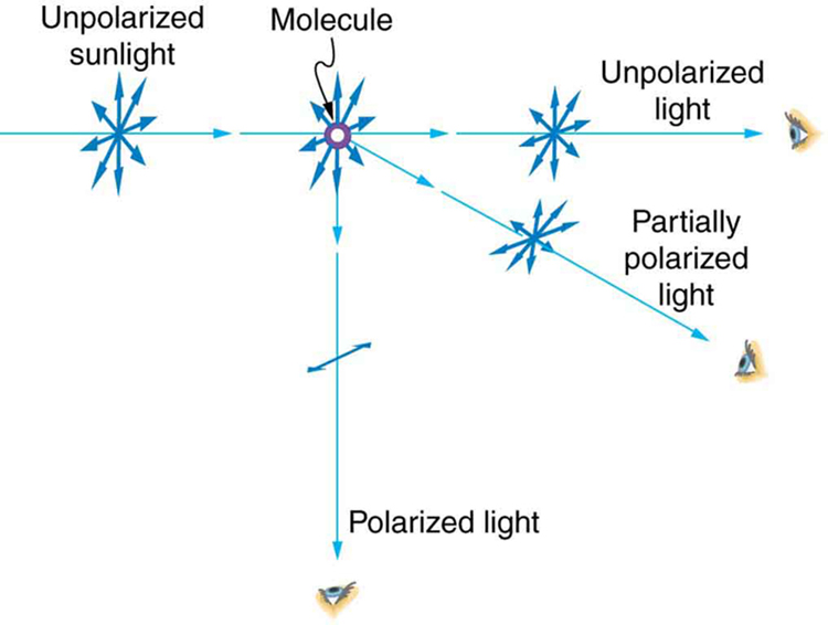
If you hold your Polaroid sunglasses in front of you and rotate them while looking at blue sky, you will see the sky get bright and dim. This is a clear indication that light scattered by air is partially polarized. Figure 11 helps illustrate how this happens. Since light is a transverse EM wave, it vibrates the electrons of air molecules perpendicular to the direction it is traveling. The electrons then radiate like small antennae. Since they are oscillating perpendicular to the direction of the light ray, they produce EM radiation that is polarized perpendicular to the direction of the ray. When viewing the light along a line perpendicular to the original ray, as in Figure 11, there can be no polarization in the scattered light parallel to the original ray, because that would require the original ray to be a longitudinal wave. Along other directions, a component of the other polarization can be projected along the line of sight, and the scattered light will only be partially polarized. Furthermore, multiple scattering can bring light to your eyes from other directions and can contain different polarizations.
Diffraction grating effects are sometimes seen in meteorology. Diffraction coronas are colorful rings surrounding a source of light, such as the sun. These are usually observed much closer to the light source than halos, and are caused by very fine particles, like water droplets, ice crystals, or smoke particles in a hazy sky. When the particles are all nearly the same size they diffract the incoming light at very specific angles. The exact angle depends on the size of the particles. Diffraction coronas are commonly observed around light sources, like candle flames or street lights, in the fog. Cloud iridescence is caused by diffraction, occurring along coronal rings when the particles in the clouds are all uniform in size.[44]
Fresneldiffraction
Depending on how a grating modulates incident light on it to cause the diffracted light, there are the following grating types:[25]
In flat screen LCD televisions, there is a large light at the back of the TV. The light travels to the front screen through millions of tiny units called pixels (picture elements). One of these is shown in Figure 12 (a) and (b). Each unit has three cells, with red, blue, or green filters, each controlled independently. When the voltage across a liquid crystal is switched off, the liquid crystal passes the light through the particular filter. One can vary the picture contrast by varying the strength of the voltage applied to the liquid crystal.
4: Explain what happens to the energy carried by light that it is dimmed by passing it through two crossed polarizing filters.
When a plane light wave is normally incident on a grating of uniform period d {\displaystyle d} , the diffracted light has maxima at diffraction angles θ m {\displaystyle \theta _{m}} given by a special case of the grating equation as sin θ m = m λ d . {\displaystyle \sin \theta _{m}={\frac {m\lambda }{d}}.}
Some everyday electronic components contain fine and regular patterns, and as a result readily serve as diffraction gratings. For example, CCD sensors from discarded mobile phones and cameras can be removed from the device. With a laser pointer, diffraction can reveal the spatial structure of the CCD sensors.[33] This can be done for LCD or LED displays of smart phones as well. Because such displays are usually protected just by transparent casing, experiments can be done without damaging the phones. If accurate measurements are not intended, a spotlight can reveal the diffraction patterns.
Diagram ofdiffractionof light
When the intensity is reduced by 90.0% it is 10% or 0.100 times its original value. That is, I = 0.100 I0. Using this information, the equation I = I0 cos2θ can be used to solve for the needed angle.
(a) On a day when the intensity of sunlight is 1.00 kW/m2, a circular lens 0.200 m in diameter focuses light onto water in a black beaker. Two polarizing sheets of plastic are placed in front of the lens with their axes at an angle of 20.0o. Assuming the sunlight is unpolarized and the polarizers are 100% efficient, what is the initial rate of heating of the water in oC/s, assuming it is 80.0% absorbed? The aluminum beaker has a mass of 30.0 grams and contains 250 grams of water. (b) Do the polarizing filters get hot? Explain.
Suppose you put on two pairs of Polaroid sunglasses with their axes at an angle of 15.0o. How much longer will it take the light to deposit a given amount of energy in your eye compared with a single pair of sunglasses? Assume the lenses are clear except for their polarizing characteristics.
Polaroid sunglasses are familiar to most of us. They have a special ability to cut the glare of light reflected from water or glass as shown in the figure below. Polaroids have this ability because of a wave characteristic of light called polarization. What is polarization? How is it produced? What are some of its uses? The answers to these questions are related to the wave character of light.
The Sun and many other light sources produce waves that are randomly polarized (see Figure 4). Such light is said to be unpolarized because it is composed of many waves with all possible directions of polarization. Polaroid materials, invented by the founder of Polaroid Corporation, Edwin Land, act as a polarizing slit for light, allowing only polarization in one direction to pass through. Polarizing filters are composed of long molecules aligned in one direction. Thinking of the molecules as many slits, analogous to those for the oscillating ropes, we can understand why only light with a specific polarization can get through. The axis of a polarizing filter is the direction along which the filter passes the electric field of an EM wave (see Figure 5).
A fairly large angle between the direction of polarization and the filter axis is needed to reduce the intensity to 10.0% of its original value. This seems reasonable based on experimenting with polarizing films. It is interesting that, at an angle of 45o, the intensity is reduced to 50% of its original value (as you will show in this section’s Problems & Exercises). Note that 71.6o is 18.4o from reducing the intensity to zero, and that at an angle of 18.4o the intensity is reduced to 90.0% of its original value (as you will also show in Problems & Exercises), giving evidence of symmetry.
In a standard pressed vinyl record when viewed from a low angle perpendicular to the grooves, a similar but less defined effect to that in a CD/DVD is seen. This is due to viewing angle (less than the critical angle of reflection of the black vinyl) and the path of the light being reflected due to this being changed by the grooves, leaving a rainbow relief pattern behind.
5: When particles scattering light are much smaller than its wavelength, the amount of scattering is proportional to 1/ λ4. Does this mean there is more scattering for small λ than large λ? How does this relate to the fact that the sky is blue? Hint: red light has a wavelength of about 650 nm while blue light has a wavelength of about 400 nm.
Most commonly confused with diffraction gratings are the iridescent colors of peacock feathers, mother-of-pearl, and butterfly wings. Iridescence in birds,[35] fish[36] and insects[35][37] is often caused by thin-film interference rather than a diffraction grating. Diffraction produces the entire spectrum of colors as the viewing angle changes, whereas thin-film interference usually produces a much narrower range. The surfaces of flowers can also create a diffraction, but the cell structures in plants are usually too irregular to produce the fine slit geometry necessary for a diffraction grating.[38] The iridescence signal of flowers is thus only appreciable very locally and hence not visible to man and flower visiting insects.[39][40] However, natural gratings do occur in some invertebrate animals, like the peacock spiders,[41] the antennae of seed shrimp, and have even been discovered in Burgess Shale fossils.[42][43]
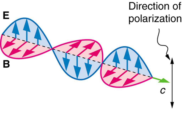
Light is one type of electromagnetic (EM) wave. As noted earlier, EM waves are transverse waves consisting of varying electric and magnetic fields that oscillate perpendicular to the direction of propagation (see Figure 2). There are specific directions for the oscillations of the electric and magnetic fields. Polarization is the attribute that a wave’s oscillations have a definite direction relative to the direction of propagation of the wave. (This is not the same type of polarization as that discussed for the separation of charges.) Waves having such a direction are said to be polarized. For an EM wave, we define the direction of polarization to be the direction parallel to the electric field. Thus we can think of the electric field arrows as showing the direction of polarization, as in Figure 2.
13: (a) Light reflected at 62.5o from a gemstone in a ring is completely polarized. Can the gem be a diamond? (b) At what angle would the light be completely polarized if the gem was in water?
Glass and plastic become optically active when stressed; the greater the stress, the greater the effect. Optical stress analysis on complicated shapes can be performed by making plastic models of them and observing them through crossed filters, as seen in Figure 14. It is apparent that the effect depends on wavelength as well as stress. The wavelength dependence is sometimes also used for artistic purposes.
For the probability that a certain event will happen, one sums the probability amplitudes for all of the possible ways in which the event can occur, and then takes the square of the length of the result. The probability amplitude for a photon from a monochromatic source to arrive at a certain final point at a given time, in this case, can be modeled as an arrow that spins rapidly until it is evaluated when the photon reaches its final point. For example, for the probability that a photon will reflect off of a mirror and be observed at a given point a given amount of time later, one sets the photon's probability amplitude spinning as it leaves the source, follows it to the mirror, and then to its final point, even for paths that do not involve bouncing off of the mirror at equal angles. One can then evaluate the probability amplitude at the photon's final point; next, one can integrate over all of these arrows (see vector sum), and square the length of the result to obtain the probability that this photon will reflect off of the mirror in the pertinent fashion. The times these paths take are what determines the angle of the probability amplitude arrow, as they can be said to "spin" at a constant rate (which is related to the frequency of the photon).
A new technology for grating insertion into integrated photonic lightwave circuits is digital planar holography (DPH). DPH gratings are generated in computer and fabricated on one or several interfaces of an optical waveguide planar by using standard micro-lithography or nano-imprinting methods, compatible with mass-production. Light propagates inside the DPH gratings, confined by the refractive index gradient, which provides longer interaction path and greater flexibility in light steering.
It can be shown that if the plane wave is incident at angle θ i {\displaystyle \theta _{i}} relative to the grating normal, in the plane orthogonal to the grating periodicity, the grating equation becomes sin θ i + sin θ m = m λ d , {\displaystyle \sin \theta _{i}+\sin \theta _{m}={\frac {m\lambda }{d}},} which describes in-plane diffraction as a special case of the more general scenario of conical, or off-plane, diffraction described by the generalized grating equation: sin θ i + sin θ m = m λ d sin γ , {\displaystyle \sin \theta _{i}+\sin \theta _{m}={\frac {m\lambda }{d\sin \gamma }},} where γ {\displaystyle \gamma } is the angle between the direction of the plane wave and the direction of the grating grooves, which is orthogonal to both the directions of grating periodicity and grating normal. Various sign conventions for θ i {\displaystyle \theta _{i}} , θ m {\displaystyle \theta _{m}} and m {\displaystyle m} are used; any choice is fine as long as the choice is kept through diffraction-related calculations. When solved for diffracted angle at which the diffracted wave intensity are maximized, the equation becomes θ m = arcsin ( sin θ i − m λ d sin γ ) . {\displaystyle \theta _{m}=\arcsin \!\left(\sin \theta _{i}-{\frac {m\lambda }{d\sin \gamma }}\right).}
Another interesting phenomenon associated with polarized light is the ability of some crystals to split an unpolarized beam of light into two. Such crystals are said to be birefringent (see Figure 15). Each of the separated rays has a specific polarization. One behaves normally and is called the ordinary ray, whereas the other does not obey Snell’s law and is called the extraordinary ray. Birefringent crystals can be used to produce polarized beams from unpolarized light. Some birefringent materials preferentially absorb one of the polarizations. These materials are called dichroic and can produce polarization by this preferential absorption. This is fundamentally how polarizing filters and other polarizers work. The interested reader is invited to further pursue the numerous properties of materials related to polarization.
If a polarizing filter reduces the intensity of polarized light to 50.0 % of its original value, by how much are the electric and magnetic fields reduced?
5: At the end of Example 1, it was stated that the intensity of polarized light is reduced to 90.0% of its original value by passing through a polarizing filter with its axis at an angle of 18.4 degrees to the direction of polarization. Verify this statement.
In the 1860s, state-of-the-art diffraction gratings with small groove period (d) were manufactured by Friedrich Adolph Nobert (1806–1881) in Greifswald;[16] then the two Americans Lewis Morris Rutherfurd (1816–1892) and William B. Rogers (1804–1882) took over the lead.[17][18] By the end of the 19th century, the concave gratings of Henry Augustus Rowland (1848–1901) were the best available.[19][20]


 Ms.Cici
 8618319014500