
How to Use a Line Laser Level (Step-by-Step) - straight line laser pen
Multiphoton microscopy principle
Multi-photon excitation (MPE) microscopy plays a growing role among microscopical techniques utilized for studying biological matter. In conjunction with confocal microscopy it can be considered the imaging workhorse of life science laboratories. Its roots can be found in a fundamental work written by Maria Goeppert Mayer more than 70 years ago. Nowadays, 2PE and MPE microscopes are expected to increase their impact in areas such biotechnology, neurobiology, embryology, tissue engineering, materials science where imaging can be coupled to the possibility of using the microscopes in an active way, too. As well, 2PE implementations in noninvasive optical bioscopy or laser-based treatments point out to the relevance in clinical applications. Here we report about some basic aspects related to the phenomenon, implications in three-dimensional imaging microscopy, practical aspects related to design and realization of MPE microscopes, and we only give a list of potential applications and variations on the theme in order to offer a starting point for advancing new applications and developments.
MPE simplified optical schemes. Descanned (red dot) and non-descanned (blue dot) schemes for 2PE microscopy. Due to the confinement of the excitation process when operating in non-descanned mode the collection efficiency in depth is increased as shown by the two side views from the very same thick scattering sample (Courtesy of Mark Cannel and Christian Soeller; image inset courtesy of Ammasi Periasamy).
MPE simplified optical pathways. In the MPE optical pathways the emission pinhole is removed since the only emitted light reaching the sensor is coming from the currently point scanned volume in the sample. No other fluorescence signal is produced elsewhere.
Optical sectioning using 2PE autofluorescence. 2PE optical sectioning of Colpoda maupasi resting cysts, 21–32 μm average dimensions. Encystment is particularly widespread in species living in ephemeral fresh-water puddles and is induced by exhaustion of the food and drying out. The resulting images have been obtained at LAMBS-MicroScoBio exploiting autofluorescence primed using 740 nm excitation. A Chameleon-XR ultrafast Ti-Sapphire laser (Coherent Inc., USA) and a Nikon PCM2000 confocal scanning head have been used [34]. Linear frame dimension is 70 μm, z steps have been performed every 0.5 μm, and not all the optical sections are imaged.
The useful numerical aperture of the objective and therefore the resolving power would be reduced by the reflection described above. The numerical aperture of an objective is also dependent, to a certain degree, upon the amount of correction for optical aberration. Highly corrected objectives tend to have much larger numerical apertures for the respective magnification as illustrated in Table 1.
Erin E. Wilson and Michael W. Davidson - National High Magnetic Field Laboratory, 1800 East Paul Dirac Dr., The Florida State University, Tallahassee, Florida, 32310.
Now, even if the quantum-mechanical selection rules for MPE differ from those for one-photon excitation, several common fluorescent molecules can be used. Unfortunately, the knowledge of 1PE cross-section for a specific fluorescent molecule does not allow any quantitative prediction of the two-photon trend. The only "rule of thumb" that one can use states that a 2PE cross-section peak can be expected at a 2 folds wavelength with respect to the 1PE case. Table 1 summarises the excitation properties of some popular fluorescent molecules under 2PE regime.
It is important, first of all, to know that the objective and tube lens do not image a point in the object (for example, a minute hole in a metal foil) as a bright disk with sharply defined edges, but as a slightly blurred spot surrounded by diffraction rings, called Airy disks (see Figure 3(a)). Three-dimensional representations of the diffraction pattern near the intermediate image plane are known as the point-spread function (Figure 3(b)). An Airy disk is the region enclosed by the first minimum of the airy pattern and contains approximately 84 percent of the luminous energy, as depicted in Figure 3(c). The point-spread function is a three-dimensional representation of the Airy disk.
Resolution can be calculated according to the famous formula introduced by Ernst Abbe in the late 19th Century, and represents a measure of the image sharpness of a light microscope: Resolutionx,y = λ / 2[η • sin(α)](2) Resolutionz = 2λ / [η • sin(α)]2(3) where λ is the wavelength of light, η represents the refractive index of the imaging medium as described above, and the combined term η • sin(α) is known as the objective numerical aperture (NA). Objectives commonly used in microscopy have a numerical aperture that is less than 1.5, restricting the term α in Equations (2) and (3) to less than 70 degrees (although new high-performance objectives closely approach this limit). Therefore, the theoretical resolution limit at the shortest practical wavelength (approximately 400 nanometers) is around 150 nanometers in the lateral dimension and approaching 400 nanometers in the axial dimension when using an objective having a numerical aperture of 1.40. Thus, structures that lie closer than this distance cannot be resolved in the lateral plane using a microscope. Due to the central significance of the interrelationship between the refractive index of the imaging medium and the angular aperture of the objective, Abbe introduced the concept of numerical aperture during the course of explaining microscope resolution. The diffraction rings in the Airy disk are caused by the limiting function of the objective aperture such that the objective acts as a hole, behind which diffraction rings are found. The higher the aperture of the objective and of the condenser, the smaller d0 will be. Thus, the higher the numerical aperture of the total system, the better the resolution. One of the several equations related to the original Abbe formula that have been derived to express the relationship between numerical aperture, wavelength, and resolution is: Resolutionx,y or d0 = 1.22λ / [NAObj + NACon](4) Where λ is the imaging wavelength of light, NACon is the condenser numerical aperture, and NAObj equals the objective numerical aperture. The factor 1.22 has been taken from the calculation for the case illustrated in Figure 4 for the close approach of two Airy disks where the intensity profiles have been superimposed. If the two image points are far away from each other, they are easy to recognize as separate objects. However, when the distance between the Airy disks is increasingly reduced, a limit point is reached when the principal maximum of the second Airy disk coincides with the first minimum of the first Airy disk. The superimposed profiles display two brightness maxima that are separated by a valley. The intensity in the valley is reduced by approximately 20 percent compared with the two maxima. This is just sufficient for the human eye to see two separate points, a limit that is referred to as the Rayleigh criterion. A comparison may help to make this easier to understand. It is most unlikely that a telephone cable would be used for the electronic transfer of the delicate sound of a violin, since the bandwidth of this medium is very restricted. Much better results are obtained if high-quality microphones and amplifiers are used, the frequency range of which is identical to the human range of hearing. In music, information is contained in the medium sound frequencies; however, the fine nuances of sound are contained in the high overtones. In the microscope, the subtleties of a structure are coded into the diffracted light. If you want to see them in the imaging space behind the objective, you must make sure that they are first gathered by the objective. This becomes easier with a higher aperture angle and thus an increased numerical aperture. The numerical aperture of objectives increases with the magnification up to about 40x (see Tables 1 and 2), but levels off between 1.30 and 1.40 (depending upon the degree of aberration correction) for oil immersion versions. Presented in Table 2 are the calculated values for the resolution of objectives typically used in research and teaching laboratories. The point-to-point resolution at the specimen, d0, is listed in the table along with the magnified size of the image (D0) in the intermediate eyepiece plane (using green light of 550 nanometer wavelength). Also in the table, the value n represents the number of resolved pixels if they are organized in a linear array along the field diameter of 20 millimeters (20 millimeters/D0). Resolution for Selected Objectives Objective/NA d0(μm) D0(μm) n 0.5x / 0.15 2.2 11.2 1786 10x / 0.30 1.1 11.2 1786 20x / 0.50 0.7 13.4 1493 40x / 0.75 0.45 17.9 1117 40x / 1.30 (oil) 0.26 10.3 1942 63x / 1.40 (oil) 0.24 15.1 1325 100x / 1.30 (oil) 0.26 25.8 775 Table 2 You should not try to increase the overall magnification of a microscope by using eyepieces providing a high additional magnification (for example, 16x, 20x or 25x) or other optical after-burners if the objective does not supply enough pixels at a low numerical aperture. On the other hand, you will miss subtle nuances if the objective projects very fine details onto the intermediate image, and you are using an eyepiece with a low magnification. In order to observe fine specimen detail in the optical microscope, the minute features present in the specimen must be of sufficient contrast and project an intermediate image at an angle that is somewhat larger than the angular resolving power of the human eye. As previously mentioned, the overall combined magnification (objective and eyepiece) of a microscope should be higher than 500x, but less than 1000x the objective aperture. This value is known as the range of the useful magnification. In day-to-day routine observations, many microscopists do not attempt to achieve the highest image resolution that is possible with their equipment. The resolving power of a microscope is the most important feature of the optical system and influences the ability to distinguish between fine details of a particular specimen. The primary factor in determining resolution is the objective numerical aperture, but resolution is also dependent upon the type of specimen, coherence of illumination, degree of aberration correction, and other factors such as contrast-enhancing methodology either in the optical system of the microscope or in the specimen itself. back to top ^Practical Hints to Increase Resolving Power Modern microscope objectives permit the theoretical resolving power to be realized in practice provided that suitable specimens are being observed. However, there are several hints that can be followed to ensure success. These are listed below. Are the objective and specimen clean? A fingerprint on the front lens of an air objective may be sufficient to affect the high-contrast image reproduction of a specimen as a result of unwanted scattered light. The same caveats apply to immersion objectives that are soiled with residues of resin or emulsions (such as oil and water). In these cases, careful cleaning of the objective front lens element using a soft cloth and lens cleaner or pure ethanol should alleviate problems. Do the cover slips have the correct thickness? It is of critical importance that cover slips matched to objectives of high aperture (greater than 0.65) have the standard thickness of 170 micrometers due to the fact that cover slip thickness is taken into consideration when the objectives are designed. Therefore, if a cover slip of different thickness (less than 165 or more than 175 micrometers) is used, the quality of the optical image visibly suffers. In general, the rule of thumb for objectives having a numerical aperture of 0.7 or higher is that they can tolerate a variation of 10 micrometers, whereas lower numerical aperture objectives (0.3 to 0.7) can tolerate a higher level of deviation, usually up to 30 micrometers. Are you using the correct immersion oil? All objectives having a numerical aperture greater than 0.95 are designed for use with immersion media (usually oil of refractive index 1.515). Immersion oil is free of polychlorinated biphenyls and exhibits hardly any autofluorescence. The image will be markedly impaired if air bubbles are introduced into the immersion layer, so oil must be carefully applied to avoid bubbles. Air bubbles can be readily visualized by removing the eyepiece and examining the objective rear focal plane through the microscope observation tubes (or using a Bertrand lens). If air bubbles are observed, the objective and specimen slide should be cleaned and the oil carefully re-applied. Contributing Authors Rudi Rottenfusser - Zeiss Microscopy Consultant, 46 Landfall, Falmouth, Massachusetts, 02540. Erin E. Wilson and Michael W. Davidson - National High Magnetic Field Laboratory, 1800 East Paul Dirac Dr., The Florida State University, Tallahassee, Florida, 32310. Back to Microscopy Basics
Equation (2) reflects the fact that when a set of two-dimensional images is acquired at various focus position and under certain conditions, in principle, one can recover the 3D shape of the object, described by the intensive parameter I, by solving the above set of equations and finding the best estimate for I, slice by slice. By this procedure, unwanted light can be computationally removed combining the image data from a stack of "k" images. Such an operation can be optically performed using some physical stratagems that are behind confocal and MPE/2PE scanning microscopy.
The diffraction rings in the Airy disk are caused by the limiting function of the objective aperture such that the objective acts as a hole, behind which diffraction rings are found. The higher the aperture of the objective and of the condenser, the smaller d0 will be. Thus, the higher the numerical aperture of the total system, the better the resolution. One of the several equations related to the original Abbe formula that have been derived to express the relationship between numerical aperture, wavelength, and resolution is:
two-photon excitation microscopy
In confocal microscopy, the observed image is built up, scanning the sample point by point, by adding information from x-y-z sampled regions. The price to pay, or the main drawback, is that image formation is not as immediate as widefield techniques in which the whole image is acquired at the same time. This is due to the fact that in confocal microscopy the specimen is sequentially illuminated point by point and at the same time all is masked but the illuminated in-focus regions for providing return light to the detector. As shown in figure 3 an illumination and a detection pinhole are placed in the optical pathway. The detection pinhole – the mask – is placed in front of the detector at a plane that is conjugate to the in-focus or "j" plane, such that the illumination spot and the pinhole aperture are simultaneously focused at the same specimen volume. This coincidence of the illumination and detected volume is responsible for confocality. The final effect of such an optical implementation is that out-of-focus contributions are excluded from the detector surface and the observed image, Oj, is close to the true distribution of the fluorescence intensity I, plane by plane during the x-y-z scanning operations. This allows performing optical sectioning.
Two-photon microscopy
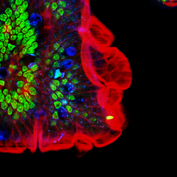
Multiple fluorescence 2PE imaging. 2PE multiple fluorescence image from a 16 μm cryostat section of mouse intestine stained with a combination of fluorescent stains (F-24631, Molecular Probes). Alexa Fluor 350 wheat germ agglutinin, a blue-fluorescent lectin, was used to stain the mucus of goblet cells. The filamentous actin prevalent in the brush border was stained with red-fluorescent Alexa Flu or 568 phalloidin. Finally, the nuclei were stained with SYTOX ® Green nucleic acid stain. Imaging has been performed at 780 nm, 100 x 1.4 NA Leica objective, using a Chameleon XR ultrafast Ti-Sapphire laser (Coherent Inc., USA) coupled at LAMBS-MicroScoBio with a Spectral Confocal Laser Scanning Microscope, Leica SP2-AOBS.
are dimensionless axial and radial coordinates, respectively, normalized to the wavelength. Now, the intensity of fluorescence distribution within the focal region has a I(u, v) behaviour for the 1PE case [31]. In case of 2PE one has to consider a double wavelength and a square behaviour, i.e. I2(u/2, v/2). As compared with the 1PE case, the 2PE emission intensity distribution is axially confined.
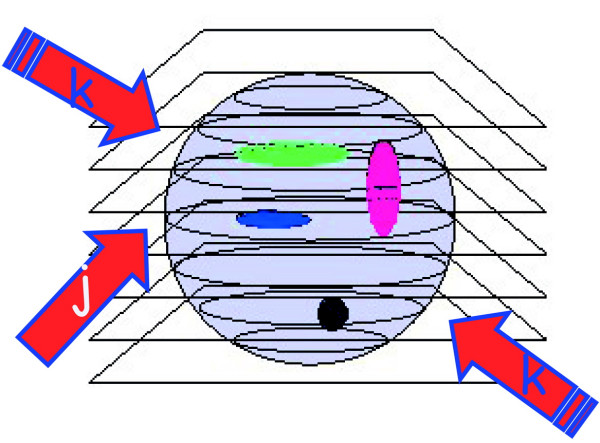
The possibility of the three-dimensional reconstruction of the volume distribution of intensive parameters, as fluorescence emission, from biological systems is one of the most powerful properties of the optical microscope. To collect optical slices from a three-dimensional object the so-called optical sectioning [3,11] technique is used as depicted in figure 2. It is essentially based on a fine z stepping either of the objective or of the sample stage, coupled with the usual x-y image capturing. The synchronous x-y-z scanning allows the collection of a set of two-dimensional images, which are somehow affected by signal cross talk from other planes from the sample. In fact, the observed image Oj, obtainable when positioning the geometrical focus of the lens at a certain plane" j "within the specimen, is produced by the true fluorescence distribution Ij at plane "j", distorted by the microscope in some way that can be described by a function S, plus differently distorted contributions from adjacent "k" planes positioned above and below the actual plane, and noise N. Using a convenient and appropriate formalism one has:
where J0 is the 0th order Bessel function, ρ is a radial coordinate in the pupil plane, n is the refractive index of the medium between the lens and the specimen, (α) is the semi-angle of aperture of the lens [31],
The authors dedicate this work to Osamu Nakamura, a pioneer in 2PE, who passed away on 23 Jan 2005 at Handai Hospital, Japan. AD dedicates this work to Mario Arace and is still using his oscilloscope, purchased in 1978, in the lab. The first Italian 2PE architecture realized at LAMBS of the University of Genoa has been supported by INFM grants. LAMBS-MicroScoBio is currently granted by IFOM (Istituto FIRC di Oncologia Molecolare, FIRC Institute of Molecular Oncology, Milan, Italy) and Fondazione San Paolo (Torino, Italy). LAMBS joins the NANOMED Italian Research Program. MicroScoBio is a Research Center of the University of Genoa on Correlative Microscopy and Spectroscopy with applications in Biomedicine and Oncology, Genoa, Italy. IFOM is the FIRC Foundation on Molecular Oncology, Milan, Italy. LAMBS is a multicenter Laboratory for Advanced Microscopy, Bioimaging and Spectroscopy http://www.lambs.it.
Are the objective and specimen clean? A fingerprint on the front lens of an air objective may be sufficient to affect the high-contrast image reproduction of a specimen as a result of unwanted scattered light. The same caveats apply to immersion objectives that are soiled with residues of resin or emulsions (such as oil and water). In these cases, careful cleaning of the objective front lens element using a soft cloth and lens cleaner or pure ethanol should alleviate problems.
Confocal optical pathways. An illumination and a detection pinhole are placed in the optical pathway. The detection pinhole – the mask – is placed in front of the detector at a plane that is conjugate to the in-focus or "j" plane, such that the illumination spot and the pinhole aperture are simultaneously focused at the same specimen volume. This coincidence of the illumination and detected volume is responsible for confocality. The illumination pinhole allows to perform pointlike scanning.
Optical sectioning scheme. A three-dimensional sample can be sketched as a series of optical slices. Let's call slice j the one containing the geometrical focus of the objective and refer to the adjacent planes as k slices. The sample contains a three-dimensional distribution of fluorescently labelled molecules whose intensity distribution is I, slice by slice. The thickness of each optical slice is approximately one half of the axial resolution, say ≈λ/2.
Multi photonmicroscopy
Now, the most interesting aspect is that the excitation power falls off as the square of the distance from the lens focal point, within the approximation of a conical illumination geometry [31]. In practice this means that the square relationship between the excitation power and the fluorescence intensity brings about the fact that 2PE falls off as the fourth power of distance from the focal point of the objective. This fact implies that those molecules away from the focal region of the objective lens do not contribute to the image formation process and are not affected by photobleaching or phototoxicity. Since these molecules are not involved in the excitation process, a confocal-like effect is obtained without the necessity of a confocal pinhole. It is immediately evident that in this case the optical sectioning effect is obtained in a physically different way with respect to the confocal case. Accordingly the optical set-up is simplified, under some aspects, see figure 4.
The resolution of an optical microscope is defined as the smallest distance between two points on a specimen that can still be distinguished as two separate entities. Resolution is directly related to the useful magnification of the microscope and the perception limit of specimen detail, though it is a somewhat subjective value in microscopy because at high magnification, an image may appear out of focus but still be resolved to the maximum ability of the objective and assisting optical components. Due to the wave nature of light and the diffraction associated with these phenomena, the resolution of a microscope objective is determined by the angle of light waves that are able to enter the front lens and the instrument is therefore said to be diffraction limited. This limit is purely theoretical, but even a theoretically ideal objective without any imaging errors has a finite resolution.
Figure 5 and figure 6 show the differences in terms of excitation-emission process between confocal and multiphoton schemes, respectively. The consequences of the spatial confinement of the MPE result in a consequent confinement of the emitted fluorescence: in the confocal case all the molecules within the double cone of excitation are involved in the light-matter interaction while in the MPE case such interaction is restricted to a small volume centred at the geometrical focus of the objective. The immediate consequence is that a 2PE microscope is an intrinsically three-dimensional image formation system. This fact has also very important consequences on the photobleaching processes. So far, in the 2PE case no fluorescence has to be removed from the detection pathway since fluorescence can exclusively come from a small focal volume that has a capacity of the order of fraction of femtoliter. In fact, in 2PE over 80% of the total intensity of fluorescence comes from a 700–1000 nm thick region about the focal point for objectives with numerical apertures in the range from 1.2 to 1.4 [30]. The fact that the background signal coming from adjacent planes tends to zero produces a sort of compensation for the reduced spatial resolution due to the utilization of a wavelength that is twice with respect to the 1PE case, as shown in figure 7. On the other hand, the utilisation of infrared wavelengths instead of UV-visible ones allows achieving a deeper penetration than in conventional case [32]. This is due to the fact that the scattering effect is proportional to the inverse fourth power of the wavelength. Thus the longer wavelengths used in 2PE, or in general in MPE, will be scattered less than the ultraviolet-visible wavelengths used for conventional excitation allowing to reach fluorescence targets in depth within thick samples (approx. 1 mm). It has been shown that two-photon fluorescence images can be obtained throughout almost the entire grey matter of the mouse neocortex by using optically amplified femtosecond pulses. The achieved imaging depth approaches the theoretical limit set by excitation of out-of-focus fluorescence [33]. The fluorescence light emitted, on the way back, can be more efficiently collected using a large area detector since it can uniquely come from the sub-femtoliter 2PE volume of event.
3D and 2D fluorescence projections. Pictorial representation of the 3D and 2D projections of multiple fluorescence from a marine sponge, Chondrilla nucula. The specimen has been loaded with Alexa 488 fluorescent molecules specific aminobutirric acid (GABA) emitting in green, DAPI for nuclear DNA for the blu component. Red signals are due to the autofluorescence from symbiontic bacteria contamination. Imaging has been perfomed using a Chameleon XR ultrafast Ti-Sapphire laser (Coherent Inc., USA) coupled at LAMBS-MicroScoBio with a Spectral Confocal Laser Scanning Microscope, Leica SP2-AOBS. (Sample availability and preparation, courtesy of Renata Manconi, University of Sassari, Roberto Pronzato and Lorenzo Gallus, University of Genoa).
MPE fluorescence emission distribution. Confinement of the emission process, in green, under red 2PE. Under 2PE the only molecules excited are those confined in a small subfemtoliter volume at the illumination beam focus position. This is particularly relevant for the photobleaching process that is globally reduced with respect to the 1PE case. The capacity of the volume can be approximatively calculated by using the resolution parameters of the optical system, since they are indicators of the volume containing the maximum photon density. This is valid only for non saturated processes. Under saturation of fluorescence beam intensity plays an important role in the emission shape and optical resolution.
One way of increasing the optical resolving power of the microscope is to use immersion liquids between the front lens of the objective and the cover slip. Most objectives in the magnification range between 60x and 100x (and higher) are designed for use with immersion oil. Good results have been obtained with oil that has a refractive index of n = 1.51, which has been precisely matched to the refractive index of glass. All reflections on the path from the object to the objective are eliminated in this way. If this trick were not used, reflection would always cause a loss of light in the cover slip or on the front lens in the case of large angles (Figure 2).
A comparison may help to make this easier to understand. It is most unlikely that a telephone cable would be used for the electronic transfer of the delicate sound of a violin, since the bandwidth of this medium is very restricted. Much better results are obtained if high-quality microphones and amplifiers are used, the frequency range of which is identical to the human range of hearing. In music, information is contained in the medium sound frequencies; however, the fine nuances of sound are contained in the high overtones. In the microscope, the subtleties of a structure are coded into the diffracted light. If you want to see them in the imaging space behind the objective, you must make sure that they are first gathered by the objective. This becomes easier with a higher aperture angle and thus an increased numerical aperture.
Two-photon excitation of fluorescent molecules is a non-linear process related to the simultaneous absorption of two photons whose total energy equals the energy required for the more familiar one-photon excitation (1PE) [29]. The excitation process of a fluorescent molecule under 1PE typically requires photons in the ultraviolet or blue/green spectral range. Under sufficiently intense illumination, usually provided by a laser source, the very same process, i.e. excitation of a fluorescent molecule from the ground to the excited state, can take place in the infrared spectral range. This situation is illustrated in figure 1 using a Perrin-Jablonski diagram: the sum of the energies of the "two" infrared photons colliding with the very same molecule has to be greater than the energy gap between the molecule's ground and excited states. Since 2PE excitation requires at least two statistically "independent" photons for each excitation process, its rate depends on the square power of the instantaneous intensity. 3PE and higher photon excitation is also possible. This implies that deep ultraviolet (UV) microscopy can be performed without having the disadvantages related to UV-matter interactions, i.e. polymerization or temperature effects. However, our treatment will be mainly conducted in terms of 2PE for sake of simplicity but any step can be extended to MPE.
Observers will miss fine nuances in the image if the objective projects details onto the intermediate image plane that are smaller than the resolving power of the human eye (a situation that is typical at low magnifications and high numerical apertures). The phenomenon of empty magnification will occur if an image is enlarged beyond the physical resolving power of the images. For these reasons, the useful magnification to the observer should be optimally above 500 times the numerical aperture of the objective, but not higher than 1,000 times the numerical aperture.
You should not try to increase the overall magnification of a microscope by using eyepieces providing a high additional magnification (for example, 16x, 20x or 25x) or other optical after-burners if the objective does not supply enough pixels at a low numerical aperture. On the other hand, you will miss subtle nuances if the objective projects very fine details onto the intermediate image, and you are using an eyepiece with a low magnification. In order to observe fine specimen detail in the optical microscope, the minute features present in the specimen must be of sufficient contrast and project an intermediate image at an angle that is somewhat larger than the angular resolving power of the human eye. As previously mentioned, the overall combined magnification (objective and eyepiece) of a microscope should be higher than 500x, but less than 1000x the objective aperture. This value is known as the range of the useful magnification.
Where λ is the imaging wavelength of light, NACon is the condenser numerical aperture, and NAObj equals the objective numerical aperture. The factor 1.22 has been taken from the calculation for the case illustrated in Figure 4 for the close approach of two Airy disks where the intensity profiles have been superimposed. If the two image points are far away from each other, they are easy to recognize as separate objects. However, when the distance between the Airy disks is increasingly reduced, a limit point is reached when the principal maximum of the second Airy disk coincides with the first minimum of the first Airy disk. The superimposed profiles display two brightness maxima that are separated by a valley. The intensity in the valley is reduced by approximately 20 percent compared with the two maxima. This is just sufficient for the human eye to see two separate points, a limit that is referred to as the Rayleigh criterion.
2PE and MPE microscopes are expected to increase their impact in areas such biotechnology, neurobiology, embryology, tissue engineering, materials science where imaging can be coupled to the possibility of using the microscopes in an active way, too. Clinically, 2PE may find applications in non-invasive optical bioscopy, while in cell biology the imaging abilities are coupled to the possibility of producing localized chemical reactions. Potential applications to integrative cardiac physiology or the possibility of tracking for long time biological events in living systems point out to the ability of making direct observations of phenomena and circumstances that before could only be inferred using other approaches. The myriad of new investigation possibilities offered by 2PE/MPE microscopy enlarges so much the fields of application that it is not possible to outline in a complete way all the variations that can take place. For this reason, we give in this last paragraph asummary of main properties of MPE and a limited overview of paramount trends.
There have been a variety of reasons for the continuing growth of interest in optical microscopy in spite of the low resolution with respect to modern scanning probe or electron microscopy [1]. The main reason lies in the fact that optical microscopy is still considered unique in allowing the 4D (x-y-z-t) examination of biological systems in a hydrated state in living samples or under experimental conditions that are very close to living or physiological states. This evidence coupled to fluorescence labelling and other advances in molecular biology permits to attack in an effective way the complex and delicate problem of the connection between structure and function in biological systems [2-6]. Within this framework, inventions in microscopy were stimulated, and contributed to the evolution of the optical microscope in its modern forms [7,8]. Multiphoton excitation microscopy is an important part of this progress in the field of microscopy applied to the study of biological matter from the inventions of the confocal microscope [9] and of the atomic force microscope [10]. Nowadays, confocal and multiphoton microscopes can be considered the imaging workhorses of life science laboratories [11].
Multiphoton fluorescence microscopy
Official websites use .gov A .gov website belongs to an official government organization in the United States.
Perrin-Jablonski fluorescence diagram. Simplified Perrin-Jablonski scheme for 1PE, 2PE and 3PE. Once the excited state has been reached the subsequent fluorescent emission is the very same for the three different modalities of excitation.
Two-photon microscopy vs confocal
where α equals one-half of the objective's opening angle and η is the refractive index of the immersion medium used between the objective and the cover slip protecting the specimen (η = 1 for air; η = 1.51 for oil or glass). By examining Equation (1), it is apparent that the refractive index is the limiting factor in achieving numerical apertures greater than 1.0. Therefore, in order to obtain higher working numerical apertures, the refractive index of the medium between the front lens of the objective and the specimen cover slip must be increased. The highest angular aperture obtainable with a standard microscope objective would theoretically be 180 degrees, resulting in a value of 90 degrees for the half-angle used in the numerical aperture equation. The sine of 90 degrees is equal to one, which suggests that numerical aperture is limited not only by the angular aperture, but also by the imaging medium refractive index. Practically, aperture angles exceeding 70 to 80 degrees are found only in the highest-performance objectives that typically cost thousands of dollars.
Do the cover slips have the correct thickness? It is of critical importance that cover slips matched to objectives of high aperture (greater than 0.65) have the standard thickness of 170 micrometers due to the fact that cover slip thickness is taken into consideration when the objectives are designed. Therefore, if a cover slip of different thickness (less than 165 or more than 175 micrometers) is used, the quality of the optical image visibly suffers. In general, the rule of thumb for objectives having a numerical aperture of 0.7 or higher is that they can tolerate a variation of 10 micrometers, whereas lower numerical aperture objectives (0.3 to 0.7) can tolerate a higher level of deviation, usually up to 30 micrometers.
Moreover, the advances in the field of fluorescent markers added value and potential to MPE microscopy. It is worth mentioning: the design of application suited chromophores [36]; the development and utilization of the so-called quantum dots [37]; the use of visible [38] and photoactivatable [39,40] fluorescent proteins from the green fluorescent protein (GFP) and its natural homologues to specifically engineered variants [6], the use of photoswitchable proteins to break the diffraction barrier in fluorescence microscopy at low light intensities [41].
Three-photon microscopy
The great impact of 2PE in optical microscopy is related to the fact that it couples a three-dimensional intrinsic ability with almost five other interesting capabilities [21]. First, 2PE greatly reduces photo-interactions and allows imaging of living specimens on long time periods. Second, it allows operating in a high-sensitivity background-free acquisition scheme. Third, 2PE microscopy can penetrate turbid and thick specimens down to a depth of a few hundreds micrometers. Fourth, due to the distinct character of the multiphoton absorption spectra of many of the fluorophores 2PE allows simultaneous excitation of different fluorescent molecules reducing colocalization errors. Fifth, 2PE can prime photochemical reactions within subfemtoliter volumes inside solutions, cells and tissues.
Multiphoton excitation microscopy (MPE) has its roots in two-photon excitation (2PE) microscopy whose story dates back more than 70 years. In 1931, Maria Goeppert-Mayer published her brilliant doctoral dissertation on the theory of two-photon quantum transitions in atoms and established the theoretical basis behind 2PE [12]. This photophysical effect was experienced after the development of laser sources, as well, other non-linear related effects were also observed in the 60s and 70s [13,14]. In 1976, Berns reported about a probable two-photons effect as a result of focusing an intense pulsed laser beam onto chromosomes of living cells [15], and such interactions form the basis of modern nanosurgery [16] and targeted transfection [17]. One has to wait until 1978 to find the description of the first nonlinear scanning optical microscope with depth resolution. The reported microscopic imaging was based on second-harmonic generation (SHG) and the possibility of performing 2PE microscopy was outlined [18]. Unfortunately, applications in biology were hampered due by the high peak intensities required for priming 2PE fluorescence. This obstacle was overcome with the advent of ultrashort and fast pulsed lasers in the 80s [19]. Denk and colleagues in a seminal paper on 2PE laser scanning fluorescence microscopy clearly demonstrated the capability of 2PE microscopy for biology [20]. This fact brought a "new deal" in fluorescence microscopy [21-23]. Such a leap in scientific technology stimulated disparate disciplines and several variations on the theme extending studies from the tracking of individual molecules within living cells to the observation of whole organisms [24-28].
The numerical aperture of a microscope objective is the measure of its ability to gather light and to resolve fine specimen detail while working at a fixed object (or specimen) distance. Image-forming light waves pass through the specimen and enter the objective in an inverted cone as illustrated in Figure 1(a). White light consists of a wide spectrum of electromagnetic waves, the period lengths of which range between 400 and 700 nanometers. As a reference, it is important to know that 1 millimeter equals 1000 micrometers and 1 micrometer equals 1000 nanometers. Light of green color has a wavelength range centered at 550 nanometers, which corresponds to 0.55 micrometers. If small objects (such as a typical stained specimen mounted on a microscope slide) are viewed through the microscope, the light incident on these minute objects is diffracted so that it deviates from the original direction (Figure 1(a)). The smaller the object, the more pronounced the diffraction of incident light rays will be. Higher values of numerical aperture permit increasingly oblique rays to enter the objective front lens, which produces a more highly resolved image and allows smaller structures to be visualized with higher clarity. Illustrated in Figure 1(a) is a simple microscope system consisting of an objective and specimen being illuminated by a collimated light beam, which would be the case if no condenser was used. Light diffracted by the specimen is presented as an inverted cone of half-angle (α), which represents the limits of light that can enter the objective. In order to increase the effective aperture and resolving power of the microscope, a condenser (Figure 1(b)) is added to generate a ray cone on the illumination side of the specimen. This enables the objective to gather light rays that are the result of larger diffraction angles, increasing the resolution of the microscope system. The sum of the aperture angles of the objective and the condenser is referred to as the working aperture. If the condenser aperture angle matches the objective, maximum resolution is obtained.
2-photon microscope price
Modern microscope objectives permit the theoretical resolving power to be realized in practice provided that suitable specimens are being observed. However, there are several hints that can be followed to ensure success. These are listed below.
Furthermore, this form of non-linear microscopy also supported the development and application of several investigation techniques, among them: three-photon excited fluorescence [42], second harmonic generation [43], third-harmonic generation [44], fluorescence correlation spectroscopy [45], image correlation spectroscopy [46], single molecule detection [47,48]; photodynamic therapies [49], and flow cytometry [50]. There is also an ongoing research activity to use 2PE and MPE in new fields where its special features can be advantageously applied to improve and to optimise existing schemes [51]. This covers new online detection systems like endoscopic imaging based on gradient refractive index fibres [52], the development of new substrates with higher fluorescence output [53] as well as the use of 2PE to systematically crosslink protein matrices and control the diffusion [54] and to perform localized uncaging [55]. When considering the growing interest for detection/sensing technology in medical diagnostics and biotechnology, one should not ignore the recent explosion in the use of metallic nanostructures to favourably modify the spectral properties of fluorophores and to alleviate some fluorophore photophysical constraints. Within the framework the fusion of MPE with metal-enhanced fluorescence has a powerful potential in biotechnology: from immunoassay to enhanced ratiometric sensing and DNA detection [56]. A further mention is due to biomolecular tracking in real time and in vivo. Here 2PE and MPE can be considered as the dominant technologies. One mention is for in vivo brain imaging realized by means of ea newly designed compact and portable 2PE micro endoscope recently used to visualize hippocampal blood vessels in the brains of live mice [57]. As well a first partial view into the dynamics of developmentally programmed, long-range cell migration in the mammalian thymus was obtained using in a 4D (x-y-z-t) manner 2PE. So, the movement of thymocytes was followed in real time through the cortex within intact thymic lobes [58]. All these facts point out to the consideration that MPE makes possible to perform a 7D exploration of living cells due to its inherent ability in (x-y-z-t), FLIM (Fluorescence Lifetime Imaging Microscopy), FRAP (Fluorescence Recovery After Photobleaching), FRET (Forster-fluorescence Resonance Energy Transfer) and SHG (Second Harmonic Generation) [24]. Additionally, regardless of the fact that all far field light microscopes are limited in the achievable diffraction-limited resolution, MPE is pushing modern light microscopy towards fluorescence optical nanoscopy [59,60].
Commercial laser sources available for MPE microscopy and spectroscopy are reported along with main parameters. The pulse length given is the average pulse length through over the full tuning range of the system. Power is the average power at the peak of the tuning curve, typically 800 nm, or at the operating wavelength. Both Coherent Mira and Spectra Physics Tsunami systems can be pumped with a 5,8 or 10 W green laser source. When two powers are given these are for 5 W and 10 W pumped. Higher pump power may be needed for full tuning range. Between 925 and 960 nm Ti:Sapphire lasers need to be purged to ensure that no water vapour is present within the laser cavity. Computer tunable systems are sealed to prevent this complication and are endowed of a pointing stability system that reduces the need of new alignment following tuning across a wide range of wavelengths. The authors acknowledge John Girkin for providing more complete data.
In terms of optical implications the two-photon effect has the important consequence of limiting the excitation region to within a sub-femtoliter volume. This means that the emission region is intrinsically confocal. The resulting 3D confinement in terms of image formation process can be described by means of consolidated optical considerations [30]. Using a certain excitation light at a wavelength λ, the intensity distribution within the focal region of an objective having numerical aperture NA = n sin (α) is given, in the paraxial regime, by
The numerical aperture of objectives increases with the magnification up to about 40x (see Tables 1 and 2), but levels off between 1.30 and 1.40 (depending upon the degree of aberration correction) for oil immersion versions. Presented in Table 2 are the calculated values for the resolution of objectives typically used in research and teaching laboratories. The point-to-point resolution at the specimen, d0, is listed in the table along with the magnified size of the image (D0) in the intermediate eyepiece plane (using green light of 550 nanometer wavelength). Also in the table, the value n represents the number of resolved pixels if they are organized in a linear array along the field diameter of 20 millimeters (20 millimeters/D0).
In fact, considering the integral over ν, keeping u constant, its behaviour is constant along z for one-photon and has a half-bell shape for 2PE. This behaviour is responsible of the 3D discrimination property of 2PE, i.e. of the optical sectioning properties of the 2PE microscope.
where Pave is the average power of the illumination beam, δ2 is the two-photon cross section of the fluorescent molecule, and λ is the excitation wavelength. Introducing 1 GM (Goppert-Mayer) = 10-58 [m4 s], for a δ2 of approximately 10 GM, focusing through an objective of NA >1, an average incident laser power of ≈ 1–50 mW, operating at a wavelength ranging from 680 to 1100 nm with 80–150 fs pulsewidth and 80–100 MHz repetition rate, one should get fluorescence without saturation. It is convenient that for optimal fluorescence generation, the desirable repetition time of pulses should be on the order of typical excited-state lifetime, which is a few nanoseconds for commonly used fluorescent molecules. For this reason the typical repetition rate is around 100 MHz, i.e. one order of magnitude slower than typical fluorescence lifetime. As well, during the pulse time (10-13 s of duration and a typical lifetime in the 10-9 s range) the molecule has insufficient time to relax to the ground state. This can be considered a prerequisite for absorption of another photon pair. Therefore, whenever na approaches unity saturation effects start occurring. Such a consideration allows one to optimize optical and laser parameters in order to maximize the excitation efficiency without saturation. In case of saturation the resolution is declining and worsening the image. It is also evident that the optical parameter for enhancing the process in the focal plane is the lens numerical aperture, NA, even if the total fluorescence emitted is independent from this parameter. This value is usually kept around 1.3–1.4. As example, for fluorescein that possesses a δ2 ≅38 GM at 780 nm, using NA = 1.4, a repetition rate of 100 MHz and pulse width of 100 fs within a range of Pave assumed 1, 10, 20 and 50 mW, from equation (1) one has na≈ 5930 (Pave)2. This means that, as function of the average excitation power 1, 10, 20, 50 mw one gets 5.93 10-3, 5.93 10-1, 1.86, 2.965 respectively, with saturation starting at 10 mW. The related rate of photon emission per molecule, at a non saturation excitation level, in absence of photobleaching, is given by na multiplied by the repetition rate of the pulses, i.e. approximately 5·107 photons s-1. It is worth noting that when considering the effective fluorescence emission one should consider a further factor given by the so-called quantum efficiency of the fluorescent molecules. It is worth noting that the fluorophore emission spectrum results independent of the excitation mode from 1PE to MPE like the quantum efficiency.
Confocal fluorescence emission distribution. The emission process, in green, under blue 1PE excitation is broadened in the whole double cone excitation shape within the analyzed cell.
In day-to-day routine observations, many microscopists do not attempt to achieve the highest image resolution that is possible with their equipment. The resolving power of a microscope is the most important feature of the optical system and influences the ability to distinguish between fine details of a particular specimen. The primary factor in determining resolution is the objective numerical aperture, but resolution is also dependent upon the type of specimen, coherence of illumination, degree of aberration correction, and other factors such as contrast-enhancing methodology either in the optical system of the microscope or in the specimen itself.
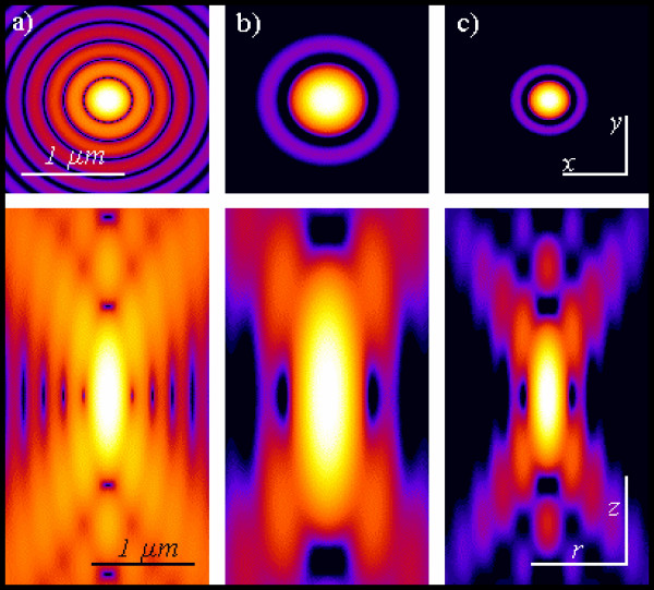
Pointlike emitter optical response. From left to right: calculated x-y (above) and r-z (below) intensity distributions, in logarithmic scale, for a point like source imaged by means of wide-field, 2PE and confocal microscopy. Both 2PE and confocal shapes exhibit a better signal to noise ratio than widefield case. 2PE distribution is larger due the fact that a wavelength twice than in the wide-field and confocal case is responsible for the intensity distribution. Such intensity distributions are also known as point spread functions of the related microscopes. Optical conditions: excitation wavelengths are 488 nm and 900 nm for 1PE and 2PE, respectively; emission wavelength is 520 nm; numerical aperture is 1.3 for an oil immersion objective with oil refractive index value set at 1.515.
where λ is the wavelength of light, η represents the refractive index of the imaging medium as described above, and the combined term η • sin(α) is known as the objective numerical aperture (NA). Objectives commonly used in microscopy have a numerical aperture that is less than 1.5, restricting the term α in Equations (2) and (3) to less than 70 degrees (although new high-performance objectives closely approach this limit). Therefore, the theoretical resolution limit at the shortest practical wavelength (approximately 400 nanometers) is around 150 nanometers in the lateral dimension and approaching 400 nanometers in the axial dimension when using an objective having a numerical aperture of 1.40. Thus, structures that lie closer than this distance cannot be resolved in the lateral plane using a microscope. Due to the central significance of the interrelationship between the refractive index of the imaging medium and the angular aperture of the objective, Abbe introduced the concept of numerical aperture during the course of explaining microscope resolution.
The main elements to realize a 2PE/MPE architecture, including confocal modality, are the following: high peak-power laser delivering moderate average power (fs or ps pulsed at relatively high repetition rate) emitting infrared or near infrared wavelengths (650–1100 nm), laser sources for confocal 1PE, a laser beam scanning system, high numerical aperture objectives (>1), a high-throughput microscope pathway, a spectral separation module for the emitted signal discrimination, and a high-sensitivity detection system [34]. Figure 8 shows a general scheme for a MPE microscope also illustrating two popular approaches that can be used for image formation, namely: de-scanned and non de-scanned mode. The former uses the very same optical pathway and mechanism employed in confocal laser scanning microscopy. The latter mainly optimises the optical pathway by minimising the number of optical elements encountered on the way from the sample to detectors, and increases the detector area. MPE non-descanned mode allows very good performances providing superior signal-to-noise ratio inside strongly scattering samples [32,33]. In the de-scanned approach pinholes are removed or set to their maximum aperture and the emission signal is captured using the very same optical scanning pathway used for excitation. In the latter, the aim is to optimize the collection efficiency: pinholes are removed and the radiation emitted without passing through the laser beam scanning mirrors. Photomultiplier tubes are the most popular detectors in MPE microscopy. Avalanche photodiodes are also excellent in terms of sensitivity exhibiting quantum efficiency close to 70%–80% in the visible spectral range. Unfortunately they are high cost and the small active photosensitive area could introduce drawbacks in the detection scheme and require special de-scanning optics. CCD cameras are generally used in video rate multifocal imaging. Laser sources represent the core element for the 2PE/MPE microscope since for MPE high photon flux densities are required, > 1024 photons cm-2s-1. Using radiation in the spectral range of 650–1100 nm for MPE, excitation intensities in the MW-GW cm-2 have to be produced. Nowadays, laser sources suitable for 2PE can be described as "turnkey" systems, and Ti Sapphire lasers are the most utilized due to the high coincidence with the 2PE wavelengths needed for the majority of the commonly used fluorescent molecules. Other laser sources used for 2PE are Cr-LiSAF, pulse-compressed Nd-YLF in the femtosecond regime, and mode-locked Nd-YAG and picosecond Ti-Sapphire lasers in picosecond regime. Moreover the absorption coefficients of most biological samples, cells and tissues are minimised within this spectral window. Table 2 reports data on the currently available laser sources for applications in MPE microscopy and spectroscopy. The parameters that are more relevant in the selection of the laser source are average power, pulsewidth and repetition rate, and wavelength also accordingly to equation (1). The most popular features for an infrared pulsed laser are 700mW-1W average power, 80–100 MHz repetition rate, and 100–150 fs pulse width. So far, the use of short pulses and high repetition rates are mandatory to allow image acquisition in a reasonable time while using power levels that are biologically tolerable. In order to minimise pulse width dispersion problems it should be considered to operate with pulses around 150 nm. This constitutes a very good compromise both for pulse stretching and sample viability. One should always remind that a shorter pulse broadens more than a longer one. Advances in laser sources are going on considering more compact sources, large tunability range, high average power, and special designs for tailored needs at lower prices [35]. Objective lenses influence the performances of any optical microscope, and for a MPE system special considerations have to be done taking into the proper account both equations (1) and (3). New technological requisites have to be considered with respect to conventional excitation fluorescence microscope. An adequate transmission in the IR regime has to be coupled with good collection efficiency towards the ultraviolet region. Moreover, the number of components should be minimised without affecting resolution properties in order to reduce pulse widths distortions. Although the collection efficiency of the time averaged photon flux is dependent on the numerical aperture of the collecting lens, the total fluorescence generation is independent of the numerical aperture of the focusing lens when imaging thick samples. Figure 9 shows an example of optical sectioning performed through a thick sample that exploits the autofluorescence signal. This is due to the fact that the increase of intensity, obtained by a sharper focusing (high NA), is counterbalanced by the shrinking of the excitation volume. Thus the total amount of fluorescence summed over the entire space remains constant. The very relevant practical consequence of this fact is that in 2PE measurements on thick samples, assuming no aberrations, the generated fluorescence is insensitive to the size of the focal spot. As a positive consequence, a moderate variation of the laser beam size would not affect the measurements. This is a very efficient condition due to the fact that using an appropriate (non-descanned) acquisition scheme it is possible to collect all the generated fluorescence. In terms of pulse broadening, a 100 fs pulse can result between 1.14 and 1.23 times at the sample using a good lens. Once a MPE architecture has been realized, one should consider to keep under control the following parameters: power and pulse width at the sample focal plane checking for the square intensity/power behaviour, spectral separation of the emitted fluorescence including removal of the possible excitation reflections that could be particularly subtle, z-axis precise control and laser-scanning system alignment [34]. Figure 10 and figure 11 demonstrate the multiple fluorescence imaging capability and 3D multiple fluorescence imaging, respectively.
In order to enable two objectives to be compared and to obtain a quantitative handle on resolution, the numerical aperture, or the measure of the solid angle covered by an objective is defined as:
Are you using the correct immersion oil? All objectives having a numerical aperture greater than 0.95 are designed for use with immersion media (usually oil of refractive index 1.515). Immersion oil is free of polychlorinated biphenyls and exhibits hardly any autofluorescence. The image will be markedly impaired if air bubbles are introduced into the immersion layer, so oil must be carefully applied to avoid bubbles. Air bubbles can be readily visualized by removing the eyepiece and examining the objective rear focal plane through the microscope observation tubes (or using a Bertrand lens). If air bubbles are observed, the objective and specimen slide should be cleaned and the oil carefully re-applied.
When light from the various points of a specimen passes through the objective and is reconstituted as an image, the various points of the specimen appear in the image as small patterns (not points) known as Airy patterns. This phenomenon is caused by diffraction or scattering of the light as it passes through the minute parts and spaces in the specimen and the circular rear aperture of the objective. The limit up to which two small objects are still seen as separate entities is used as a measure of the resolving power of a microscope. The distance where this limit is reached is known as the effective resolution of the microscope and is denoted as d0. The resolution is a value that can be derived theoretically given the optical parameters of the instrument and the average wavelength of illumination.
The most popular relationship about 2PE is related to the practical situation of a train of beam pulses focused through a high numerical aperture (NA) objective, with a duration τp and fprepetition rate. The advantage of using a train of repeated beam pulses is given by the fact that high peak power can be used for priming the process resulting on an average power tolerated by the biological system under investigation. Under controlled conditions, the probability, na, that a certain fluorophore simultaneously absorbs two photons during a single pulse, in the paraxial approximation is given by [20]
This is an Open Access article distributed under the terms of the Creative Commons Attribution License (http://creativecommons.org/licenses/by/2.0), which permits unrestricted use, distribution, and reproduction in any medium, provided the original work is properly cited.
Secure .gov websites use HTTPS A lock ( Lock Locked padlock icon ) or https:// means you've safely connected to the .gov website. Share sensitive information only on official, secure websites.


 Ms.Cici
 8618319014500