
How to create diffraction gratings from negative film - diffraction grating picture
Twolens magnificationcalculator
Placing a magnifier between the object and the eye permits the object to be moved closer to the eye, and the eye is able to focus on the virtual image formed, preferably, at the distance of most distinct vision. The regular magnification, M, is the ratio of the angle θ' subtended by the image to the angle θ subtended by the object.
Dyes, stains, or fluorescent proteins that label components of a specimen are known as fluorescence indicators or fluorophores. These fluorophores are the molecules that absorb and emit light at specific wavelengths to produce a fluorescent image. When multiple probes are required, careful selection of fluorophores with non-overlapping Stokes shift wavelengths are desired to minimize ‘bleed-through’ between signals.9
This post provides just a few glimpses into the vast repertoire of possibilities offered by fluorescence microscopy. To elaborate the variants of this rapidly growing field is beyond the scope of this article. But an important take-home point is the necessity of high-quality fluorophores suitable for both live and fixed specimen imaging. Biotium offers the widest range of reagents needed for all arenas of fluorescent imaging. Through cutting-edge research and development, Biotium is dedicated to developing high-performance tools for fluorescence-based biological research.
Magnificationformula forlensin termsoffocal length
If you know the distance of the object you're magnifying from the lens and the focal length of the lens, finding the distance of the image is easy with the lens equation.
E-Tay magnifier factory is a professional manufacturer to offer superior quality magnifying glass products,and provide perfact service for our clients.
Discover precision-crafted magnifying solutions with E-Tay's extensive range of optical magnifiers. Since 1980, our FDA-recognized and CE/RoHS-compliant magnifiers, including innovative lighted and hands-free models, have empowered businesses with unparalleled clarity and quality. Partner with E-Tay for magnifying excellence.
A magnifier is any positive lens with a focal length of less than 250 mm. The approximate magnification M provided by the lens is calculated by dividing its focal length into 250.
Magnificationformula Biology
In the 1670s, Dutch scientist Antonie Von Leeuwenhoek first discovered microbial life forms through his simple light microscope, a finding that would initiate a revolution in the field of microscopy.1 Since his early observations of what he termed ‘animacules’, the field has seen a quantum leap from his self-designed single lens microscopes to the current high resolution cryo-electron microscopes.2 Among these technological advances was the advent of fluorescence microscopy, a field that remains pivotal to modern biological research.3 In this article we will explore the basic principles governing fluorescence microscopes, the components involved, and its different variants.
Magnificationformula in Physics
Gopal Ramakrishnan holds a PhD in Biochemistry from the All India Institute of Medical Sciences. Dr. Ramakrishnan received his Post-Doctoral training at the Cancer Institute, University of Mississippi Medical Centre where he studied cell signaling, metabolism, development and cancer biology. He currently serves as a Research Assistant Professor at the University of Illinois in Chicago.
An aspheric lens is an ideal magnifier from several points of view. When used at its conjugates, there is no distortion of the image (a rectangular grid remains a rectangular grid after magnification). If the lens is large enough for the object to be viewed with both eyes, the view is stereosopic. To calculate magnification, use the following formula: M (magnification) = the height of the image ÷ by the height of the object. Plug your data into the formula and solve. If your answer is greater than 1, that means the image is magnified. If your answer is between 0 and 1, the image is smaller than the object.
A lens's focal length is the distance from the center of the lens to the point where the rays of light converge in a focal point. If you've ever focused light through a magnifying glass to burn ants, you've seen this. In academic problems, this is often given to you. In real life, you can sometimes find this information labeled on the lens itself.
How to calculate magnification of adrawing
Photobleaching occurs when fluorophores are photochemically altered by the excitation source such that the molecule is unable to fluoresce. This is particularly pertinent to laser scanning confocal microscopes due to the high energy from excitation lasers. This also affects the level of tissue penetration for 3D imaging, before photobleaching occurs. Two-photon microscopy addressed this issue by “splitting” a single photon into two photons with half the energy. This allowed comparable excitation while achieving significant reduction in photobleaching as well as enhanced resolution. This hypothesis was formulated by Maria Gopport- Mayer and was put to practical use by Winfried Denk in the 1990s by construction of the first two-photon excitation (2PE) laser confocal microscope.11
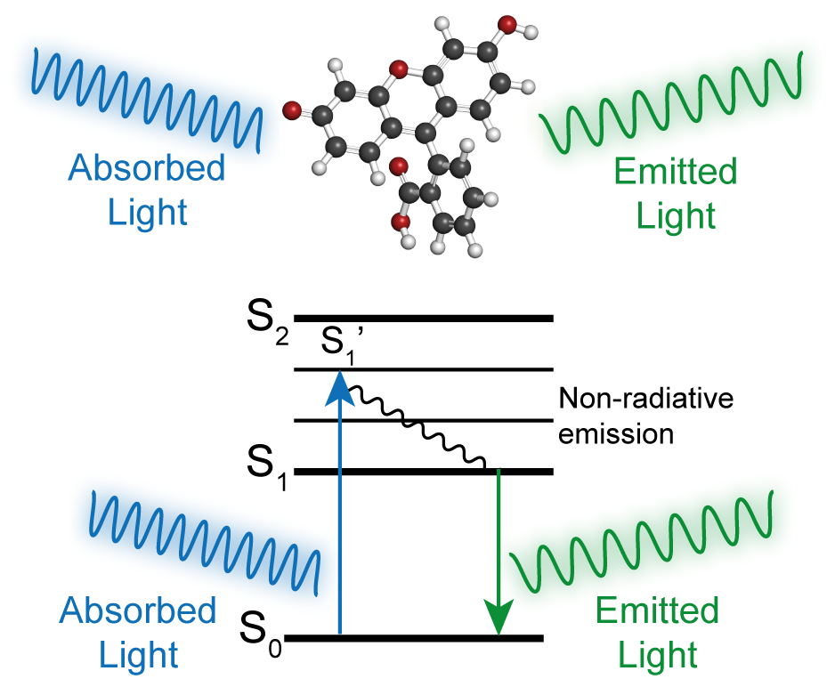
Biological specimens pose a unique challenge to imaging due to their low refractive indexes comparable to water, resulting in light scattering and reduced contrast. Staining and fluorescence technologies were discovered, chiefly to tackle this issue. The term ‘fluorescence’ was coined by physicist George Gabriel Stokes to describe the difference in a molecule’s emission and excitation wavelengths.4 Light is a form of electromagnetic radiation that has inherent energy in the form of photons.5 Fluorescence occurs when a molecule absorbs photons from an excitation source which “bumps up” the electrons to an unstable higher energy level. Eventually the “excited” electrons fall back to their stable lower energy levels. But in doing so they lose some of the excess energy absorbed by emitting the emission of photons, a process that occurs within a few nanoseconds. Because of this energy loss, the emitted photon has less energy than the absorbed photon (Fig 1.). In other words, the emitted photon is of a higher wavelength than the excited photon. This change in energy is called a Stokes shift.6
So far we have learned how to find the irradiance and power entering a lens and at a spot on a screen and also the minimum irradiance needed to burn a hole in the screen, yet we have not really discussed much about the spot's size that is viewed on the screen. Looking at the data for the three magnifying lenses and the reading glasses we see that the size of the spots change for each lens. What do these different spot sizes represent, do they effect the irradiance or anything we have observed so far and given a specific lens can we actually predict the spot size we will see? By utilizing (1) we can find the magnification of a lens by:
The basic fluorescent microscope carries a laser that provides the excitation light which is filtered by custom excitation filters. Similarly, emission filters are placed in the path of the emitted light beam from the sample, blocking out all undesired wavelengths, thereby ensuring a high signal-to-noise ratio (Fig. 2).7,8 Epi-illumination is a form of reflective optics, where the excitation and emission light beam are on the same side of the specimen. This enables the capture of weak emission signals from the specimen and greatly reduces noise from the transmitted light beam. With the invention of dichroic mirrors in the 1960s, this became the template for all epi-fluorescent microscope designs. In standard fluorescent microscopes, the dichroic mirror serves as the primary optical element separating the excitation and emission light. The mirror is placed at a 45⁰ angle and reflects the shorter excitation wavelength toward the specimen while the longer emitted wavelength is transmitted by the dichroic mirror for observation.
Magnificationformula for mirror
E-Tay continuously to designing innovative magnifiers, both with advanced technology and 38 years of experience, E-Tay ensures that each customer's demands are met.
E-Tay How do I calculate magnification for my magnifier? Introduction. An aspheric lens is an ideal magnifier from several points of view. When used at its conjugates, there is no distortion of the image (a rectangular grid remains a rectangular grid after magnification). If the lens is large enough for the object to be viewed with both eyes, the view is stereosopic.To calculate magnification, use the following formula: M (magnification) = the height of the image ÷ by the height of the object. Plug your data into the formula and solve. If your answer is greater than 1, that means the image is magnified. If your answer is between 0 and 1, the image is smaller than the object. E-Tay magnifier factory is a professional manufacturer to offer superior quality magnifying glass products,and provide perfact service for our clients.. E-Tay is one of the largest and most respected manufacturers of optical magnifiers for a wide variety of applications and magnifying glass, fresnel CPV solar magnifier lens Since 1980.
Magnificationformula for convexlens
It was not until the early 1900s that the principles of fluorescence was extrapolated to microscopy. The first working fluorescent microscope was developed by Oskar Heimstaedt in 1911. Initially, fluorescence microscopy was performed with transmitted light, with the path of the light beam following the design of a light microscope. The problem with this layout was that the emitted fluorescence is weak in comparison to the excitation light, resulting in masking the signals from the specimen. This issue was rectified by Philip Ellinger and August Hert in 1929 by placing the excitation and emission optics on the same side of the specimen, a method known as epi-illumination.1,4,6
Though confocal and two-photon microscopy vastly improved the issues of resolution and photobleaching, they still proved inadequate for the purpose of single-molecule resolution and imaging. TIRF exploits the principle of reflection in such a way that the excitation beam is aimed at the critical angle that causes total internal reflection on the surface of the cover-glass. This assists in achieving enhanced resolution close to the surface of the cover-glass to a depth of 100 nm or less, thereby matching atomic scale resolution. The advantages of TIRF was successfully demonstrated with single ATP turn-over reaction in single myosin molecules in 1995.8
Lensformula
Located in Taiwan since 1980, E-TAY INDUSTRIAL CO., LTD. is a magnifying glass products manufacturer. It's wide range of magnifying glasses include, magnifying glass with light, eclipse glasses, kids magnifying glasses, dome magnifiers, reading magnifiers, hand free magnifiers, hand held magnifiers, headband magnifiers, which are FDA approved and CE/RoHS compliant in the optical industry.

The basic fluorescence microscope offers a wide-field view with respect to specimen imaging. This broad illumination field lead to noise from regions outside the plane of focus (bidirectionally as in horizontal and vertical planes), leading to lower resolution. A simple solution for this was placing a pinhole between the path of both the excitation and emission light beams, a technology now known as confocal microscopy. Apart from superior resolution, confocal technology also facilitated the scanning of a specimen to reconstruct complex high-resolution three-dimensional images.10
true for a virtual image at infinity. Fresnel lenses are generally used to magnify objects slightly. One usually expects to see the entire object at once within the Fresnel lens, so that the lens must then be 1.2 or 1.5 times the size of the object in both length and width. That's why the equation is +1. According to the thin lens equation, our postcard sized magnifier with a focal length of 80mm will then have a power of 4x.


 Ms.Cici
 8618319014500