
How To Calculate Total Magnification Of A Microscope Or ... - how to compute magnification
Dispersioninopticalfiber
F2 is a flint glass that offers excellent performance in the visible and NIR spectral range. It offers a high refractive index and low Abbe number, making it excellent for use in an equilateral dispersive prism. Compared to N-SF11, it offers superior chemical resistance and slightly higher transmission.
Dispersive prisms are typically used at the minimum angle of deviation. This is the angle for which the wavelength of interest will travel parallel to the base of the prism, and the angle of incidence is equal to the angle of refraction when measured with respect to the normal of the prism face at the respective interface (see the Equilateral Tutorial tab for more information). At the minimum angle of deviation, a maximum clear aperture is achieved and reflective loss of p-polarized light is reduced since the angle of incidence is nearly Brewster's angle. For s-polarization, a custom antireflective coating can be used to minimize surface reflections.
Zine Selenide Zinc Selenide is ideal for use in the 600 nm to 16 µm wavelength range. It features low absorption (including in the red visible wavelength range) and high resistance to thermal shock. ZnSe is ideal for use in CO2 laser systems operating at 10.6 µm, including those with HeNe alignment lasers. Please note that, due to its low hardness, care should be taken when handling ZnSe optics.
Chromaticdispersion optical
Calcium FluorideCaF2 is commonly used for applications requiring high transmission in the infrared and ultraviolet spectral ranges. The material exhibits a low refractive index, varying from 1.35 to 1.51 within its usage range of 180 nm to 8.0 µm, as well as an extremely high laser damage threshold. Calcium fluoride is also fairly chemically inert and offers superior hardness compared to its barium fluoride, magnesium fluoride, and lithium fluoride cousins.
Waveguide dispersion can be reduced using fibers with larger cores, which allow more propagation modes and reduce the difference in the effective refractive index between the modes.
N-SF11, F2, and N-F2Both N-SF11 and F2 offer excellent performance in the visible range. When compared to each other, F2, which is a flint glass, has superior chemical resistance and better transmission than N-SF11. For instance, at 420 nm the theoretical internal transmittance of a 10 mm thick piece of F2 is 0.995, whereas for the same thickness of N-SF11, the internal transmittance is 0.910. If the glass is increased to a thickness of 25 mm, these internal transmission values decrease to 0.987 and 0.790, respectively. With high indices of refraction and low Abbe Numbers Vd, N-SF11 and F2 provide maximum dispersive power.
Dispersion opticalwavelength
An optical signal can have different wavelengths that travels at a slightly different speed and arrive at the receiver at different times within the mode causing the signal to spread out and become distorted. This type of dispersion is called Intramodal dispersion and occurs in both single and multimode fibers.
Intramodal dispersion can be further divided into material dispersion and waveguide dispersion. The delay difference due to the waveguide materials' dispersive properties is termed as material dispersion, and due to the geometry of the waveguide leads to waveguide dispersion.
s-pol. and p-pol. are displaced by 2.7 or 4.0 mm. Beam displacing prisms can be used as polarizing beamsplitters where 90o separation is not possible.
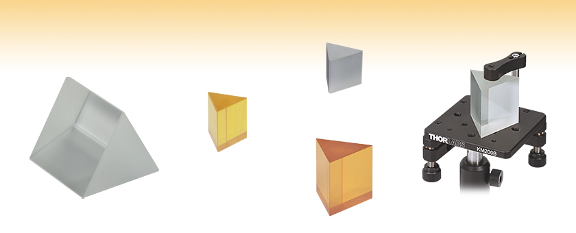
Please refer to the Prism Guide tab above for assistance in selecting the appropriate prism for your application, or to view Thorlabs' extensive line of prisms, please click here.
Single prism configuration and birefringent calcite separate an input beam into two orthogonally polarized output beams.
This equation can be used for prisms with n < 2.0; if the refractive index is higher, this geometry will cause total internal reflection at angle C above. ZnSe dispersive prisms, like the PS860 and PS861 prisms sold below, will have a beam exiting from the bottom face of the prism.
At the design wavelength (633 nm), the indices of refraction for N-SF11 and F2 are 1.779 and 1.617, respectively. Solving for γ in the equation above yields 65.6o for N-SF11 and 47.9o for F2.
Dispersion opticalpdf
Note: Transmission data is for two 25 mm right-angle prisms contacted into a cube. Click here to download substrate transmission data.
Now, consider the triangle outlined in green in the figure below. Here, (90 - θ1) + (90 - θ2) + 60o = 180o. Thus, θ1 + θ2 = 60o. Substituting this relationship into the end result derived in the previous paragraph, yields γ = + β - (θ1 + θ2) = + β - 60o.
N-F2 is a RoHS compliant material that has been engineered to have nearly identical optical properties as F2. Like F2, it is a flint glass that offers excellent performance in the visible and NIR spectral range. It offers a high refractive index and low Abbe number, making it excellent for use in an equilateral dispersive prism.
Note: Transmission data is for two 25 mm right-angle prisms contacted into a cube. Click here to download substrate transmission data.
Waveguidedispersion
If one were to use ray tracing techniques to determine the light propagation path due to the presence of the equilateral prism shown to the right, you would find that for most incidence angles, the angle of deviation of the transmitted ray (denoted by γ in the figure to the right) is roughly the same, regardless of the angle of incidence considered. However, although the angle of deviation is largely unchanged, there is a minimum value that is obtainable. This angle is known as the minimum angle of deviation; it occurs when the light ray passing through the prism is parallel to the prism's base (as shown to the right), and therefore, = β (i.e., the angle of the light ray entering the prism is identical to that of the light ray exiting the prism).
Waveguide dispersion, however, may be significant in single-mode fibers where the effects of the various dispersion mechanisms are difficult to distinguish.
The amount of pulse broadening depends on several factors, including the length of the fiber, the wavelength of the light, and the properties of the fiber itself, such as its refractive index profile and material composition. Pulse broadening can limit the maximum data rate that can be transmitted over long distances in optical communication systems.
Waveguide dispersion is always negative in optical fibers due to the difference in effective refractive index for different modes of light, which is a result of the fiber's geometry and the way the refractive index of the fiber changes with frequency. The higher-order modes experience a lower effective refractive index than the lower-order modes.
s-pol. and p-pol. deviate symmetrically from the prism. Wollaston prisms are used in spectrometers and polarization analyzers.
N-SF11 is a flint glass that offers excellent performance in the visible and NIR spectral range. It offers a high refractive index and low Abbe number, making it excellent for use in an equilateral dispersive prism.
Double prism configuration and birefringent calcite produce a polarizer with the widest field of view while maintaining a high extinction ratio.
When both wedges are rotated, the beam can be moved anywhere within the circle defined by 4 times the specified deviation angle.
Dispersionin Physics
Dispersion opticalformula
An optical signal is an electromagnetic signal that consists of different wavelengths. Each wavelength components travels through the fiber at different speeds depending on the refractive index of the material. These individual wavelengths reach the other end of the fiber at different time. It can cause the wave to spread out and become distorted over time. This broadening of pulses over time is called Dispersion. The distortion of optical signals affects the quality of the signals. It may be observed that each individual pulse within the signal broadens and overlaps with its neighbours, eventually becoming indistinguishable at the receiver input.
Some of these light rays will travel in a straight path through the center of the fiber called the axial mode. The remaining light rays will repeatedly bounce off the core-cladding boundary as they travel through the waveguide. Each mode propagating within the fiber follows a different angle and paths. As these modes travel at different speeds, it reaches the fiber output at different time. The differences in the propagation time for each of these modes results in the spreading out of signals between the modes. This is called inter-modal dispersion. The spreading out causes signal overlapping which makes it difficult to distinguish them separately. As the path length increases, there will be a corresponding increase in the dispersion of the modes. The pulse width at the output depends on the transmission times of the slowest and fastest modes.
In materials with normal dispersion, the refractive index decreases as the wavelength of light increases. This means that the longer wavelengths of light (such as red) travel faster than the shorter wavelengths (such as blue), causing the pulse to spread out over time. In this case, the sign of dispersion is negative.
Thorlabs offers a wide variety of prisms, which can be used to reflect, invert, rotate, disperse, steer, and collimate light. For prisms and substrates not listed below, please contact Tech Support.
Materialdispersion
Thorlabs will accept all ZnSe prisms back for proper disposal. Please contact Tech Support to make arrangements for this service.

To illustrate the relationship between the incident, exit, and deviation angles in the triangle to the right, consider the equilateral triangle shown below, which is identical to the one shown to the right but has several more angles labeled. Using the geometric relationships that exist for vertical angles, it becomes apparent that A = - θ1 and C = β - θ2. Since the angles A, B, and C define a triangle, we know that A + B + C = 180o, and thus, B = 180o - (A + C) = 180o - [( - θ1) + (β - θ2)]. Finally, B + γ = 180o, so γ = 180o - B = [( - θ1) + (β - θ2)].
Waveguide dispersion, on the other hand, is caused by the geometry of the fiber optic cable itself. This type of dispersion occurs because the light waves that propagate through the fiber are confined to a narrow waveguide structure, which can cause the different wavelengths of light to travel at different speeds due to the geometrical variations. It can cause the signal to spread out and become distorted, and is typically more prominent at shorter wavelengths. Waveguide dispersion can be reduced by using fibers with a wider core diameter or by using specialized waveguide structures to improve the uniformity of the waveguide geometry. It occurs in both single and multi-mode optical fiber.
For the angle of minimum deviation, = β, so there is a simple relationship between the angle of incidence and the angle of minimum deviation:
The dispersion can also have useful applications such as fiber optic sensors, dispersion compensation systems, optical sensing, nonlinear optics, pulse shaping, wavelength division multiplexing, biomedical applications such as optical coherence tomography (OCT), gemology, imaging, and pulsar emissions.
Zinc Selenide is ideal for use in the 600 nm to 16 µm range. It features low absorption (including in the red visible wavelength range) and high resistance to thermal shock. ZnSe is ideal for use in CO2 laser systems operating at 10.6 µm, including those with HeNe alignment lasers. Note that due to their high refractive index, these prisms can not be used in the traditional orienation described in the Equilateral Tutorial tab above.
It can also be used to design integrated optical circuits, devices that manipulate light at a small scale. Dispersion is also used to analyze the frequency response of waveguide structures, such as filters and resonators.
Light has two different polarization modes that travel at different speed inside the core due to the variations in refractive index. This phenomenon is called birefringence, where the refractive index of the fiber is different for light polarized in different directions. This arise due to the asymmetry of the fiber structure. The difference in speed results in the delay in arrival of signal and the pulse broadening. This kind of dispersion due to the light distributed over different polarizations is polarization mode dispersion.
The index of refraction of various materials can be calculated via the Sellmeier equation. Each material is empirically assigned a set of coefficients, through which the index of refraction can be calculated at any wavelengtha.
On the other hand, in materials with anomalous dispersion, the refractive index increases as the wavelength of light increases. This means that the shorter wavelengths of light (such as blue) travel faster than the longer wavelengths (such as red), causing the pulse to also spread out over time. In this case, the sign of dispersion is positive.
Polarization EffectsFor p-polarized light (blue line) incident on a dispersing prism at the angle of least deviation, the graph to the right shows that only a small percentage of the p-polarized light is reflected at the surface. Thus, for this polarization, the transmission through a prism fabricated from F2 will be excellent even though there is no AR coating on the surface.
When handling optics, one should always wear gloves. This is especially true when working with zinc selenide, as it is a hazardous material. For your safety, please follow all proper precautions, including wearing gloves when handling these prisms and thoroughly washing your hands afterward. Due to the low hardness of ZnSe, additional care should be taken to not damage these prisms. Click here to download a pdf of the MSDS for ZnSe.

Our Dispersive Equilateral Prisms, which are fabricated from F2, N-F2, N-SF11, CaF2, or ZnSe are available in sizes ranging from 10 mm to 50 mm. These prisms create less stray light than diffraction gratings, thereby eliminating the higher order problems typically associated with gratings.
Polarization EffectsFor p-polarized light (blue line) incident on a dispersing prism at the angle of least deviation, the graph to the right shows that only a small percentage of the p-polarized light is reflected at the surface. Thus, for this polarization, the transmission through a prism fabricated from N-F2 will be excellent even though there is no AR coating on the surface.
Intramodal dispersion is expressed in terms of the chromatic dispersion parameter D, which is related to β, the mode propagation constant, a function of size of the fiber’s core relative to the wavelength of operation.
In optical fibers, modes refer to the different paths that light can take as it travels through the fiber core. The fiber can be classified into two types based on the number of propagation modes they support: single-mode (only one propagation mode) and multimode fibers (simultaneous propagation of multiple distinct light modes).
CaF2 is commonly used for applications requiring high transmission in the infrared and ultraviolet spectral ranges. The material exhibits a low refractive index, varying from 1.35 to 1.51 within its usage range of 180 nm to 8.0 µm, as well as an extremely high laser damage threshold. Calcium fluoride is also fairly chemically inert and offers superior hardness compared to its barium fluoride, magnesium fluoride, and lithium fluoride cousins.
By applying Snell's Law to the interfaces of prism and using a little calculus, a general equation for the relationship between the index of refraction of the equilateral prism n and the angle of minimum deviation γ can be obtained:
By rotating one wedged prism, light can be steered to trace the circle defined by 2 times the specified deviation angle.
Both material and waveguide dispersion are measured in picoseconds per nanometer per kilometer. This cause an increase in magnitude of source linewidth and an increase in dispersion with fiber length.
In an optical fiber, light propagates through the core of the fiber, which is surrounded by a cladding layer with a lower refractive index. Light at shorter wavelengths stays more in the core, while longer wavelengths is distributed in the cladding. The longer wavelengths travels at a higher propagation speed than the shorter wavelengths due to the lower refractive index of the cladding. This time delay results in the spreading out of the signals.
Material dispersion is caused by the variation in the refractive index of the material used in the optical fiber. Since the refractive index of the material determines the speed at which light propagates through the fiber, different wavelengths of light travel at different speeds, causing the signal to spread out and become distorted. The sign of material dispersion can be positive or negative depending on the material properties and the wavelength of the transmitted light. The sign of dispersion refers to the direction of the change in refractive index with respect to the change in wavelength.
Polarization EffectsFor p-polarized light (blue line) incident on a dispersing prism at the angle of least deviation, the graph to the right shows that only a small percentage of the p-polarized light is reflected at the surface. Thus, for this polarization, the transmission through a prism fabricated from N-SF11, a RoHS-compliant version of SF11, will be excellent even though there is no AR coating on the surface.
N-F2 is a RoHS compliant material that has been engineered to have nearly identical optical properties as F2. At 633 nm, both N-F2 and F2 have an index of refraction of 1.617, and they have nearly identical Abbe numbers of 36.43 and 36.37, respectively.


 Ms.Cici
 8618319014500