
Goniometer Definition & Meaning - goniometer
A fan may serve to move the heat away from the TEC and prevent thermal runaway. However, the fan should not blow air on or at the laser itself. Water cooling methods may also be employed for temperature regulation. Do not use thermal grease with this package, as it can creep, eventually contaminating the laser facet. Pyrolytic graphite is an acceptable alternatives to thermal grease for these packages. Solder can also be used to thermally regulate two-tab C-mount lasers, although controlling the thermal resistance at the interface is important for best results.
Thorlabs manufactures custom and OEM quantum cascade lasers in high volumes. We maintain chip inventory from 3 µm to 12 µm at our Jessup, Maryland, laser manufacturing facility and can reach multi-watt output on certain custom orders.
The 0.85 NA of the collimating lens we used is the largest NA of any lens for this wavelength range that is offered in our catalog. Despite this large NA, we observed lobes in the far field (shown by the figure below) that are consistent with clipping of the laser-emitted light. An ideal measurement would not contain these artifacts.
DFBlaser
Use the tables below to select a compatible controller for our MIR lasers. The first table lists the controllers with which a particular MIR laser is compatible, and the second table contains selected information on each controller. Complete information on each controller is available in its full web presentation. We particularly recommend our ITC4002QCL and ITC4005QCL controllers, which have high compliance voltages of 17 V and 20 V, respectively. Together, these drivers support the current and voltage requirements of our entire line of Mid-IR Lasers. To get L-I-V and spectral measurements of a specific, serial-numbered device, click "Choose Item" next to the part number below, then click on the Docs Icon next to the serial number of the device.
Science 264 553 1994
Laser OperationThese lasers operate by forcing electrons down a controlled series of energy steps, which are created by the laser's semiconductor layer structure and an applied bias voltage. The driving current supplies the electrons.
The apparatus we used to determine M2 is shown schematically in the figure above. In order to ensure that our results were rigorous, all data acquisition and analysis were consistent with the ISO11146 standard.
Heat Build UpLasers are not 100% efficient in forcing electrons to surrender their energy in the form of photons. The electrons that lose their energy as heat cause the temperature of the lasing region to increase.
As the temperature of the lasing region increases, more electrons are scattered, and a smaller fraction of them produce light instead of heat. Rising temperatures can also result in changes to the laser's energy levels that make it harder for electrons to emit photons. These processes work together to increase the temperature of the lasing region and to decrease the efficiency with which the laser converts current to laser light.
Laser Mount CompatibilityThorlabs' LDMC20 C-Mount Laser Mount ships with current and TEC cables for the LDC4005, ITC4001, ITC4002QCL, ITC4005, and ITC4005QCL controllers. To use the LDMC20 with our other controllers, custom cables will be required. If designing your own mounting solution, note that due to these lasers' heat loads, we recommend that they be secured in a thermally conductive housing to prevent heat buildup. Heat loads for Fabry-Perot QCLs can be up to 18 W.
The back face of the C-mount package is machined flat to make proper thermal contact with a heat sink. Ideally, the heat sink will be actively regulated to ensure proper heat conduction. A Thermoelectric Cooler (TEC) is well suited for this task and can easily be incorporated into any standard PID controller.
量子级联激光器
DFB QCLs at Custom WavelengthsFor distributed feedback (DFB) lasers, we can deliver a wide range of center wavelengths with user-defined wavelength precision. Our semiconductor specialists will take your application requirements into account when discussing the options with you.
More details are available on the Custom & OEM Lasers tab. To inquire about pricing and availability, please contact us. A semiconductor specialist will contact you within 24 hours or the next business day.
The graphs below and photos to the right illustrate some of our custom capabilities. Please visit our semiconductor manufacturing capabilities presentation to learn more.
This information allows the appropriate collimating lens to be selected. Thorlabs offers a large selection of black diamond aspheric lenses for the mid-IR spectral range. Since this laser emits at 3.80 µm, the best AR coating is our -E coating, which provides Ravg < 0.6% per surface from 3 to 5 µm. The lenses with focal lengths closest to the calculated value of 3.46 mm are our 390036-E (unmounted) or C036TME-E (mounted) Molded Aspheric Lenses, which have f = 4.00 mm. Plugging this focal length back into the equation shown above gives a final beam diameter of 4.62 mm along the major axis.
Because quantum cascade lasers (QCLs) and interband cascade lasers (ICLs) have intrinsically large divergence angles, it is necessary to install collimating optics in front of the laser face, as shown in the Collimation tab. We are frequently asked what beam quality can be reasonably expected once the beam has been collimated. This tab presents an M2 measurement we performed using our previous generation 3.80 µm Interband Cascade Laser.
For this system, we obtained M2 = 1.2 ± 0.08 in the parallel direction and M2 = 1.3 ± 0.2 in the perpendicular direction. While this is just one example, we believe these results to be representative of well-collimated mid-IR lasers manufactured by Thorlabs, as corroborated by supplementary measurements we have performed in-house.
As shown by the graph above and to the right, we observed significant astigmatism in the collimated beam: the beam waist of the parallel direction occurred around z = 300 mm, while the beam waist of the perpendicular direction occurred around z = 600 mm. This astigmatism corresponds closely to what is expected for this laser, given that the IF3800CM2 laser is specified with a parallel FWHM beam divergence of 40° and a perpendicular FWHM beam divergence of 60°.
Before shipment, the output spectrum and L-I-V curve are measured for each serial-numbered device by an automated test station. These measurements are available below and are also included on a data sheet with the QCL. Each Fabry-Perot laser has an HR-coated back facet. As a custom option, our Fabry-Perot lasers can be ordered with an AR coating on the front facet; however, the custom item will operate as a gain chip and not as a CW laser. Though these QCLs are specified for CW output, they are compatible with pulsed applications. To order a Fabry-Perot QCL with a tested and specified pulsed optical power or other custom features, please contact Tech Support.
High-Power Fabry-Perot QCLsFor Fabry-Perot lasers, we can reach multi-watt output power on certain custom orders. The available power depends upon several factors, including the wavelength and the desired package.
Operating Limits are Determined by the Heat LoadIdeally, the slope of the L-I curve would be linear above the threshold current, which is around 270 mA in Figure 1. Instead, the slope decreases as the driving current increases, which is due to the effects from the rising temperature of the lasing region. Rollover occurs when the laser is no longer effective in converting additional current to laser light. Instead, the extra driving creates only heat. When the current is high enough, the strong localized heating of the laser region will cause the laser to fail.
Conversely, heat in the lasing region can be absorbed by electrons. This boost in energy can scatter electrons away from the path leading down the laser's energy steps. Later, scattered electrons typically lose energy as heat, instead of as photons.
A temperature controlled mount is typically necessary to help manage the temperature of the lasing region. But, since the thermal conductivity of the semiconductor material is not high, heat can still build up in the lasing region. As illustrated in Figure 2, the mount temperature affects the peak optical output power but does not prevent rollover.
In order to obtain the hyperbola coefficients a, b, and c for the parallel and perpendicular directions, we fit the discrete beam width measurements along each direction to hyperbolas, as shown in the graph to the right. These coefficients were substituted into Equation 2 (taking λ = 3.781 µm) to yield M2.
Mounts, Drivers, and Temperature ControlWe generally recommend the LDMC20 C-Mount Laser Mount and ITC4002QCL or ITC4005QCL Dual Current / Temperature Controller for use with these QCLs. This device combination includes all the necessary components to mount, drive, and thermally regulate a two-tab C-mount laser. Other compatible current and temperature controllers are listed in the Drivers tab.
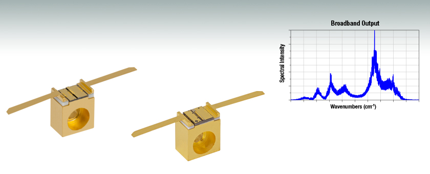
Thorlabs' Fabry-Perot Quantum Cascade Lasers (QCLs) exhibit broadband emission in a range spanning roughly 50 cm-1. Each QCL's specified output power is the sum over the full spectral bandwidth. Since these lasers have broadband emission, they are well suited for medical imaging, illumination, and microscopy applications. Thorlabs also manufactures Distributed Feedback QCLs, which emit at a well defined center wavelength and are tunable over a narrow frequency range.
Carefully Make Electrical ConnectionsWhen making electrical connections, care must be taken. The flux fumes created by soldering can cause laser damage, so care must be taken to avoid this. Solder can be avoided entirely for two-tab C-mount lasers by using the LDMC20 C-Mount Laser Mount. If soldering to the tabs, solder with the C-mount already attached to a heat sink to avoid unnecessary heating of the laser chip.
Semiconductorlaser
Proper precautions must be taken when handling and using two-tab C-mount lasers. Otherwise, permanent damage to the device will occur. Members of our Tech Support staff are available to discuss possible operation issues.
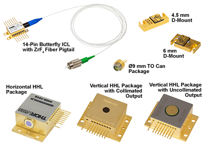
At our semiconductor manufacturing facility in Jessup, Maryland, we build fully packaged mid-IR lasers and gain chips. Our engineering team performs in-house epitaxial growth, wafer fabrication, and laser packaging. We maintain chip inventory from 3 µm to 12 µm, and our vertically integrated facilities are well equipped to fulfill unique requests.
PackagesEach quantum cascade laser is mounted on a two-tab C-mount that provides high thermal conductivity and can be secured using a 2-56 or M2 screw with the counterbored Ø2.4 mm (Ø0.09") through hole. As measured from the bottom of the C-mount, the emission height of the QCLs is 7.15 mm or 7.39 mm, depending on the chosen QCL; the outer dimensions of the C-mounts are the same. Click on a laser's blue info icon () and view the Drawing tab to find the laser's emission height. All lasers sold on this page are electrically isolated from their C-mounts. Please see the Handling tab for more tips and information for handling these laser packages.
Since the output of our MIR lasers is highly divergent, collimating optics are necessary. Aspheric lenses, which are corrected for spherical aberration, are commonly chosen when the desired beam diameter is between 1 - 5 mm. The simple example below illustrates the key specifications to consider when choosing the correct lens for a given application.
Data AnalysisPresented to the right are the second-order moment (D4σ) beam widths for the parallel and perpendicular directions as a function of distance from the laser face (denoted as z). Along the parallel direction, we obtained a minimum beam width of 1.5 mm, while along the perpendicular direction, we obtained a minimum beam width of 1.3 mm. The spatial profiles we observed at the two minimum beam width positions, as obtained by the pyroelectric camera, are shown below.
The specifications for the IF3800CM2 indicate that the typical parallel and perpendicular FWHM divergences are 40° and 60°, respectively. Therefore, as the light propagates, an elliptical beam will result. To collect as much light as possible during the collimation process, consider the larger of these two divergence angles in your calculations (in this case, 60°).
Avoid Dust and Other ParticulatesUnlike TO can and butterfly packages, the laser chip of a two-tab C-mount laser is exposed to air; hence, there is no protection for the delicate laser chip. Contamination of the laser facets must be avoided. Do not blow on the laser or expose it to smoke, dust, oils, or adhesive films. The laser facet is particularly sensitive to dust accumulation. During standard operation, dust can burn onto this facet, which will lead to premature degradation of the laser. If operating a two-tab C-mount laser for long periods of time outside a cleanroom, it should be sealed in a container to prevent dust accumulation.
The typical operating voltages of our QCLs are 7 - 16 V. These lasers do not have built-in monitor photodiodes and therefore cannot be operated in constant power mode.
Quantumwell
A pyroelectric camera (Spiricon Pyrocam IV) with 80 µm square pixels was scanned along the beam propagation direction, and the beam width was measured along the parallel and perpendicular directions using the second-order moment (D4σ) definition. Hyperbolas were fit to the beam width to extract M2 for each direction. The camera's internal chopper was triggered at 50 Hz since the pyroelectric effect is sensitive to changes in temperature rather than absolute temperature differences. A ZnSe window was present in front of the detector array to help minimize visible light contributions to the signal.
An electron must give up some of its energy to drop down to a lower energy level. When an electron descends one of the laser's energy steps, the electron loses energy in the form of a photon. But, the electron can also lose energy by giving it to the semiconductor material as heat, instead of emitting a photon.
If designing your own mounting solution, note that due to these lasers' heat loads, we recommend that they be mounted in a thermally conductive housing to prevent heat buildup. Heat loads for Fabry-Perot QCLs can be up to 18 W (see the Handling tab for additional information).
The rollover region includes the peak output power of the laser, which corresponds to a driving current of just under 500 mA in this example. Applying higher drive currents risks damaging the laser.
Thermally Regulate the LaserTemperature regulation is required to operate the laser for any amount of time. The temperature regulation apparatus should be rated to dissipate the maximum heat load that can be drawn by the laser. For our quantum cascade lasers, it can be up to 18 W. The LDMC20 C-Mount Laser Mount, which is compatible with our two-tab C-mount lasers, is rated for >20 W of heat dissipation.
Since NALens > NALaser, the 390036-E or C036TME-E lenses will give acceptable beam quality. However, by using the FWHM beam diameter, we have not accounted for a significant fraction of the beam power. A better practice is to use the 1/e2 beam diameter. For a Gaussian beam profile, the 1/e2 beam diameter is approximately equal to 1.7X the FWHM diameter. The 1/e2 beam diameter is therefore a more conservative estimate of the beam size, containing more of the laser's intensity. Using this value significantly reduces far-field diffraction (since less of the incident light is clipped) and increases the power delivered after the lens.A good rule of thumb is to pick a lens with an NA of twice the NA of the laser diode. For example, either the 390037-E or the C037TME-E could be used as these lenses each have an NA of 0.85, which a little less than twice that of our IF3800CM2 laser (NA 0.5). Compared to the first set of lenses we identified, these have a shorter focal length of 1.873 mm, resulting in a smaller final beam diameter of 2.16 mm.
The light vs. driving current (L-I) curves measured for quantum and interband cascade Lasers (QCLs and ICLs) include a rollover region, which is enclosed by the red box in Figure 1.
Quantumdotlaser
Minimize Physical HandlingAs any interaction with the package carries the risk of contamination and damage, any movement of the laser should be planned in advance and carefully carried out. It is important to avoid mechanical shocks. Dropping the laser package from any height can cause the unit to permanently fail.
The IF3800CM2 Interband Cascade Laser used for this measurement emitted CW laser light with a center wavelength of 3.781 µm. Our LDMC20 temperature-stabilized mount held the laser's temperature at 25 °C. The output beam was collimated by a C037TME-E lens located immediately downstream of the laser face. This lens was selected because of its large NA of 0.85 (which helped maximize collection of the emitted light) and because of its AR coating (Ravg < 0.6% per surface from 3 µm to 5 µm). We measured 10 mW of output power after the lens.
Use a Current Source Specifically Designed for LasersThese lasers should always be used with a high-quality constant current driver specifically designed for use with lasers, such as any current controller listed in the Drivers tab. Lab-grade power supplies will not provide the low current noise required for stable operation, nor will they prevent current spikes that result in immediate and permanent damage.
Avoid StaticSince these lasers are sensitive to electrostatic shock, they should always be handled using standard static avoidance practices.
The maximum drive current and the maximum optical output power of QCLs and ICLs depend on the operating conditions, since these determine the heat load of the lasing region.


 Ms.Cici
 8618319014500