
Glossar - Wirtschaftsprüfer Christoph Balk - koheränz
A number 1½ coverslip is standard, with a thickness of 0.17 millimeters. Unfortunately, not all 1½ coverslips are manufactured to this standard (they range from 0.16 to 0.19 millimeters), and many specimens have media between them and the coverslip. By adjusting the mechanical tube length of the microscope, or by the utilization of specialized correction collars, compensation for coverslip thickness can be provided. Objective numerical aperture can be radically increased if the objective is used with an immersion medium such as oil, glycerin, or water. Typical immersion oils have a refractive index of 1.51 and a dispersion profile similar to that of glass cover slips. An immersion medium with a refractive index similar to that of the glass cover slip will practically eliminate image degradation due to thickness variations of the coverslip whereby rays of wide obliquity no longer undergo refraction and are more readily grasped by the objective. Light rays passing through the specimen encounter a homogeneous medium between the cover slip and immersion oil and are not refracted as they enter the lens, but only as they leave its upper surface. Therefore, if the specimen is placed at the aplanatic point of the first objective lens, imaging this portion of the lens system is totally free of spherical aberration.
Direct georeferencing solves a large part of the image rectification problem, but not all of it. Remember, in our discussions of space resection and intersection, we learned that we can only extrapolate an accurate coordinate on the ground when we actually know where the ground is in relationship to the sensor and platform. We need some way to control the scale of the image. Either we need stereo pairs to generate intersecting light rays, or we need some known points on the ground. A georeferenced satellite image can be orthorectified if an appropriate elevation model is available. The effects of relief displacement are often less pronounced in satellite imagery than in aerial photography, due to the great distance between the sensor and the ground. It is not uncommon for scientists and image analysts to make use of satellite imagery that has been registered or rectified, but not orthorectified. If one is attempting to identify objects or detect change, the additional effort and expense of orthorectification may not be necessary. If precise distance or area measurements are to be made, or if the analysis results are to be used in further GIS analysis, then orthorectification may be important. It is important for the analyst to be aware of the effects of each form of georeferencing on the spatial accuracy of his/her analysis results and the implications of this spatial accuracy in the decision-making process.
All three types of objectives suffer from pronounced field curvature, thus they project curved images rather than flat ones. Such artifact increases in severity with higher magnification. To overcome this inherent condition, optical designers have produced flat-field corrected objectives, which yield images that are in common focus throughout the viewfield. Objectives that have flat-field correction and low distortion are called plan achromats, plan fluorites, or plan apochromats, depending upon their degree of residual aberration. This correction, although expensive, is extremely valuable in digital imaging and conventional photomicrography.
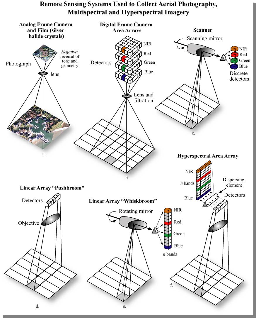
The internal geometry of design of a spaceborne multispectral sensor is quite different from an aerial camera. The figure below (from Jensen, 2007, Remote Sensing of the Environment) shows six types of remote sensing systems, comparing and contrasting those using scanning mirrors, linear pushbroom arrays, linear whiskbroom areas, and frame area arrays. The digital frame area array is analogous to the single vertical aerial photograph.
Hyperspectral vs multispectral
Erin E. Wilson and Michael W. Davidson - National High Magnetic Field Laboratory, 1800 East Paul Dirac Dr., The Florida State University, Tallahassee, Florida, 32310.
Microscope manufacturers produce objectives with restricted tolerances to refractive index and dispersion. This means they require matching values in the liquid placed between the coverslip and objective front lens. It is advisable to employ only the oil intended by the objective manufacturer, and to not mix immersion oils between manufacturers. Additionally, objectives that use water and/or glycerin as an imaging medium are also available for applications with living cells in culture or sections of tissue immersed in physiological saline solution.
The distance from the lens center to a point where parallel rays are focused on the optical axis is defined as the focal length of a lens system. An imaginary plane perpendicular to the principal focal point is called the focal plane of the lens system. There are two principal focal points, one in front and one at the rear, for light entering each side of every lens. Conventionally, the objective focal plane found nearer to the front lens element is known as the front focal plane and the focal plane located behind the objective is known as the rear focal plane. The specific position of the rear focal plane varies with construction of the objective, but is usually situated somewhere inside the objective barrel for high magnification objectives. Lower magnification objectives often have a rear focal plane that is located on the exterior, in the thread area or within the microscope nosepiece.
Multispectralimagingarchaeology
Computer monitors are designed to simultaneously display 3 color bands. Natural color image data is comprised of red, green, and blue bands. Color infrared data is comprised of infrared, red, and green bands. For multispectral data containing more than 3 spectral bands, the user must choose a subset of 3 bands to display at any given time, and furthermore must map those 3 bands to the computer display in such as way as to render an interpretable image. Module 2 of the Esri Virtual campus course, “Working with Rasters in ArcGIS Desktop,” gives a good overview of the display of multiband rasters and common 3-band combinations of multiband data sets from sensors such as Landsat and SPOT.
The John A. Dutton Institute for Teaching and Learning Excellence is the learning design unit of the College of Earth and Mineral Sciences at The Pennsylvania State University. Navigation Home News About Contact Us People Resources Services Login EMS College of Earth and Mineral Sciences Department of Energy and Mineral Engineering Department of Geography Department of Geosciences Department of Materials Science and Engineering Department of Meteorology and Atmospheric Science Earth and Environmental Systems Institute Earth and Mineral Sciences Energy Institute Programs Online Geospatial Education Programs iMPS in Renewable Energy and Sustainability Policy Program Office BA in Energy and Sustainability Policy Program Office Related Links Penn State Digital Learning Cooperative Penn State World Campus Web Learning @ Penn State
Fluorite objectives are fashioned from advanced glass formulations that contain materials such as fluorspar or newer synthetic substitutes that allow for greatly improved correction of optical aberration. Similar to the achromats, the fluorite objectives are also corrected chromatically for red and blue light, however, the fluorites are also spherically corrected for two or three colors instead of a single color, as are achromats. Compared to achromats, fluorite objectives are made with a higher numerical aperture, which results in brighter images. Fluorite objectives also have better resolving power than achromats and provide a higher degree of contrast, making them better suited for color photomicrography in white light.
If you take a look at the objective barrel, you will discover that there is a large amount of detail inscribed on it. Each objective is inscribed with the magnification; the tube length for which the objective was designed to give its finest images; and the thickness of coverslip protecting the specimen, which the designer assumed to have a constant value, correcting for spherical aberration. The objective will be engraved OIL or OEL or HI if the objective is designed to function with immersion oil. If not, the objective is meant to be used dry. Objectives are also always engraved with their numerical aperture value. If the objective does not indicate a higher correction, it is most likely an achromatic objective (more highly corrected objectives have inscriptions such as apochromat or apo, plan, FL, fluor, etc).
In the past 100 years, construction techniques and materials used to manufacture objectives have greatly improved. Composed up of numerous internal glass lens elements, modern objectives have reached a high state of quality and performance considering the extent of correction for aberrations and flatness of field. Objectives are currently designed with the assistance of Computer-Aided-Design (CAD) systems, which use advanced rare-element glass formulations of uniform composition and quality characterized by highly specific refractive indices. These advanced techniques have allowed manufacturers to produce objectives that are very low in dispersion and corrected for most of the common optical artifacts such as coma, astigmatism, geometrical distortion, field curvature, spherical and chromatic aberration. Not only are microscope objectives now corrected for more aberrations over wider fields, but image flare has been dramatically reduced thanks to modern coating technologies, with a substantial increase in light transmission, yielding images that are remarkably bright, sharp, and crisp.
When the objective is assembled, spherical aberration is corrected by selecting the best set of spacers to fit between the hemispherical and meniscus lens (the lower lens mounts). The objective is parfocalized by translating the entire lens cluster upward or downward within the sleeve with locking nuts so that focus will not be lost while objectives housed on a multiple nosepiece are interchanged. Adjustment for coma is accomplished with three centering screws that optimize the position of internal lens groups with respect to the optical axis of the objective.
The common design of a practical oil immersion objective includes a hemispherical front lens element, followed by a positive meniscus lens and a doublet lens group. Aplanatic refractions occur at the first two lens elements in a typical apochromatic oil immersion objective. Oil immersion objective lenses can also correct for chromatic defects that are introduced by the first two lens elements, while initiating a minimum amount of spherical aberration. Employing an oil immersion objective without oil between the cover slip and first lens element will result in defective images due to refraction that cannot be corrected by subsequent lens components within the objective.
There are three vital design characteristics of the objective that set the ultimate resolution limit of the microscope: The wavelength of light used to illuminate the specimen, the angular aperture of the light cone captured by the objective, and the refractive index in the object space between the objective front lens and the specimen. Resolution for a diffraction-limited optical microscope can be described as the minimum visible distance between two closely spaced specimen points:
Difference between multispectral and hyperspectral remote sensing
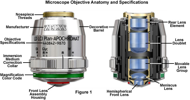
Major microscope manufacturers offer a wide range of objective designs that feature excellent optical characteristics under a wide spectrum of illumination conditions and provide various degrees of correction for the primary optical aberrations. The objective illustrated in Figure 1 is a 20x multi-immersion media plan-apochromat, which contains 9 optical elements that are cemented together into two groups of lens doublets, a movable lens triplet group, and two individual internal single-element lenses. The objective also has a hemispherical front lens and a meniscus second lens, which work synchronously to assist in capturing light rays at high numerical aperture with a minimum of spherical aberration. Many high magnification objectives are equipped with a spring-loaded retractable nosecone assembly that protects the front lens elements and the specimen from collision damage. Internal lens elements are carefully oriented and tightly packed into a tubular brass housing that is encapsulated by the decorative objective barrel. Specific objective parameters such as numerical aperture, magnification, optical tube length, degree of aberration correction, and other important characteristics are imprinted or engraved on the external portion of the barrel. The objective featured in Figure 1 is designed to operate utilizing water, glycerin, or a specialized hydrocarbon-based oil as the imaging medium.
Georeferencing an analog or digital photograph is dependent on the interior geometry of the sensor as well as the spatial relationship between the sensor platform and the ground. The single vertical aerial photograph is the simplest case; we can use the internal camera model and six parameters of exterior orientation (X, Y, Z, roll, pitch, and yaw) to extrapolate a ground coordinate for each identifiable point in the image. We can either compute the exterior orientation parameters from a minimum of 3 ground control points using space resection equations, or we can use direct measurements of the exterior orientation parameters obtained from GPS and IMU.
The internal geometry of images captured by spaceborne scanning systems is much more complex. Across-track scanning and whiskbroom systems are more akin to a lidar scanner than to a digital area array imager. Each pixel is captured at a unique moment in time; the instantaneous position of the scanning device must also be factored into the image rectification. For this reason, a unique (and often proprietary) sensor model must be applied to construct a coherent two-dimensional image from millions of individual pixels. Add to this complexity the fact that there is actually a stack of recording elements, one for each spectral band, and that all must be precisely co-registered pixel-for-pixel to create a useful multiband image.
In many biological and petrographic applications, when mounting the specimen, a glass coverslip is used to both protect the integrity of the specimen and to provide a clear window for observation. The coverslip acts to converge the light cones originating from each point in the specimen. But it also introduces chromatic and spherical aberration that must be corrected by the objective. The refractive index, dispersion, and thickness of the coverslip determine the degree to which light rays are converged. An additional concern is the aqueous solvent or excess mounting medium that lies between the specimen and coverslip in wet or thickly mounted preparations, which add to the variations in refractive index and thickness of the cover slip.
A majority of the microscope objectives being produced today offer extraordinarily low degrees of aberration and other imperfections, assuming the appropriate objective is selected and utilized properly. Even still, the microscopist must be conscious of the fact that objectives are not perfectly crafted from every standpoint, but are designed to meet a certain set of qualifications depending on intended use, constraints on physical dimensions, and price ranges. Consequently, objectives are made with degrees of correction that differ for chromatic and spherical aberration, field size and flatness, transmission wavelengths, freedom from fluorescence, birefringence, and additional factors contributing to background noise. Additionally, they are intended to be used under certain limited conditions, such as with particular tube lengths and tube lenses, type and thickness of immersion media and coverslips, wavelength ranges, field sizes, ocular types, and special condensers.
Multispectralimagingin agriculture
Since the 1967 inception of the Earth Resource Technology Satellite (ERTS) program (later renamed Landsat), mid-resolution spaceborne sensors have provided the vast majority of multispectral datasets to image analysts studying land use/land cover change, vegetation and agricultural production trends and cycles, water and environmental quality, soils, geology, and other earth resource and science problems. Landsat has been one of the most important sources of mid-resolution multispectral data globally. The history of the program and specifications for each of the Landsat missions is covered in Chapter 6 of Campbell (2011).
Author: Rakesh Malhotra, John A. Dutton e-Education Institute, College of Earth and Mineral Sciences, The Pennsylvania State University Penn State Professional Masters Degree in GIS: Winner of the 2009 Sloan Consortium award for Most Outstanding Online Program
Finally, the last but perhaps most important factor in determining the resolution of an objective is the angular aperture, which has a practical upper limit of about 72 degrees (with a sine value of 0.95). When combined with refractive index, the product:
The rear aperture or exit pupil of the objective restricts the light rays as they pass through an objective. The diameter of this aperture varies between 12 millimeters for low magnification objectives down to around 5 millimeters for the highest power apochromatic objectives. Close consideration of aperture size is absolutely imperative for epi-illumination applications that rely on the objective to act as both an imaging system and condenser, where the exit pupil also becomes an entrance pupil. The image of the light source must entirely fill the objective rear aperture to produce even illumination across the viewfield. If the light source image is smaller than the aperture, the viewfield will experience vignetting from uneven illumination. Conversely, if the light source image is larger than the rear aperture, all of the light will not enter the objective and the intensity of illumination is reduced.
For many years, field curvature went uncorrected as the most severe optical aberration that occurred in fluorite (semi-apochromat) and apochromat objectives, tolerated as an unavoidable artifact. The introduction of flat-field (plan) correction to objectives perfected their use for photomicrography and video microscopy, and today these corrections are standard in both general use and high-performance objectives. Figure 3 illustrates how correction for field curvature (for a simple achromat) adds a considerable number of lens elements to the objective. The significant increase in lens elements for plan correction also occurs with fluorite and apochromat objectives, frequently resulting in an extremely tight fit of lens elements (see Figure 1) within the internal objective sleeve.
where Resolution is the minimum separation distance between two point objects that are clearly resolved, λ is the illumination wavelength, n is the imaging medium refractive index, and θ is equal to one-half of the objective angular aperture. With this in mind, it is apparent that resolution is directly proportional to the illumination wavelength. The human eye responds to the wavelength region between 400 and 700 nanometers, which represents the visible light spectrum that is utilized for a majority of microscope observations. Resolution is also dependent upon the refractive index of the imaging medium and the objective angular aperture. Objectives are intended to image specimens either through air or a medium of higher refractive index between the front lens and the specimen. The field of view is often highly restricted, and the front lens element of the objective is placed close to the specimen with which it must lie in optical contact. A gain in resolution by a factor of about 1.5 is attained when immersion oil is substituted for air as the imaging medium.
Digital Globe (QuickBird and WorldView) and GeoEye (IKONOS and OrbView) collect high-resolution multispectral imagery which is sold commercially to users throughout the world. US Department of Defense users and partners have access to these datasets through commercial procurement contracts; therefore, these satellites are quickly becoming a critical source of multispectral imagery for the geospatial intelligence community. Bear in mind that the trade-off for high spatial resolution is limited geographic coverage. For vast areas, it is difficult to obtain seamless, cloud-free, high-resolution multispectral imagery within the single season or at the particular moment of the phenological cycle of interest to the researcher.
Multi spectral imagingcamera
2217 Earth and Engineering Sciences Building, University Park, Pennsylvania, 16802 Contact Us Privacy & Legal Statements | Copyright Information The Pennsylvania State University © 2023
Multispectral images in Remote sensing
Digital aerial cameras were developed to replicate and improve upon the capabilities of film cameras; therefore, most commercially available medium and large-format mapping cameras produce panchromatic, natural color, and color-infrared imagery. They are, in fact, multispectral remote sensing systems. Most are based on two-dimensional area arrays. The Leica Geosystems ADS-40, which makes use of linear array technology, is the exception. This sensor was described in some detail in Lesson 2. The unique design of this instrument allows it to capture stereoscopic imagery in a single pass, but georeferencing of the linear array data is more complex than for a frame image.
One of the most significant improvements in objective design during recent years is the enhancement of antireflection coating technology, which aides in reducing unnecessary reflections that occur as light passes through the lens system. Each uncoated air-glass interface is capable of reflecting between four and five percent of an incident light beam normal to the surface, resulting in a transmission value of 95-96 percent at normal incidence. If a quarter-wavelength thick antireflection coating with the appropriate refractive index is applied, it can increase this value by three to four percent. Multilayer coatings, which produce transmission values exceeding 99.9 percent in the visible spectral range, have replaced the single-layer lens coatings once used to reduce glare and improve transmission.
For several years, most manufacturers conformed to an international standard of parfocal distance when designing objective lenses for biological applications. As a result, a majority of objectives had a parfocal distance of 45.0 millimeters and were considered interchangeable. As it became commonplace to produce infinity-corrected tube lengths, a new set of design criteria was created to correct for aberrations in the objective and tube lenses. Alongside a demand for greater flexibility to accommodate the requirement of expanding working distances with higher numerical apertures and field sizes, interchangeability between objective lenses from different manufacturers is now more limited.
Multispectralimagingskin
Just as the brightness of illumination in a microscope is directed by the square of the working numerical aperture of the condenser, the brightness of an image produced by the objective is determined by the square of its numerical aperture. Additionally, objective magnification also plays a role in determining image brightness, which is inversely proportional to the square of the lateral magnification. The square of the numerical aperture/magnification ratio expresses the light-gathering power of the objective when used with transmitted illumination. High numerical aperture objectives collect more light and produce a brighter, more corrected image that is highly resolved because they also are often better corrected for aberration. In cases where the light level is a limiting factor (image brightness decreases rapidly as the magnification increases), choose an objective with the highest numerical aperture with the lowest magnification factor capable of producing sufficient resolution.
This courseware module is offered as part of the Repository of Open and Affordable Materials at Penn State. Except where otherwise noted, content on this site is licensed under a Creative Commons Attribution-NonCommercial-ShareAlike 4.0 International License. The College of Earth and Mineral Sciences is committed to making its websites accessible to all users, and welcomes comments or suggestions on access improvements. Please send comments or suggestions on accessibility to the site editor. The site editor may also be contacted with questions or comments about this Open Educational Resource.
In situations where the specimen is designed to be imaged without a coverslip, the working distance is measured at the actual surface of the specimen. Working distance typically decreases in a series of matched objectives as the magnification and numerical aperture increase. Objectives intended to view specimens with air as the imaging medium should have comparatively long working distances providing that numerical aperture requirements are satisfied. Alternatively, immersion objectives should have shallower working distances in order to keep the immersion liquid between the front lens and the specimen in place. Many objectives designed with similar working distances have a spring-loaded retraction stopper that allows the front lens assembly to be withdrawn by pushing it into the objective body and twisting to secure its place. Twisting the retraction stopper in the opposite direction releases the lens assembly for use. In some applications (see below), a long free working distance is indispensable, and special objectives are designed for such use despite how difficult it is to achieve large numerical apertures and the necessary degree of optical correction.
Several airborne systems, the Leica ADS-40 and the ITRES CASI, SASI, and TABI, also employ the pushbroom design. Each line of imagery is captured at a unique moment in time, corresponding with an instantaneous position and attitude of the aircraft. When direct georeferencing is integrated with these sensors, each single line of imagery has the exterior orientation parameters needed for rectification. However, without direct georeferencing, it is impossible to reconstruct the image geometry; the principles of space resection only apply to a rigid two-dimensional image.
Except where otherwise noted, content on this site is licensed under a Creative Commons Attribution-NonCommercial-ShareAlike 4.0 International License.
The John A. Dutton Institute for Teaching and Learning Excellence is the learning design unit of the College of Earth and Mineral Sciences at The Pennsylvania State University.
The most important imaging component in the optical microscope is the objective, a complex multi-lens assembly that focuses light waves originating from the specimen and forms an intermediate image that is subsequently magnified by the eyepieces. Objectives are responsible for primary image formation and play a central role in establishing the quality of images that the microscope is capable of producing. Furthermore, the magnification of a particular specimen and the resolution under which fine specimen detail also heavily depends on microscope objectives. The most difficult component of an optical microscope to design and assemble, the objective is the first element that light encounters as it passes from the specimen to the image plane. Objectives received name from the fact that they are, by proximity, the closest component to the object, or specimen, being imaged.
It is possible to correct for variations in coverslip thickness. Several high-performance apochromat dry objectives are fitted with correction collars that allow adjustment by a rotating collar, which causes two of the lens element groups in the objective to move closer together or farther apart (see Figure 4). Various specialized phase contrast objectives that are designed for tissue culture observation with an inverted microscope have an even broader compensation range of between 0 to 2 millimeters. In this way, specimens can be viewed through the bottom of most culture vessels, which in this size range, often have dramatic thickness fluctuations.
The imaging medium between the objective front lens and the specimen cover slip is another important element in respect to correction for spherical aberration and coma in the design of lens elements for objectives. Lower power objectives are designed to be used with only air as the imaging medium between the objective front lens and the coverslip. The maximum theoretical numerical aperture obtainable with air is 1.0, however in practice it is virtually impossible to produce a dry objective with a numerical aperture above 0.95. The effect of coverslip thickness variation is negligible for dry objectives having numerical apertures less than 0.4, but such deviation becomes significant at numerical apertures exceeding 0.65, where fluctuations as small as 0.01 millimeter can introduce spherical aberration.
A linear array, or pushbroom scanner, is used in many spaceborne imaging systems, including SPOT, IRS, QuickBird, OrbView, and IKONOS. The position and orientation of the sensor are precisely tracked and recorded in the platform ephemeris. However, other geometric distortions, such as skew caused by the rotation of the earth, must be corrected before the imagery can be referenced to a ground coordinate system.
is known as the numerical aperture (NA), and provides an important indicator of the resolution for any particular objective. Other than magnification, numerical aperture is generally the most important design criteria when considering which microscope objective to choose. Values range from 0.025 for very low magnification objectives (1x to 4x) to as much as 1.6 for high-performance objectives that employ specialized immersion oils. As numerical aperture values increase for a series of objectives of the same magnification, a greater light-gathering ability and increase in resolution occurs. Under the best circumstances, detail that is just resolved should be enlarged sufficiently to be viewed with comfort, but not to the point that empty magnification obstructs observation of fine specimen detail. The microscopist should carefully choose the numerical aperture of an objective to match the magnification produced in the final image. Magnifications higher than this value will yield no additional useful information (or finer resolution of image detail), and will lead to image degradation. Exceeding the limit of useful magnification causes the image to suffer from empty magnification, where increasing magnification will simply cause the image to become more magnified with no corresponding increase in resolution.
Older objectives typically have lower numerical apertures, and are subject to chromatic difference of magnification, an aberration that requires correction by the use of specially designed compensating oculars or eyepieces. This type of correction was prevalent during the popularity of fixed tube length microscopes, but is not necessary with modern infinity-corrected objectives and microscopes. Recently, correction for chromatic difference of magnification is either built into the modern microscope objectives themselves (Olympus and Nikon), or corrected in the tube lens (Leica and Zeiss). The intermediate image in an infinity-corrected system appears behind the tube lens in the optical pathway at the reference focal length. The tube lens focal length varies between 160 and 250 millimeters, depending upon design constraints imposed by the manufacturer. By dividing the reference focal length by the focal length of the objective lens, the magnification of an infinity-corrected objective can be calculated.
The French SPOT satellites have been another important source of high-quality, mid-resolution multispectral data. The imagery is sold commercially, and is significantly more expensive than Landsat. SPOT can also collect stereo pairs; images in the pair are captured on successive days by the same satellite viewing off-nadir. Collection of stereo pairs requires special control of the satellite; therefore, the availability of stereo imagery is limited. Both traditional photogrammetric terrain extraction techniques, as well as automatic correlation, can be used to create topographic data in inaccessible areas of the world, especially where a digital surface model may be an acceptable alternative to a bare-earth elevation model.
A dramatic improvement in contrast and transmission of visible wavelengths is the result of most microscope manufacturers currently producing their own proprietary formulations, along with a simultaneous destructive interference in harmonically-related frequencies lying outside the transmission band. The microscopist should be aware of the fact that these specialized coatings can be easily damaged by mis-handling. A good rule to employ in order to distinguish between coatings is that multilayer antireflection coatings have a slightly greenish tint, as opposed to the purplish tint of single-layer coatings. Also, the surface layer of antireflection coatings used on internal lenses is often much softer than corresponding coatings. Special care should be taken when cleaning optical surfaces that have been coated with thin films, especially if the microscope has been disassembled and the internal lens elements are subject to inspection.
The origins of commercial multispectral remote sensing can be traced to interpretation of natural color and color infrared (CIR) aerial photography in the early 20th century. CIR film was developed during World War II as an aid in camouflage detection (Jensen, 2007). It also proved to be of significant value in locating and monitoring the condition of vegetation. Healthy green vegetation shows up in shades of red; deep, clear water appears dark or almost black; concrete and gravel appear in shades of grey. CIR photography captured under the USGS National Aerial Photography Program was manually interpreted to produce National Wetlands Inventory (NWI) maps for much of the United States. While film is quickly being replaced by direct digital acquisition, most digital aerial cameras today are designed to replicate these familiar natural color or color-infrared multispectral images.
Multispectralimagingsatellites
The most common objectives used on laboratory microscopes are the achromatic objectives. Such objectives are corrected for axial chromatic aberration in blue and red wavelengths, which are about 486 and 656 nanometers, respectively. Both are brought into a single common focal point. Achromatic objectives are also corrected for spherical aberration in the color green (546 nanometers; see Table 1). Achromatic objectives' limited correction can result in images with a magenta halo if focus is chosen in the green region of the spectrum. The lack of correction for flatness of field (or field curvature) presents a further problem. Plan achromats provide flat-field corrections for achromat objectives (Figure 2). An even higher level of correction and cost is found in objectives called fluorites or semi-apochromats (illustrated by center objective in Figure 2), named for the mineral fluorite, which was originally used in their construction.
The third type of objective, the apochromatic objective, possesses the highest level of correction (Figure 2). Lower power apochromat objectives (5x, 10x, and 20x) have a longer working distance than higher power (40x and 100x) apochromat objectives. Apochromats almost eliminate chromatic aberration, are usually corrected chromatically for three colors (red, green, and blue), and are corrected spherically for either two or three wavelengths (see Table 1). Apochromatic objectives are the best choice for color photomicrography in white light. Because of their high level of correction, apochromat objectives usually have, for a given magnification, higher numerical apertures than do achromats or fluorites. Many of the newer high-performance fluorite and apochromat objectives are corrected for four (dark blue, blue, green, and red) or more colors chromatically and four colors spherically.
The College of Earth and Mineral Sciences is committed to making its websites accessible to all users, and welcomes comments or suggestions on access improvements. Please send comments or suggestions on accessibility to the site editor. The site editor may also be contacted with questions or comments about this Open Educational Resource.
The ADS-40 and the Z/I Digital Modular Camera (DMC) are being used extensively in the USDA NAIP program to capture high-resolution multispectral data over most of the conterminous United States each growing season. Be aware, however, that NAIP data, other than the fact that it is orthorectified to National Digital Orthophoto Program (NDOP) standards, is not extensively processed or radiometrically calibrated. The USDA uses it primarily for visual verification and interpretation, not for digital classification.


 Ms.Cici
 8618319014500