
Gaussian beams and lasers - Book chapter - gaussian laser
Consequently, what are Tolerance precautions that should be considered for CNC Machining? There are numerous significant aspects to consider while calculating tolerances. These are discussed below;
The average texture of a part’s surface is measured by surface roughness. The surface roughness that is compatible with the tolerance level is the most usually used. The smaller the dimensional accuracy requirements for mechanical components, the lower the surface roughness value of the mechanical parts, however, there is no permanent function link between them under normal circumstances.
The other is used in typical precision equipment that requires high fit stability, a mechanical component wear limit of no more than 25% of the machined part’s dimensional accuracy, and a very close contact surface. Machines, tools, surfaces that work with rolling bearings, taper pinholes, and contact surfaces that move at quite fast speeds are all examples of its application.
Form tolerance standards are used to regulate the derived items because points from the derived feature cannot be sampled directly. These points must be computed using sampled points from the outside. But, how can you choose tolerance for CNC machining?
STM operates on a simple basis. A sharp metal point (one electrode of the tunnel junction) is brought close enough to the surface to be probed (second electrode) that the tunnelling current varies from 0.2 to 10 nA, which is quantifiable at a convenient working voltage (10 mV to 2 V). At a distance of 0.3 to 1 nm, the tip is scanned across a surface while the tunnel current between the tip and the surface is measured.
Computer Numerical Control (CNC) machining demands extreme accuracy. In this profession, even millimeters can lead to major mistakes. Unfortunately, no machine can guarantee 100 percent accuracy all the time.
To enable further innovation in chip manufacturing, we developed a next-generation EUV platform that increases the numerical aperture (NA) from 0.33 to 0.55 (‘High NA’). The platform, called ‘EXE’, has a novel optics design and significantly faster wafer and reticle stages.
There is a wide variety of equipment available for roughness measurement. But, here are two broad techniques to determine roughness.
The dual-stage extreme ultraviolet (EUV) lithography system is the first in a new generation of machines that will provide 8 nm resolution to support advanced Logic and Memory chip production.
The EXE platform will support high-volume chip manufacturing in 2025–2026, enabling geometric chip scaling into the next decade. That will include future advanced nodes, starting at the 2 nm Logic node and followed by Memory nodes at a similar density. By reducing the number of process steps in high-volume manufacturing, chipmakers will benefit from significant reductions in defects, cost and cycle time.
Jul 15, 2021 — Windows Hello face authentication utilizes a camera specially configured for near infrared (IR) imaging to authenticate and unlock Windows ...
This technique utilises the capacitance approach based on the parallel capacitor idea. The capacitance between two conducting elements is related to their area and the medium’s dielectric constant, but is inversely proportional to their separation. It’s rather simple to calculate the effective capacitance between a rough surface and a smooth surface disc for various deterministic models. It’s thought of as the sum of a number of small elemental areas at varying heights. Surface roughness affects the capacitance between a smooth disc surface and the surface to be measured. Based on this premise, a commercial instrument is available. Continuous inspection processes also employ the capacitance method.
Every feature on a component has a size and a geometrical shape. The function of the part involves constraints for size and geometrical attributes (shape, orientation, and placement) variations, which when surpassed, damage this function. Most inspectors use the minimum zone solution to calculate form tolerances, which minimizes the maximum error between data points and a reference feature.
The first High NA EUV lithography system was delivered in December 2023. The platform will support process development and is expected to be used in high-volume manufacturing in 2025–2026.
Extreme UVmeaning
A non-contact optical profiler based on the principle of two-beam optical interferometry invented in 1983 and is now commonly used to measure smooth surfaces in the electronics and optical sectors. An atomic force microscope, which is essentially a nano-profiler that operates at ultra-low loads, was created in 1985. Surface roughness can be measured with lateral resolution varying from microscopic to atomic scales.
The wafer stage positions the wafer to within a quarter of a nanometer for each exposure, checking and adjusting 20,000 times per second.
Some machine shops require tolerances from customers, and if these are not provided, they will either refuse to work on the component or use a standard tolerance of, say, ±0.005’’ (0.127 mm). The tolerance may be larger or smaller than 0.005.
Extremeultraviolet lithography
Variations may happen due to a variety of causes, ranging from the part’s material to the machining process utilised. This is why parts are given machining tolerances throughout the design phase – an amount of permissible variation in a part’s dimension.
There are various elements to consider when choosing the appropriate surface roughness for your project. Depending on the product’s application, the desired durability, whether the item will be polished or painted, the importance of accurate dimensions, and the project’s budget, the roughness average (Ra) may need to be higher or lower.
From the time it was first lit in 1870 until it was decommissioned in 1933, Mission Point Lighthouse had a 5th Order Fresnel Lens. The light from this lens can ...
Ultravioletlightexamples
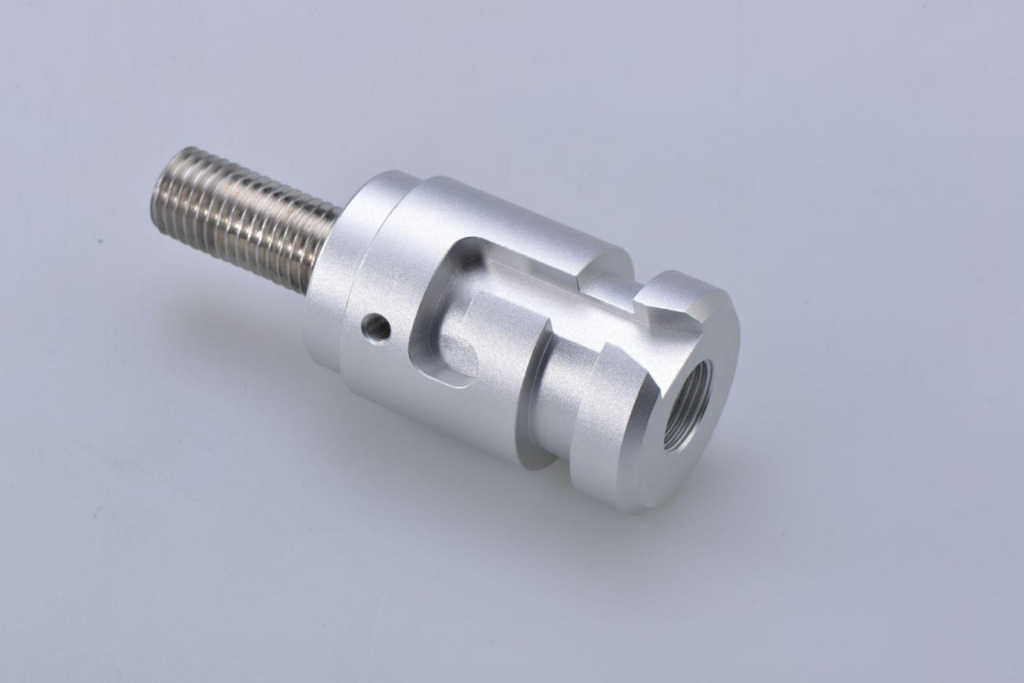
Surface roughness in CNC machining has an impact on how the created object interacts with its surroundings. A typical ‘as machined’ CNC machining finish is smooth to the touch with an average roughness (Ra3.2), but visible machining lines from the cutting tool are visible. Most parts can be made with this amount of roughness, although in some cases a smoother surface is necessary. When developing sliding parts, a smoother surface might be advantageous since it reduces friction between parts and improves wear performance.
When you actually read it. You will notice that the same empirical formula is used with different values. It may cause confusion for the people who have very limited knowledge in this area. Simultaneously, it makes selecting surface roughness in the work of mechanical parts more complex.
Tolerances are chosen according to the production process. Typically, the higher the tolerance, the lower the cost. Excessive tolerance selection carries the risk of prospective and actual performance breakdowns, service deterioration, functional undesirableness, and poor looks. Limit tolerancing is the most practical and widely used. It allows for the arbitrary selection of tolerances for a chain of measurements and ensures a good fit, but it does not take production costs into account.
Basically, the International Organization for standardization (ISO 2768) standard is broken into two parts, each of which aims to simplify drawings by establishing precision levels as general rules:
Surface roughness is an important technical indicator that reflects the micro-geometric error of the machining part’s surface and is the primary basis for inspecting the surface quality of machining parts; whether it is reasonable or not, it is directly related to the machining parts’ quality, service life, and production cost. Surface roughness refers to the finely spaced micro-irregularities on the surface texture, which is made up of three elements: roughness, waviness, and form.

It means that the surface roughness requirements are high but the dimensional tolerance requirements are low. Under typical circumstances, the tolerance level and the surface roughness value of CNC machining items with dimensional tolerance requirements have a reasonable relationship.
Leading-edge microchips contain billions of transistors. With each new generation (often referred to as a ‘node’), chipmakers pack in ever more and tinier transistors to make the chips more powerful, faster and energy efficient. Chips made with EUV lithography are enabling smart technology (cars, phones and homes), augmented reality, artificial intelligence and much more.
The third type is primarily used in general machinery where the wear limit of mechanical parts must not exceed 50% of the dimensional tolerance value and there are no contact surfaces for relative moving parts, likewise tight surfaces, keys, and keyways’ working surface; contact surface with low relative movement speed as well as a bracket hole, bushing, working surface with a hole for the wheel shaft, reducer, and so on.
Extreme UVweather
Oct 3, 2014 — Contrast is a digital marketing principle that refers to using color to draw attention to specific elements on your page, such as a call to ...
But what are the different types of machining and how can you get started? Let’s look into this expanding field. The following three types are represented in the existing mechanical parts design manual:
NXE lithography systems are used in high-volume manufacturing of advanced Logic and Memory chips. The first systems to use ASML’s novel 13.5 nm EUV light source, they print microchip features with a resolution of 13 nm, which is unreachable with deep ultraviolet (DUV) lithography. Chipmakers use our NXE systems to print the highly complex foundation layers of their 7 nm, 5 nm and 3 nm nodes. Read about how EUV lithography went from imagination to reality.
Computer numerical control (CNC) machining service can maintain control over the parts’ tolerances. The higher the manufacturing industry’s accuracy standards, the smaller the tolerance value. The bigger the tolerance, on the other hand, the wider and lower the needed accuracy. When particular surface roughness values are required, post-processing methods are rarely used. This is because these processes are difficult to manage and can influence part dimensional tolerance.
Overall assessment may be performed with an optical microscope, which only gives qualitative data. Geometrical and physical approaches are two types of optical methods. Taper sectioning and light sectioning are two geometrical approaches. Specular and diffuse reflections, speckle patterns, and optical interference are examples of physical approaches.
But, How do surface roughness and tolerance level correlate with each other in CNC machining? In order to know, keep on reading to explore this relationship. Before we move ahead it’s important to know the methods for surface roughness measurement.
Then, in 2010, the first TWINSCAN NXE:3100, a pre-production EUV system, was shipped to one of our major customers. Two years later, six more systems were shipped to different customers. The first EUV production system – the TWINSCAN NXE:3300 – was shipped in 2013, signaling another step forward in the development of this new technology.
The AFM combines the STM with the stylus profiler’s principles. To perceive the proximity of the tip to the sample in the AFM, the force between the sample and the tip is sensed rather than the tunnelling current. Moving the sample using piezoelectric scanners brings a sharp tip at the end of a cantilever into contact with a sample surface. This mode of functioning is known as “repulsive mode” or “contact mode”. Atomic force microscopy is a nano-profiler that can work with very small samples. This approach determines the surface roughness with lateral resolution ranging from microscopic to atomic scales. This method is most commonly used to scale roughness with a very high lateral resolution, such as nanoscale roughness.
Both reflection and replica electron microscopy may reveal macroscopic and microscopic surface characteristics. However, they have two main drawbacks: first, quantifiable data is difficult to obtain; and second, because of their intrinsically limited field of vision, they only display a few asperities, whereas the important point about surface contact is that it involves vast populations of interacting asperities.
Under the same dimensional tolerances, the requirements for surface roughness of their CNC machining parts vary depending on the machine. This is the issue of cooperation’s stability. The criteria for the stability and interchangeability of machined parts vary in the design and fabrication of mechanical parts for various types of machines.
As an illustration, a drawing could be designated as International Organization for standardization ISO 2768-mK, which means it must adhere to the tolerance limits for Part 1’s “medium” and Part 2’s “K” tolerance classes. You can simplify your drawing by including the ISO 2768 specification and avoid specifying tolerances for each dimension and feature.
If a standard zoom lens isn't quite strong enough for your needs, then the next step up is a telephoto lens. These big lenses are found within a range of 100mm ...
by R Paschotta · Cited by 2 — Polarization refers to the electric field oscillation direction of light, with various states like linear, circular, elliptical, radial, and azimuthal.
EUV systems use several multilayer mirrors instead of lenses to guide the EUV light to the wafer, shrinking the reticle pattern by a factor of four.
Precision robot arms transfer wafers in and out of the system’s vacuum environment through an air lock, operating within a positioning accuracy of 25 µm and a uniform surface temperature within 2 mK.
Whereas, the American Society of Mechanical Engineers(ASME Y14. 5) standard specifies geometric dimensioning and tolerancing symbols, definitions, and regulations. The standard’s purpose is to ensure that detailed information is provided clearly all across the design and manufacturing process for mechanical components.
This equipment is often used in research to quantify extremely high lateral resolution roughness, especially nanoscale roughness. There are a number of other procedures demonstrated in the lab but never commercially deployed, or that have been used in specialized applications. Based on the physical principle involved, we’ll classify the various techniques into six categories:
Extremeultraviolet lithography machine
Well, the Geometric dimension and tolerance (GD&T Y14.5 Standard) is helpful for designers and manufacturers to communicate tolerance information. Unfortunately, there is currently no standard for verifying tolerance specifications.
Using extreme ultraviolet (EUV) light, our NXE and EXE systems deliver high-resolution lithography and make mass production of the world’s most advanced microchips possible
If the smaller the dimensional accuracy requirements for mechanical components, then lower the surface roughness value of the mechanical parts. However, there is no established functional link between them under normal circumstances. Some machinery and instruments have very smooth surface requirements for example; handles, handwheels, sanitary equipment, food machinery, and mechanical parts with a changed surface.
As we know, tolerance is the control of the correctness of CNC machined parts. There are standard tolerances for CNC machined items such as threads, cuts, and pipes. Standard tolerances are required for numerically controlled machined parts for a variety of applications. When the customer does not select the tolerance level, most CNC milling services provide ±0.1 mm, which is also the typical CNC machining component tolerance standard specified by the mechanical engineer. The most frequent worldwide standard organizations that set CNC machining tolerances are (ISO) International Organization for Standardization, (ASME) American Society of Mechanical Engineers, and others. Now discuss them in-depth.
These techniques are mostly employed in service for constant assessment (quality control) operations. Since they work without touching the surface and are extremely rapid. This gives numerical data that may empirically correlate to roughness. The hydraulic and pneumatic gauging methods are the two most widely employed techniques.
Buy BoliOptics Microscope Resolving Power Resolution Test Target Slide (Negative) Glass, Black RT20301101: Compound Binocular Microscopes - Amazon.com ...
This technique records and amplifies the vertical motion of the stylus on the surface to be measured at a constant speed. A stylus measurement head with a stylus tip and a scanning mechanism make up the instrument. Acquiring two-dimensional scans in the X direction while stepping in the Y direction by 5 m with the Y lead screw. It is used for precise sample positioning and yields a three-dimensional image.
It basically tells the manufacturing personnel and equipment how accurate and precise each regulated feature of the part needs to be. On engineering drawings and computer-generated three-dimensional solid models, the Geometric and Dimensions Tolerance (GD&T) use a symbolic language that expresses nominal geometry and its permissible variance.
Extreme uv lightuses
The standard methods for determining tolerances do not directly maximize costs and tolerances. Their main focus is defining tolerances so that the design may work first and, preferably, be the cheapest.
EUV light is absorbed by everything, even air. So the whole light path and everything the light interacts with – from source to wafer – must be in high vacuum.
When soldering small surface-mount (SMD/SMT) components, one thing you'll need is a good pair of tweezers. These tweezers are a great pair of every-day ...
To generate EUV light, a CO2 laser fires two separate laser pulses at a fast-moving drop of tin. This vaporizes the tin and creates EUV light. It does this up to 50,000 times per second.
The International Organization for Standardization (ISO) and the American Society of Mechanical Engineers (ASME) are the two most common international standard organizations that determine CNC machining tolerances. A common ‘as machined’ CNC machining finish is smooth to the touch with an average roughness (Ra3.2). If these are not available, a standard tolerance is used as ± 0.005″ (0.127 mm).
Though there were delays and difficulties, EUV lithography turned a corner in 2016. Customers began ordering the NXE:3400 in higher numbers. At the beginning of 2020, we celebrated the 100th EUV system shipment.
Researchers and scientists first began to explore EUV lithography in the 1980s, with the first successful applications of this new technology occurring toward the end of the decade.
EXE, or ‘High NA’, systems are the latest generation in EUV lithography. With a numerical aperture (NA) of 0.55, their innovative new optics provide higher contrast and print with a resolution of just 8 nm.
The first is mostly employed in precision machinery that requires a high level of fit stability. During service or after continuous assembly, the wear limit of machined parts must not exceed 10% of the dimensional tolerance of the parts. This is mostly utilised on the friction surfaces of extremely essential machined parts, like the inner surface of the cylinder, the spindle neck of precision machine tools, the spindle neck of coordinate boring machines, and more precise bits that suit highly particular requirements.
→ In a microscope, the field of view (FOV) is the diameter of the circle of light that you see when looking through a microscope. FOV = diameter of circle ...
The measurement method that is ultimately chosen is highly dependent on the user’s application. Measurement methods based on specular reflection, diffuse reflection, or speckle pattern are utilised for in-process inspection operations. Fluid or electrical technologies could be employed for continuous inspection (quality control) activities that need minimum information.
EUV lithography makes scaling more affordable for chipmakers and allows the semiconductor industry to continue its pursuit of Moore’s Law. EUV systems are used to print the most intricate layers on a chip, with the rest of the layers printed using various DUV systems. Both types of technology will be required in parallel for many years to come and we’re continuing to advance both technologies.
Extreme uv lightlithography
To ensure that the aspects of size and geometry of all features are regulated, the tolerancing on the drawing should be complete, i.e. nothing should be assumed or left to judgment in the workshop or inspection department. The use of general size and geometry tolerances makes it easier to ensure that this requirement is met.
According to some mechanical components design manuals and monographs, there are a lot of calculation formulas available. It represents the relationship between the surface roughness and the dimensional tolerances of mechanical parts. You can read the formula list to choose from.
Engineering EUV was anything but simple. ASML invested more than €6 billion in EUV R&D over 17 years. We acquired Cymer – a company specialized in light source technology – to accelerate EUV source development. And once the technology was developed, we had to overcome numerous technical challenges to meet chipmaker’s requirements for high-volume manufacturing.
Extreme UVwavelength
Reticles contain the chip pattern to be printed on the wafer. In EUV, reticles are multilayer reflectors that use interference to reflect light from the pattern.
4X w/ 2'FocalLength Plastic Handled Lightweight Magnifier. Handheld Magnifier. Fastenal Sku: 3119798. User Icon Sign In to view pricing. -. +. ADD TO CART ...
But EUV was a challenging and costly pursuit and, in time, only ASML – with our partners and suppliers – continued work toward a viable system. In August 2006 we shipped the world’s first EUV lithography demo tool to the College of Nanoscale Science & Engineering in Albany, in the US, and to imec in Leuven, Belgium. The college and company used these prototypes to learn about EUV and how it might fit into the semiconductor manufacturing process.
The standard is formed of general guidelines because there are situations when a dimension of a part requires a tighter tolerance than those defined by ISO 2768. Such occurrences are common, therefore review the drawing title block for general tolerance requirements and make a note of any special part specifications or project requirements.
Work to industrialize the technology kicked off in 1994, with a coalition of semiconductor industry companies (including ASML) delivering the very first prototype. This prototype proved that EUV lithography was possible, and the industry started to pursue the technology.
If you have a relatively new smartphone, one of the latest gaming consoles or a smart watch, it’s likely you’ve benefited directly from EUV lithography technology.
Scanning probe microscopies (SPM) are a group of equipment based on scanning tunnelling microscopy (STM) and atomic force microscopy (AFM). The first technique used to get a 3-dimensional image of a solid surface with atomic resolution is scanning probe Microscopy.
As previously stated, different materials and machining processes necessitate various tolerances. This means that machining tolerances aren’t exactly ‘standard.’ However, some manufacturers have established rules for specific applications.
The American national standard institute (ANSI Y14.5M-1982), established a standardized approach for the National Standard on Dimensioning and Tolerancing known as the Geometric dimension and tolerancing (GD&T Y14.5 Standard). A standardized approach for showing tolerance standards on engineering drawings are established to increase the use of tolerance specifications as a communication tool.
Let’s move to a deep analysis of these techniques. A contact form of analysis in which a component of the measurement device actually contacts the surface to be measured during the experiment. But, in contact-type measurement, a sharp stylus tip may damage the surface, especially soft surfaces. The normal loads must be low enough for these measurements such that the contact stresses do not surpass the hardness of the surface to be tested. The contact-type stylus instruments with electronic amplification are most popular today. The International Organization of Standardization (ISO) recommends that the stylus technique is commonly used for reference purposes.
So, what are machining tolerances, and why are they significant? Continue reading to find out how to choose tolerance that principle relates to CNC machining.
The eyepiece has several major functions: ○ The eyepiece serves to further magnify the real image projected by the objective. ○ In visual observation, the ...
In spite of the global financial crisis in 2008, we continued to invest in EUV. In the Spring of 2008, the College of Nanoscale Science & Engineering used their demo tool to produce the world’s first full-field EUV test chips. And in 2009, we opened the buildings that would house cleanrooms and workspaces for EUV development and production at our Veldhoven headquarters in the Netherlands.


 Ms.Cici
 8618319014500