
Fresnel Lens | - fresnel lense
Fiber opticinternet
Optimized Thermal ManagementThese fiber-coupled LEDs possess good thermal stability properties. The 34 mm long, passively cooled heat sink used in most of our fiber-coupled LEDs is in direct contact with the metal-core circuit board on which the LED is mounted. This minimizes the degradation of optical output power caused by increased LED junction temperature. Some of our fiber-coupled LEDs with a higher power output (M365FP1, M385FP1, M395FP1, M405FP1, and M660FP1) are mounted to a 50 mm long heat sink for increased heat dissipation and thermal stability.
It's easy to picture Internet users linked together by giant webs of fiber-optic cables; it's much less obvious that the world's hi-tech military forces are connected the same way. Fiber-optic cables are inexpensive, thin, lightweight, high-capacity, robust against attack, and extremely secure, so they offer perfect ways to connect military bases and other installations, such as missile launch sites and radar tracking stations. Since they don't carry electrical signals, they don't give off electromagnetic radiation that an enemy can detect, and they're robust against electromagnetic interference (including systematic enemy "jamming" attacks). Another benefit is the relatively light weight of fiber cables compared to traditional wires made of cumbersome and expensive copper metal. Tanks, military airplanes, and helicopters have all been slowly switching from metal cables to fiber-optic ones. Partly it's a matter of cutting costs and saving weight (fiber-optic cables weigh nearly 90 percent less than comparable "twisted-pair" copper cables). But it also improves reliability; for example, unlike traditional cables on an airplane, which have to be carefully shielded (insulated) to protect them against lightning strikes, optical fibers are completely immune to that kind of problem.
Optical fibers carry light signals down them in what are called modes. That sounds technical but it just means different ways of traveling: a mode is simply the path that a light beam follows down the fiber. One mode is to go straight down the middle of the fiber. Another is to bounce down the fiber at a shallow angle. Other modes involve bouncing down the fiber at other angles, more or less steep.
Photo: Fiber-optic cables are thin enough to bend, taking the light signals inside in curved paths too. Picture courtesy of NASA Glenn Research Center (NASA-GRC) and Internet Archive.
To fully support the maximum optical power of the LED you intend to drive, ensure that the max voltage and max current of the driver are equal to or greater than those of the LED.
The spectrum of each LED and associated data file can be viewed by clicking on the links in the table to the right. Multiple windows can be opened simultaneously in order to compare LEDs.
For applications where a hybrid patch cable is not practical, we can configure these fiber-coupled LEDs with FC/PC bulkheads; contact Tech Support for details.
Each fiber-coupled LED consists of a single LED that is coupled to the optical fiber using the butt-coupling technique. During this process, the fiber connector is positioned so that the end of the fiber will be as close as possible to the emitter, thereby minimizing losses at the fiber input and maximizing output power. The coupling efficiency is primarily dependent on the core diameter and the numerical aperture (NA) of the connected fiber. Larger core diameters and higher NA values give rise to reduced losses and increased output power at the end of the fiber. Additionally, high-OH content or solarization-resistant fibers are recommended for use with LED wavelengths below 400 nm (please refer to the table below for recommended patch cables).
This nice little experiment is a modern-day recreation of a famous scientific demonstration carried out by Irish physicist John Tyndall in 1870.
A fiber-optic cable is made up of incredibly thin strands of glass or plastic known as optical fibers; one cable can have as few as two strands or as many as several hundred. Each strand is less than a tenth as thick as a human hair and can carry something like 25,000 telephone calls, so an entire fiber-optic cable can easily carry several million calls. The current record for a "single-mode" fiber (that's explained below) is 178 terabits (trillion bits) per second—enough for 100 million Zoom sessions (according to fiber expert Jeff Hecht)!
For each LED, a DC2200 High-Power LED Driver was used to drive the LED over a range of preset current values. At each current value, the OSA took five scans across the LED spectrum and combined them to create an average spectrum. The OSA identified the peak wavelength by finding the highest intensity value within 50 nm of the predicted peak wavelength and then calculated a centroid wavelength as described above. Centroid wavelengths were identified every 0.05 A up to the current limit of the LED. The entire process was repeated four times for each LED. All measurements were taken with the OSA in the absolute power and high-resolution spectrometer modes (for more information on the OSA operating modes, see the full web presentation).
Fiber-optic cables carry information between two places using entirely optical (light-based) technology. Suppose you wanted to send information from your computer to a friend's house down the street using fiber optics. You could hook your computer up to a laser, which would convert electrical information from the computer into a series of light pulses. Then you'd fire the laser down the fiber-optic cable. After traveling down the cable, the light beams would emerge at the other end. Your friend would need a photoelectric cell (light-detecting component) to turn the pulses of light back into electrical information his or her computer could understand. So the whole apparatus would be like a really neat, hi-tech version of the kind of telephone you can make out of two baked-bean cans and a length of string!
Uses ofopticalfibre Physics
We're used to the idea of information traveling in different ways. When we speak into a landline telephone, a wire cable carries the sounds from our voice into a socket in the wall, where another cable takes it to the local telephone exchange. Cellphones work a different way: they send and receive information using invisible radio waves—a technology called wireless because it uses no cables. Fiber optics works a third way. It sends information coded in a beam of light down a glass or plastic pipe. It was originally developed for endoscopes in the 1950s to help doctors see inside the human body without having to cut it open first. In the 1960s, engineers found a way of using the same technology to transmit telephone calls at the speed of light (normally that's 186,000 miles or 300,000 km per second in a vacuum, but slows to about two thirds this speed in a fiber-optic cable).
Medical gadgets that could help doctors peer inside our bodies without cutting them open were the first proper application of fiber optics over a half century ago. Today, gastroscopes (as these things are called) are just as important as ever, but fiber optics continues to spawn important new forms of medical scanning and diagnosis.
The results of these measurements are provided in the table below and can be viewed by clicking on the graph icons. For each LED, the centroid wavelengths over all of the runs were averaged for each current point and plotted. To give a sense of possible variation in performance, the minimum and maximum wavelengths measured at each current point over all of the experimental runs are indicated by red error bars. At the lowest current values, the LED intensity was too weak to rise above the level of the noise and provide a reasonably accurate measurement of the wavelength. In these cases, we have omitted the affected currents from the graphs.
Cable TV companies pioneered the transition from the 1950s onward, originally using coaxial cables (copper cables with a sheath of metal screening wrapped around them to prevents crosstalk interference), which carried just a handful of analog TV signals. As more and more people connected to cable and the networks started to offer greater choice of channels and programs, cable operators found they needed to switch from coaxial cables to optical fibers and from analog to digital broadcasting. Fortunately, scientists were already figuring out how that might be possible; as far back as 1966, Charles Kao (and his colleague George Hockham) had done the math, proving how a single optical fiber cable might carry enough data for several hundred TV channels (or several hundred thousand telephone calls). It was only a matter of time before the world of cable TV took notice—and Kao's "groundbreaking achievement" was properly recognized when he was awarded the 2009 Nobel Prize in Physics.
Shooting light down a pipe seems like a neat scientific party trick, and you might not think there'd be many practical applications for something like that. But just as electricity can power many types of machines, beams of light can carry many types of information—so they can help us in many ways. We don't notice just how commonplace fiber-optic cables have become because the laser-powered signals they carry flicker far beneath our feet, deep under office floors and city streets. The technologies that use it—computer networking, broadcasting, medical scanning, and military equipment (to name just four)—do so quite invisibly.
Photo: A section of 144-strand fiber-optic cable. Each strand is made of optically pure glass and is thinner than a human hair. Picture by Tech. Sgt. Brian Davidson, courtesy of US Air Force.
Even thicker fibers are used in a medical tool called a gastroscope (a type of endoscope), which doctors poke down someone's throat for detecting illnesses inside their stomach. A gastroscope is a thick fiber-optic cable consisting of many optical fibers. At the top end of a gastroscope, there is an eyepiece and a lamp. The lamp shines its light down one part of the cable into the patient's stomach. When the light reaches the stomach, it reflects off the stomach walls into a lens at the bottom of the cable. Then it travels back up another part of the cable into the doctor's eyepiece. Other types of endoscopes work the same way and can be used to inspect different parts of the body. There is also an industrial version of the tool, called a fiberscope, which can be used to examine things like inaccessible pieces of machinery in airplane engines.
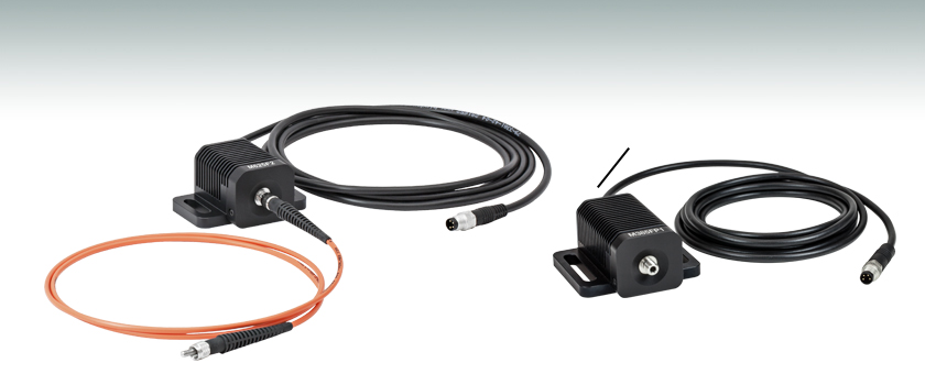
These fiber-coupled LEDs each consist of an LED mounted to a heat sink with an SMA fiber bulkhead. They can be easily integrated into an optical setup using one of our SMA-terminated multimode fiber patch cables. When the patch cable is connected to the SMA bulkhead on the LED housing, the LED will be butt-coupled to the SMA fiber connector. Hybrid patch cables can be used to transition from an SMA connector to an FC/PC connector, ferrule end, or bare fiber. For compatible drivers to power these LEDs, please see the LED Drivers tab. Please note that the minimum output powers specified below apply when the LED is used with a Ø400 µm core multimode fiber patch cable.
Artworks: Above: Light travels in different ways in single-mode and multi-mode fibers. Below: Inside a typical single-mode fiber cable (not drawn to scale). The thin core is surrounded by cladding roughly ten times bigger in diameter, a plastic outer coating (about twice the diameter of the cladding), some strengthening fibers made of a tough material such as Kevlar®, with a protective outer jacket on the outside.
Fiber-optic cables are now the main way of carrying information over long distances because they have three very big advantages over old-style copper cables:

The Romans must have been particularly pleased with themselves the day they invented lead pipes around 2000 years ago. At last, they had an easy way to carry their water from one place to another. Imagine what they'd make of modern fiber-optic cables—"pipes" that can carry telephone calls and emails right around the world in a seventh of a second!
Opticalfibre diagram
Light travels down a fiber-optic cable by bouncing repeatedly off the walls. Each tiny photon (particle of light) bounces down the pipe like a bobsleigh going down an ice run. Now you might expect a beam of light, traveling in a clear glass pipe, simply to leak out of the edges. But if light hits glass at a really shallow angle (less than 42 degrees), it reflects back in again—as though the glass were really a mirror. This phenomenon is called total internal reflection. It's one of the things that keeps light inside the pipe.

The Internet was cleverly designed to ferry any kind of information for any kind of use; it's not limited to carrying computer data. While telephone lines once carried the Internet, now the fiber-optic Internet carries telephone (and Skype) calls instead. Where telephone calls were once routed down an intricate patchwork of copper cables and microwave links between cities, most long-distance calls are now routed down fiber-optic lines. Vast quantities of fiber were laid from the 1980s onward; estimates vary wildly, but the worldwide total is believed to be several hundred million kilometers (enough to cross the United States about a million times). In the mid-2000s, it was estimated that as much as 98 percent of this was unused "dark fiber"; today, although much more fiber is in use, it's still generally believed that most networks contain anywhere from a third to a half dark fiber.
Who inventedfiberoptics
Woodford, Chris. (2006/2020) Fiber optics. Retrieved from https://www.explainthatstuff.com/fiberoptics.html. [Accessed (Insert date here)]
LEDs have relatively broad, asymmetric emission profiles. The centroid wavelength of an LED is a weighted average of the wavelength across the emission profile (following a similar concept to center of mass calculations). It is defined as
Apart from offering much higher capacity, optical fibers suffer less from interference, so offer better signal (picture and sound) quality; they need less amplification to boost signals so they travel over long distances; and they're altogether more cost effective. In the future, fiber broadband may well be how most of us watch television, perhaps through systems such as IPTV (Internet Protocol Television), which uses the Internet's standard way of carrying data ("packet switching") to serve TV programs and movies on demand. While the copper telephone line is still the primary information route into many people's homes, in the future, our main connection to the world will be a high-bandwidth fiber-optic cable carrying any and every kind of information.
Types ofoptical fiberpdf
You're reading these words now thanks to the Internet. You probably chanced upon this page with a search engine like Google, which operates a worldwide network of giant data centers connected by vast-capacity fiber-optic cables (and is now trying to roll out fast fiber connections to the rest of us). Having clicked on a search engine link, you've downloaded this web page from my web server and my words have whistled most of the way to you down more fiber-optic cables. Indeed, if you're using fast fiber-optic broadband, optical fiber cables are doing almost all the work every time you go online. With most high-speed broadband connections, only the last part of the information's journey (the so-called "last mile" from the fiber-connected cabinet on your street to your house or apartment) involves old-fashioned wires. It's fiber-optic cables, not copper wires, that now carry "likes" and "tweets" under our streets, through an increasing number of rural areas, and even deep beneath the oceans linking continents. If you picture the Internet (and the World Wide Web that rides on it) as a global spider's web, the strands holding it together are fiber-optic cables; according to some estimates, fiber cables cover over 99 percent of the Internet's total mileage, and carry over 99 percent of all international communications traffic.
The faster people can access the Internet, the more they can—and will—do online. The arrival of broadband Internet made possible the phenomenon of cloud computing (where people store and process their data remotely, using online services instead of a home or business PC in their own premises). In much the same way, the steady rollout of fiber broadband (typically 5–10 times faster than conventional DSL broadband, which uses ordinary telephone lines) will make it much more commonplace for people to do things like streaming movies online instead of watching broadcast TV or renting DVDs. With more fiber capacity and faster connections, we'll be tracking and controlling many more aspects of our lives online using the so-called Internet of things.
Driver OptionsThorlabs offers six drivers compatible with some or all of these LEDs: LEDD1B, UPLED, DC40, DC2200, DC4100, and DC4104 (the latter two require the DC4100-HUB). See the LED Drivers tab for a list of specifications, and the Specs tab for driver compatibility information. The UPLED, DC40, DC2200, DC4100, and DC4104 drivers are capable of reading the current limit from the EEPROM chip of the connected LED and automatically adjusting the maximum current setting to protect the LED.
Structure ofoptical fiber
If you'd rather listen to our articles than read them, please subscribe to our new podcast on Apple Podcasts, Spotify, Audible, Amazon, Podchaser, or your favorite podcast app, or listen below:
Photo: Fiber optics on the battlefield. This Enhanced Fiber-Optic Guided Missile (EFOG-M) has an infrared fiber-optic camera mounted in its nose so that the gunner firing it can see where it's going as it travels. Picture courtesy of US Army.
White Light and Broadband LEDOur cold white and warm white LEDs feature broad spectra that span several hundred nanometers. The difference in perceived color between these two LEDs can be described using the correlated color temperature, which indicates that the LED's color appearance is similar to a black body radiator at that temperature. In general, warm white LEDs offer a spectrum similar to a tungsten source, while cold white LEDs have a stronger blue component to the spectrum. Cold white LEDs are more suited for fluorescence microscopy applications or cameras with white balancing, because of a higher intensity at most wavelengths compared to warm white LEDs.
The CON8ML-4 connector can be used to mate mounted LEDs featured on this page to user-supplied power supplies. We also offer a male 4-Pin M8 connector cable (item # CAB-LEDD1).
All LEDs will show some variation in their spectral profile and peak wavelength as a function of the drive current. For our fiber-coupled LEDs, we used an Optical Spectrum Analyzer (OSA) to track this wavelength shift as the current of the LED was increased from near zero to the maximum current.
Optical fiber opticcable
Please note that the connectors on these fiber-coupled LEDs are intended for SMA connectors only. To prevent mechanical damage to the LED, the ferrule length of the attached connector must not exceed the maximum length for SMA connectors of 9.812 mm as defined by the EN61754-22:2005 standard.
Pin ConnectionThe diagram to the right shows the male connector of the fiber-coupled LED assembly. It is a standard M8 x 1 sensor circular connector. Pins 1 and 2 are the connection to the LED. Pins 3 and 4 are used for the internal EEPROM (electrically erasable programmable read-only memory) in these LEDs. If using an LED driver that was not purchased from Thorlabs, be careful that the appropriate connections are made to Pin 1 and Pin 2 and that you do not attempt to drive the LED through the EEPROM pins.
where I(λ) is the intensity at each wavelength, λ. As a result, we chose to follow each LED's centroid wavelength as the current was varied in order to capture effects of both the peak wavelength shift and any changes to the overall spectral profile. The OSA's Peak Track mode will automatically calculate the centroid wavelength of a spectral peak, using a user-set lower intensity limit to determine the upper and lower limits (λ2 and λ1) of the wavelength range included in the calculation. In our case, we set the lower limit to 6 dB below the peak intensity.
One characteristic of LEDs is that they naturally exhibit power degradation with time. Often this power degradation is slow, but there are also instances where large, rapid drops in power, or even complete LED failure, occur. LED lifetimes are defined as the time it takes a specified percentage of a type of LED to fall below some power level. The parameters for the lifetime measurement can be written using the notation BXX/LYY, where XX is the percentage of that type of LED that will provide less than YY percent of the specified output power after the lifetime has elapsed. Thorlabs defines the lifetime of our LEDs as B50/L50, meaning that 50% of the LEDs with a given Item # will fall below 50% of the initial optical power at the end of the specified lifetime. For example, if a batch of 100 LEDs is rated for 150 mW of output power, 50 of these LEDs can be expected to produce an output power of ≤75 mW after the specified LED lifetime has elapsed.
The simplest type of optical fiber is called single-mode. It has a very thin core about 5-10 microns (millionths of a meter) in diameter. In a single-mode fiber, all signals travel straight down the middle without bouncing off the edges (yellow line in diagram). Cable TV, Internet, and telephone signals are generally carried by single-mode fibers, wrapped together into a huge bundle. Cables like this can send information over 100 km (60 miles).
But it's not just public Internet data that streams down fiber-optic lines. Computers were once connected over long distances by telephone lines or (over shorter distances) copper Ethernet cables, but fiber cables are increasingly the preferred method of networking computers because they're very affordable, secure, reliable, and have much higher capacity. Instead of linking its offices over the public Internet, it's perfectly possible for a company to set up its own fiber network (if it can afford to do so) or (more likely) buy space on a private fiber network. Many private computer networks run on what's called dark fiber, which sounds a bit sinister, but is simply the unused capacity on another network (optical fibers waiting to be lit up).
Patch Cable OptionsThese LEDs are compatible with many of our multimode fiber patch cables; see below for a list of recommended fiber patch cables for different wavelength LEDs. In addition to SMA-terminated patch cables, we also offer hybrid patch cables with an SMA connector on one end and an FC/PC connector, ferrule end, or bare fiber on the other end. Cable configurations not available from stock can be requested through our custom patch cable tool.
What isopticalfibre in Physics
Photo: Fiber-optic networks are expensive to construct (largely because it costs so much to dig up streets). Because the labor and construction costs are much more expensive than the cable itself, many network operators deliberately lay much more cable than they currently need. Picture by Chris Willis courtesy of US Air Force.
It's best to do it in a darkened bathroom or kitchen at the sink or washbasin. You'll need an old clear, plastic drinks bottle, the brightest flashlight (torch) you can find, some aluminum foil, and some sticky tape.
Photo: Seen from below, your water bottle should look like this when it's wrapped in aluminum foil. The foil stops light leaking out from the sides of the bottle. Don't cover the bottom of the bottle or light won't be able to get in. The black object on the right is my flashlight, just before I pressed it against the bottle. You can already see some of its light shining into the bottom of the bottle.
Optogenetics ApplicationsOur fiber-coupled LEDs are ideal light sources for optogenetics applications. They feature a variety of wavelength choices and a convenient interconnection to optogenetics patch cables. Additionally, up to four different light sources can be driven and modulated simultaneously with our DC4100 controller and DC4100-HUB hub. Click here for our entire line of optogenetics products.
The other thing that keeps light in the pipe is the structure of the cable, which is made up of two separate parts. The main part of the cable—in the middle—is called the core and that's the bit the light travels through. Wrapped around the outside of the core is another layer of glass called the cladding. The cladding's job is to keep the light signals inside the core. It can do this because it is made of a different type of glass to the core. (More technically, the cladding has a lower refractive index.)
Photo: Light pipe: fiber optics means sending light beams down thin strands of plastic or glass by making them bounce repeatedly off the walls. This is a simulated image. Note that in some countries, including the UK, fiber optics is spelled "fibre optics." If you're looking for information online, it's always worth searching both spellings.
The thermal dissipation performance of these fiber-coupled LEDs has been optimized for stable power output. The heat sink is directly mounted to the LED mount so as to provide optimal thermal contact. By doing so, the degradation of optical output power that can be attributed to increased LED junction temperature is minimized.
Articles from this website are registered at the US Copyright Office. Copying or otherwise using registered works without permission, removing this or other copyright notices, and/or infringing related rights could make you liable to severe civil or criminal penalties.
This tab includes all LEDs sold by Thorlabs. Click on More [+] to view all available wavelengths for each type of LED pictured below.
Back in the early 20th century, radio and TV broadcasting was born from a relatively simple idea: it was technically quite easy to shoot electromagnetic waves through the air from a single transmitter (at the broadcasting station) to thousands of antennas on people's homes. These days, while radio still beams through the air, we're just as likely to get our TV through fiber-optic cables.
Another type of fiber-optic cable is called multi-mode. Each optical fiber in a multi-mode cable is about 10 times bigger than one in a single-mode cable. This means light beams can travel through the core by following a variety of different paths (yellow, orange, blue, and cyan lines)—in other words, in multiple different modes. Multi-mode cables can send information only over relatively short distances and are used (among other things) to link computer networks together.
One of the latest developments is called a lab on a fiber, and involves inserting hair-thin fiber-optic cables, with built-in sensors, into a patient's body. These sorts of fibers are similar in scale to the ones in communication cables and thinner than the relatively chunky light guides used in gastroscopes. How do they work? Light zaps through them from a lamp or laser, through the part of the body the doctor wants to study. As the light whistles through the fiber, the patient's body alters its properties in a particular way (altering the light's intensity or wavelength very slightly, perhaps). By measuring the way the light changes (using techniques such as interferometry), an instrument attached to the other end of the fiber can measure some critical aspect of how the patient's body is working, such as their temperature, blood pressure, cell pH, or the presence of medicines in their bloodstream. In other words, rather than simply using light to see inside the patient's body, this type of fiber-optic cable uses light to sense or measure it instead.
The MBB1F1 fiber-coupled LED has been designed to have relatively flat spectral emission over a wide wavelength range. Its FWHM bandwidth ranges from 500 nm to 780 nm, while the 10 dB bandwidth ranges between 470 nm and 850 nm. For more information on the spectrum of this broadband source, please see the table to the right.


 Ms.Cici
 8618319014500