
Edmunds - edmund
In the nomenclature of classical optics, the space between light source S(1) and the entrance surface of the first lens is referred to as the object space, while the region between the second lens exit surface and point S(2) is known as the image space. All points involved with primary or secondary light rays are termed objects (or specimens in optical microscopy), while the regions containing light rays concentrated by refraction from the lens are called images. If the light waves intersect, the image is real, whereas if only the projected extensions of refracted light rays intersect, a virtual image is formed by the lens system. A real image can be visualized when projected onto a screen, captured on photographic film emulsion, or organized into a digital array by the photodiode elements of a charged coupled device (CCD). Conversely, a virtual image requires the assistance of another lens or lens system to be seen by an observer.
In some cases, the camera sensor is placed directly in the intermediate image plane, without the presence of a projection eyepiece and results in an image magnification limited to that produced by the objective. This method is only recommended when the performance of the video system is limited by the absolute amount of light available, because such a fixed magnification imposes severe limitations on the ability to optimize the quality of the final video image.
Photographs of the sky can be darkened by polarizing filters, a trick used by many photographers to make clouds brighter by contrast. Scattering from other particles, such as smoke or dust, can also polarize light. Detecting polarization in scattered EM waves can be a useful analytical tool in determining the scattering source.
When the intensity is reduced by 90.0%, it is 10.0% or 0.100 times its original value. That is, I = 0.100I0. Using this information, the equation I = I0 cos2 θ can be used to solve for the needed angle.
Brewster’s law: [latex]\tan\theta_{\text{b}}=\frac{{n}_{2}}{{n}_{1}}\\[/latex], where n1 is the medium in which the incident and reflected light travel and n2 is the index of refraction of the medium that forms the interface that reflects the light
Figure 12. (a) Polarized light is rotated 90º by a liquid crystal and then passed by a polarizing filter that has its axis perpendicular to the original polarization direction. (b) When a voltage is applied to the liquid crystal, the polarized light is not rotated and is blocked by the filter, making the region dark in comparison with its surroundings. (c) LCDs can be made color specific, small, and fast enough to use in laptop computers and TVs. (credit: Jon Sullivan)
The distance ratio between two image points along the optical axis on the object side of the lens and two conjugate points on the image side is known as the longitudinal or axial magnification. The magnitude of the longitudinal magnification is the square of the lateral magnification for small distances from the image plane.
Figure 11. Polarization by scattering. Unpolarized light scattering from air molecules shakes their electrons perpendicular to the direction of the original ray. The scattered light therefore has a polarization perpendicular to the original direction and none parallel to the original direction.
An alternative model for investigating a point source of light (S(1)) that does not lie in the focal plane of a lens is illustrated in Figure 4. In this figure, the perfect lens is dissected into two individual lens elements (Lens(a) and Lens(b)), such that the point source of light S(1)is positioned a distance equal to f(a) (the focal length) away from Lens(a). Likewise, the point source S(2) is positioned at a distance of f(b), the focal length of Lens(b). A straight line connecting the centers of Lens(a) and Lens(b) is referred to as the optical axis of the lens system.
Michael W. Davidson - National High Magnetic Field Laboratory, 1800 East Paul Dirac Dr., The Florida State University, Tallahassee, Florida, 32310.
To examine this further, consider the transverse waves in the ropes shown in Figure 3. The oscillations in one rope are in a vertical plane and are said to be vertically polarized. Those in the other rope are in a horizontal plane and are horizontally polarized. If a vertical slit is placed on the first rope, the waves pass through. However, a vertical slit blocks the horizontally polarized waves. For EM waves, the direction of the electric field is analogous to the disturbances on the ropes.
Image planes 2, 3, 3', and 4 (Figures 7-11) are related to each other geometrically as illustrated in Figure 12. In all of the imaging steps, with the exception of Image Plane (3'), the image is real and inverted (see Figures 7-11). When the microscope eyepiece is used for direct viewing (Figure 11) rather than for projection (Figure 9), the image at Image Plane (3')is not real, but virtual and is not inverted relative to the intermediate image. The human eye will not perceive the image on the retina (Image Plane (4)) as inverted, even though the image is inverted in relation to the intermediate image (Image Plane (3)) and the virtual image (located at Image Plane (3')).
Illustrated in Figure 13 is the optical train, using ray traces, of an infinity-corrected microscope system. The components of this system are labeled in a similar manner to the finite-tube length system (Figure 12) for easy comparison. Here, the magnification of the objective is determined by the focal length of the tube lens. Note the infinity "afocal" space that is defined by parallel light beams in every azimuth between the objective and the tube lens. This is the space used by microscope manufacturers to add accessories such as vertical illuminators, DIC prisms, polarizers, retardation plates, etc., with much simpler designs and with little distortion of the image. The magnification of the objective in the infinity-corrected system equals the focal length of the tube lens divided by the focal length of the objective.
where D(p) is the projection distance from the eyepiece to the image plane. To avoid image distortion, a value of at least 20 to 30 centimeters should be used for D(p), unless a special eyepiece is employed.
In the dual-lens system (Figure 4), a spherical wavefront emanating from light source pointS(1), and located at a distance δ from the optical axis of the lens, is converted by Lens(a)into a plane wave. As it exits from Lens(a), the plane wave is tilted with respect to the lens axis by an angle α. Both δ and α are related by the sine equation discussed above, with the value for f being replaced by f(a). After passing through the second lens (Lens(b)), the plane wave is converted back into a spherical wave having a center located at S(2). The result is that the perfect lens L, which equals Lens(a) + Lens(b), focuses light from point S(1) onto point S(2) and also performs the reverse action by focusing light from point S(2) onto pointS(1). Focal points having such a relationship in a lens system are commonly referred to as conjugate points.
The MY-CAM002U USB Digital Camera Module is released by MYIR specially for working on MYIR's MYD-SAMA5D3X and MYD-SAM9X5 series ARM development boards.
Figure 15. Birefringent materials, such as the common mineral calcite, split unpolarized beams of light into two. The ordinary ray behaves as expected, but the extraordinary ray does not obey Snell’s law.
Figure 5. A polarizing filter has a polarization axis that acts as a slit passing through electric fields parallel to its direction. The direction of polarization of an EM wave is defined to be the direction of its electric field.
[latex]\tan\theta_{\text{b}}=\frac{n_2}{n_1}\\[/latex] gives [latex]\tan\theta_{\text{b}}=\frac{n_2}{n_1}=\frac{1.333}{1.00}=1.333\\[/latex].
Microscope Notes · The eyepiece, also called the ocular lens, is a low power lens. · The objective lenses of compound microscopes are parfocal. · The field of view ...
Wilmad - WG-813-A-Q - Standard Cells. CortecNet is a team of top NMR experts and has been the distributor of Wilmad for 15 years! Fast Delivery.
17. (a) 2.07 × 10⁻² °C/s; (b) Yes, the polarizing filters get hot because they absorb some of the lost energy from the sunlight.
The aerial intermediate image is further magnified by the microscope eyepiece and produces an erect image of the specimen on the retina surface, which appears inverted to the microscopist. As discussed above, the magnification factor of the specimen is calculated by considering the distance between the specimen and the objective, and the front focal length of the objective lens system (F(Objective)). The image produced at the intermediate plane is further magnified by a factor of 25 centimeters (called the near distance to the eye) divided by the focal length of the eyepiece. The visual image (virtual) appears to the observer as if it were 10 inches away from the eye.
For visual observation, the eyepiece magnification is assumed to be unity when a specimen (or image) is placed at a distance of 250 millimeters from the eye of the observer. In this regard, an eyepiece having a focal length of 25 millimeters would have a magnification value of 10x (250/25). The total microscope magnification for visual observation is computed by taking the product of the objective and eyepiece magnifications. For the objective and eyepiece just described, the total lateral magnification would be about 200x (10x eyepiece multiplied by the 20x objective). It should be noted that a majority of modern research microscopes are equipped with infinity-corrected objectives that no longer project the intermediate image directly into the intermediate image plane. Light emerging from these objectives is instead focused to infinity, and a second lens, known as a tube lens, forms the image at its focal plane. Wavetrains of light leaving the infinity-focused objective are collimated, allowing introduction of auxiliary components, such as differential interference contrast (DIC) prisms, polarizers, and epi-fluorescence illuminators, into the parallel optical path between the objective and the tube lens with only a minimal effect on focus and aberration corrections.
Microscopeparts and functions
Glass and plastic become optically active when stressed; the greater the stress, the greater the effect. Optical stress analysis on complicated shapes can be performed by making plastic models of them and observing them through crossed filters, as seen in Figure 14. It is apparent that the effect depends on wavelength as well as stress. The wavelength dependence is sometimes also used for artistic purposes.
When images are examined in the microscope, an intermediate image (see Image Plane (3) in Figure 11) is formed by the objective at a distance a, which is slightly closer to the eyepiece than its front focal length (F'). This prevents the formation of a real image after the ocular lens, as was illustrated in Figure 9 for the eyepiece operating in projection mode. Together, the eye and eyepiece form an image on the retina (Image Plane (4)) as though the eye were seeing the virtual image.
where f is the focal length of the perfect lens. In terms of geometric optics, f is a value that refers to the radius of an arc centered on S and passing through the center of the lens as if it were a single refracting surface.
14 parts ofmicroscope
Adding optical accessories into the light path of a fixed tube length microscope increases the effective tube length to a value greater than 160 millimeters. For this reason, addition of a vertical reflected light illuminator, polarizing intermediate stage, or similar attachment can introduce spherical aberration into an otherwise perfectly-corrected optical system. During the period when most microscopes had fixed tube lengths, manufacturers were forced to place additional optical elements into these accessories to re-establish the effective 160-millimeter tube length of the microscope system. The cost of this action was often an increase in magnification and reduced light intensities in resulting images.
The total magnification of the microscope can be determined by considering properties of the objective and eyepieces. Objectives are corrected for a particular projection distance, which is specific to the magnification and is approximately equal to the optical tube length. In a fixed tube length microscope, this projection distance is about 160 millimeters. Therefore, an 8-millimeter focal length objective would have a lateral magnification of about 20x (160/8) with a corresponding longitudinal magnification of 400x (20×20).
Since the part of the light that is not reflected is refracted, the amount of polarization depends on the indices of refraction of the media involved. It can be shown that reflected light is completely polarized at a angle of reflection θb, given by [latex]\tan\theta_{\text{b}}=\frac{n_2}{n_1}\\[/latex], where n1 is the medium in which the incident and reflected light travel and n2 is the index of refraction of the medium that forms the interface that reflects the light. This equation is known as Brewster’s law, and θb is known as Brewster’s angle, named after the 19th-century Scottish physicist who discovered them.
Modern compound microscopes are designed to provide a magnified two-dimensional image that can be focused axially in successive focal planes, thus enabling a thorough examination of specimen fine structural detail in both two and three dimensions.
Image planes on a video and CCD sensor are presented in Figure 10, which illustrates the application of a specialized positive projection lens for imaging onto these sensors. The focal point (F) is located either on the video tube photocathode or the CCD photodiode array surface, depending upon the geometry and other parameters of the detector. If the projection lens is located after the eyepiece in the optical train, then it converges the virtual image (located at Image Plane (3')) onto the sensor surface at Image Plane (4). This image plane is located at distance b from the projection eyelens, which is equal to the focal length of the lens. It should be noted that a conventional film camera system can also be employed in place of a video or CCD sensor, in which case the image plane coincides with the plane of the chemical emulsion layered onto the film base.
In situations where distance a is less than the focal length, then the reciprocal equation relating focal length to a and b reveals that b must be less than zero. Therefore, a real image is not formed to the right of the eyepiece in the absence of the eye or a camera. Instead, a virtual image (Image Plane (3')) appears at a distance corresponding to -b (Figure 11) to the left of the eyepiece (or b to the right; see Figure 5). When observing the image through the eyepiece, the image-forming beam diverging out through the eyelens appears to originate from the virtual source (located at Image Plane (3')). Light rays exiting the eyepiece form a cone of illumination that constitutes the exit pupil of the microscope, which is also commonly referred to as the eye point or Ramsden disc. For proper observation of magnified specimens, the microscope exit pupil must coincide with the pupil of the observer's eye.
The specimen or light source is designated S(1) in Figure 5 , and is located at distance a to the left of the lens, in the region known as the object space. A single light ray, designated by the dotted line emanating from S(1) and intersecting the optical axis at the object-side focal point (F'), is refracted by both surfaces of the lens and exits parallel to the optical axis. Extensions of the refracted and incident ray intersect at a surface within the lens located at distance a from the source (S(1)). This surface is known as the first or object-side principal surface, and is designated by P(1) in Figure 5. The uppermost light ray, progressing fromS(1) in a direction parallel to the optical axis, is refracted by the lens and passes through the image-side focal point (F). Extensions of the refracted and incident ray intersect at theimage-side principal surface (noted as P(2) in Figure 5) within the lens and positioned at distance b from the image point S(2). Near the vicinity of the lens axis, the surfaces P(1) andP(2) approximate plane surfaces and are known as the principal planes of the lens. The intersections of these planes with the optical axis of the lens (not illustrated) are referred to as the principal points. Simple convex lenses exhibiting bilateral symmetry have principal points that are symmetrical with the lens surfaces. More complex lenses and multiple lens systems often have principal points that coincide with the surface of the lens or even extend outside the glass elements.
Microscopeparts and functions pdf
by JC Ginés-Palomares · 2023 · Cited by 13 — The surface temperature at this laser intensity (laser ... Laser spot size and scaling laws for laser ... Scientific editing · Nature Masterclasses ...
AnnotateNote that distance a is greater than the lens front focal length, f' in Figure 5. Under these circumstances, an inverted image (S(2)) is then formed in the image space at a distance b to the right of the lens. The length of b is greater than the lens rear focal length, f, which is related to the distances a and b by the classical lens equation:
There is a range of optical effects used in sunglasses. Besides being Polaroid, other sunglasses have colored pigments embedded in them, while others use non-reflective or even reflective coatings. A recent development is photochromic lenses, which darken in the sunlight and become clear indoors. Photochromic lenses are embedded with organic microcrystalline molecules that change their properties when exposed to UV in sunlight, but become clear in artificial lighting with no UV.
The first stage of the microscope optical train is the lamphouse, which contains the lamp and collector lens, and is responsible for establishing the primary illumination conditions for the microscope. Illustrated in Figure 6 is a schematic diagram of a typical lamp and collector lens configuration. Image sizes and positions are presented according to the conventions introduced in Figure 5 for a basic primary lens system. Light emitted by the tungsten-halide lamp is passed through the collector lens system and the filament is focused onto the front focal plane of the condenser. The first image plane in the microscope optical train (Image Plane (1)) occurs at the position of the field diaphragm.
where f(p) is the focal length of the projection lens and f(e) is the eyepiece focal length. In this projection system, the total lateral magnification (M) on the faceplate of the video camera, the CCD photodiode array, or the photographic emulsion is:
Oct 17, 2023 — The enormous quantities of data produced by hyperspectral sensors become problematic to store, transfer, process, and make sense of. An average ...
Serving as either as a standalone system or by powering the core of complex, multimodal imaging systems, Nikon’s inverted microscopes ensure the highest imaging results for every experiment.
In situations where the propagation direction of the plane wave does not coincide with the optical axis of the lens, the focal point of the spherical wave produced by the lens is also removed from the axis. Figure 3 illustrates the case of a plane wavefront encountering a perfect lens when tilted at an angle (α). The center of the resulting spherical wave is labeled S and lies at a distance δ from the axial focal point (labeled Focus in Figure 3), but within the same focal plane. The value of δ can be expressed as:
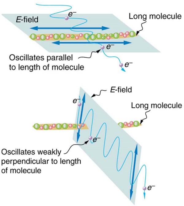
Figure 9. Long molecules are aligned perpendicular to the axis of a polarizing filter. The component of the electric field in an EM wave perpendicular to these molecules passes through the filter, while the component parallel to the molecules is absorbed.
Optical phenomena are often explained either in terms of quantum theory or wave mechanics, depending upon the particular problem that is being described. In considering the action of lenses, the wave-like properties can often be ignored and light is considered to travel in straight lines often termed rays. Simple ray diagrams are sufficient to explain many important aspects of microscopy including refraction, focal length, magnification, image formation, and diaphragms. In other instances, it is convenient to refer to light waves as being composed of discrete particles (quanta), especially when light is generated by quantum mechanical events or transformed into other forms of energy. This discussion will be restricted to optical lens models utilizing paraxial rays that conform to both the wave-like nature of light and to simple ray diagrams in which light travels from left to right. Paraxial light rays are those traveling very close to the optical axis, resulting in incident and refraction angles that are very small, which when measured in radians, can be considered as equal to their sine values.
Figure 7. A polarizing filter transmits only the component of the wave parallel to its axis, , reducing the intensity of any light not polarized parallel to its axis.
The Elliot Scientific MDE267 slide is an ultra-small, triple axis micropositioner with simple adjusters on an M4 tapped base for translation applications in ...
Figure 1. These two photographs of a river show the effect of a polarizing filter in reducing glare in light reflected from the surface of water. Part (b) of this Figure was taken with a polarizing filter and part (a) was not. As a result, the reflection of clouds and sky observed in part (a) is not observed in part (b). Polarizing sunglasses are particularly useful on snow and water. (credit: Amithshs, Wikimedia Commons)
Most objectives are corrected to work within a narrow range of image distances, and many are designed to work only in specifically corrected optical systems with matching eyepieces. The magnification inscribed on the objective barrel is defined for the tube length of the microscope for which the objective was designed.

While some of the microscope optical components act as image-forming elements, others serve to produce various modifications to illumination of the specimen and also have filtering or transforming functions. Components involved in formation of images by the microscope optical train are the collector lens (positioned within or near the illuminator), condenser, objective, eyepiece (or ocular), and the refractive elements of the human eye or the camera lens. Although some of these components are not typically thought of as imaging components, their imaging properties are paramount in determining the final quality of the microscope image.
Another interesting phenomenon associated with polarized light is the ability of some crystals to split an unpolarized beam of light into two. Such crystals are said to be birefringent (see Figure 15). Each of the separated rays has a specific polarization. One behaves normally and is called the ordinary ray, whereas the other does not obey Snell’s law and is called the extraordinary ray. Birefringent crystals can be used to produce polarized beams from unpolarized light. Some birefringent materials preferentially absorb one of the polarizations. These materials are called dichroic and can produce polarization by this preferential absorption. This is fundamentally how polarizing filters and other polarizers work. The interested reader is invited to further pursue the numerous properties of materials related to polarization.
Figure 10 illustrates how the component of the electric field parallel to the long molecules is absorbed. An electromagnetic wave is composed of oscillating electric and magnetic fields. The electric field is strong compared with the magnetic field and is more effective in exerting force on charges in the molecules. The most affected charged particles are the electrons in the molecules, since electron masses are small. If the electron is forced to oscillate, it can absorb energy from the EM wave. This reduces the fields in the wave and, hence, reduces its intensity. In long molecules, electrons can more easily oscillate parallel to the molecule than in the perpendicular direction. The electrons are bound to the molecule and are more restricted in their movement perpendicular to the molecule. Thus, the electrons can absorb EM waves that have a component of their electric field parallel to the molecule. The electrons are much less responsive to electric fields perpendicular to the molecule and will allow those fields to pass. Thus the axis of the polarizing filter is perpendicular to the length of the molecule.
Legendary Nikon optics in each Nikon upright microscope guarantee outstanding imaging results for clinical applications to multiphoton imaging.
Light reflected at these angles could be completely blocked by a good polarizing filter held with its axis vertical. Brewster’s angle for water and air are similar to those for glass and air, so that sunglasses are equally effective for light reflected from either water or glass under similar circumstances. Light not reflected is refracted into these media. So at an incident angle equal to Brewster’s angle, the refracted light will be slightly polarized vertically. It will not be completely polarized vertically, because only a small fraction of the incident light is reflected, and so a significant amount of horizontally polarized light is refracted.
In flat screen LCD televisions, there is a large light at the back of the TV. The light travels to the front screen through millions of tiny units called pixels (picture elements). One of these is shown in Figure 12 (a) and (b). Each unit has three cells, with red, blue, or green filters, each controlled independently. When the voltage across a liquid crystal is switched off, the liquid crystal passes the light through the particular filter. One can vary the picture contrast by varying the strength of the voltage applied to the liquid crystal.
Classical microscope design relies on two apertures and two diaphragms to control passage of light through the microscope. The field diaphragm, positioned in the lamphouse or in the base of the microscope, is an adjustable iris-type diaphragm that determines the size of the illuminating field of light. Positioned at the condenser front focal plane is the condenser aperture, another iris diaphragm that is utilized to adjust the beam size and angle of light rays striking the specimen. The third aperture has a fixed size and is located at the rear focal plane of the objective. This aperture determines the diameter of objective exit pupil and size of the intermediate image, while a conjugate fixed diaphragm in the eyepiece (the eyepiece field diaphragm) determines the size of the viewfield seen by the microscopist.
Many crystals and solutions rotate the plane of polarization of light passing through them. Such substances are said to be optically active. Examples include sugar water, insulin, and collagen (see Figure 13). In addition to depending on the type of substance, the amount and direction of rotation depends on a number of factors. Among these is the concentration of the substance, the distance the light travels through it, and the wavelength of light. Optical activity is due to the asymmetric shape of molecules in the substance, such as being helical. Measurements of the rotation of polarized light passing through substances can thus be used to measure concentrations, a standard technique for sugars. It can also give information on the shapes of molecules, such as proteins, and factors that affect their shapes, such as temperature and pH.
The definition of a microscope is an optical instrument used for viewing very small objects. These small objects can be anything from cells and microscopic life ...
Polaroid sunglasses are familiar to most of us. They have a special ability to cut the glare of light reflected from water or glass (see Figure 1). Polaroids have this ability because of a wave characteristic of light called polarization. What is polarization? How is it produced? What are some of its uses? The answers to these questions are related to the wave character of light.
The Sun and many other light sources produce waves that are randomly polarized (see Figure 4). Such light is said to be unpolarized because it is composed of many waves with all possible directions of polarization. Polaroid materials, invented by the founder of Polaroid Corporation, Edwin Land, act as a polarizing slit for light, allowing only polarization in one direction to pass through. Polarizing filters are composed of long molecules aligned in one direction. Thinking of the molecules as many slits, analogous to those for the oscillating ropes, we can understand why only light with a specific polarization can get through. The axis of a polarizing filter is the direction along which the filter passes the electric field of an EM wave (see Figure 5).
Function of arm inmicroscope
Image planes of the objective are presented in Figure 8, which illustrates a typical objective internal lens system, the specimen plane (Image Plane (2)), and the relative position of the microscope intermediate image (Image Plane (3)). The specimen plane is conjugate to the intermediate image plane, and each are separated from the objective principal planes by distances a and b, respectively. The objective front focal point is designated F', while the rear focal point, which occurs in the plane of the objective rear aperture, is noted as F. Internal lens elements are often complex assemblies consisting of hemispherical and meniscus lenses, lens doublets and triplets, and single lens elements of varying design.
Figure 8 illustrates what happens when unpolarized light is reflected from a surface. Vertically polarized light is preferentially refracted at the surface, so that the reflected light is left more horizontally polarized. The reasons for this phenomenon are beyond the scope of this text, but a convenient mnemonic for remembering this is to imagine the polarization direction to be like an arrow. Vertical polarization would be like an arrow perpendicular to the surface and would be more likely to stick and not be reflected. Horizontal polarization is like an arrow bouncing on its side and would be more likely to be reflected. Sunglasses with vertical axes would then block more reflected light than unpolarized light from other sources.
The eyepiece (or ocular) is designed to project either a real or virtual image, depending upon the complex relationship between the intermediate image plane, the eyepiece focal planes, and the internal eyepiece field diaphragm. In addition, the diameter of the fixed eyepiece diaphragm also determines the linear field size observed by the microscopist. This value is termed the field number or field of view number (abbreviated FN) and is often inscribed on the eyepiece housing exterior.
The general action of a perfect lens (or lens system) is to convert one spherical wave into another, with the geometrical properties of the lens determining the position of the focal point. As the distance of the light source from the lens is increased, the angle of diverging light rays entering the lens is decreased with a corresponding increase in the radius of the wavefront. If the radius of a spherical wave entering the lens is infinite, the radius of the spherical wave passing through the lens becomes equal to the focal length of the lens. A perfect lens has two focal points, and a plane wave passing through the lens is focused onto one of these points, depending upon whether the light rays enter from the left or right side of the lens.
Only the component of the EM wave parallel to the axis of a filter is passed. Let us call the angle between the direction of polarization and the axis of a filter θ. If the electric field has an amplitude E, then the transmitted part of the wave has an amplitude E cos θ (see Figure 7). Since the intensity of a wave is proportional to its amplitude squared, the intensity I of the transmitted wave is related to the incident wave by I = I0 cos2 θ, where I0 is the intensity of the polarized wave before passing through the filter. (The above equation is known as Malus’s law.)
Because S(1) and S(2) lie in conjugate planes, the image S(2) will be focused at S(1) by the lens. The focal length would then be represented by f' and the magnification (M) inverted to1/M due to the reduction in size of the image when the reverse situation is considered.
In summary, Ray paths through both finite tube length and infinity-corrected microscopes are reviewed and illustrated in Figures 12 and 13. A finite (fixed tube length) microscope optical train is illustrated inFigure 12, which includes the essential optical elements and ray traces defining the relationship between image planes. A specimen located a short distance before the objective front focal plane is imaged through conjugate planes onto the retina of the eye at Image Plane (4). The objective lens projects a real and inverted image of the magnified specimen into the intermediate image plane of the microscope (Image Plane (3)), which is located in the center of the eyepiece field diaphragm at a fixed distance behind the objective. In Figure 12, the objective rear focal plane is positioned at a location on the optical axis marked F'(Objective), and the distance between this focal plane and the intermediate image plane represents the optical tube length of the microscope.
where M(o) is the objective magnification and M(e) is the eyepiece lens magnification. If a projection lens is not utilized behind the eyepiece, but rather the eyepiece itself is employed to project the image onto the video image sensor or photographic emulsion, the total lateral magnification becomes:
Polarizing filters have a polarization axis that acts as a slit. This slit passes electromagnetic waves (often visible light) that have an electric field parallel to the axis. This is accomplished with long molecules aligned perpendicular to the axis as shown in Figure 9.
Image planes of the eyepiece, when utilized in projection mode, are presented in Figure 9. The principal focal points are F' and F, the front and rear focal points, respectively. The intermediate image plane (Image Plane (3)) is located in the center of the fixed eyepiece field diaphragm, which is placed either before or after the eyepiece field lens, depending upon the design. This image plane is conjugate to Image Plane (4) and is the location into which eyepiece focusing and measuring reticles are inserted. The length a represents the distance from the eyepiece fixed diaphragm to the principal plane of the eyelens (the lens closest to the observer's eye), while b is the distance from the eyelens to Image Plane (4), located on the sensor surface. Because a is greater than the front focal length of the eyelens (f'), the image formed at Image Plane (4) is a real (not virtual) image. The quantity f denotes the distance from the eyelens to the eyepiece rear focal plane (F), and also represents rear focal length of the eyepiece lens system.
Fundamental to the understanding of image formation in the microscope is the action of individual lens elements that comprise the components in the optical train. The simplest imaging element is a perfect lens (Figure 2), which is an ideally corrected glass element that is free of aberration and focuses light onto a single point. A parallel, paraxial beam of light passes through the converging lens and is focused, by refraction, into a point source located at the focal point of the lens (the point labeled Focus in Figure 2). Such lenses are often referred to as positive lenses because they induce a convergent light beam to converge more rapidly, or cause a divergent light beam to diverge less rapidly. A point source of light located at the lens focal point emerges as a paraxial, parallel beam of light as it leaves the lens, moving from right to left in Figure 2. The distance between the lens and the focal point is referred to as the focal length of the lens (denoted by the distance f in Figure 2).
Figure 8. Polarization by reflection. Unpolarized light has equal amounts of vertical and horizontal polarization. After interaction with a surface, the vertical components are preferentially absorbed or refracted, leaving the reflected light more horizontally polarized. This is akin to arrows striking on their sides bouncing off, whereas arrows striking on their tips go into the surface.
Objective lensmicroscopefunction
All of the imaging components in the optical microscope are governed by the basic geometrical relationships described above. This includes the collector lens, condenser, objective, eyepieces (in the projection mode), camera system, and the human eye.
An alternative method of representing a train of propagating light waves is illustrated in Figure 5 for an oblique light wave. This method relies on applying the laws of geometrical optics to determine the size and location of images formed by a lens or multi-lens system. Two representative light rays, one paraxial and one traveling through the center of the lens (the principal ray), are all that is necessary to establish the parameters of the imaging situation. Many textbooks on Gaussian optics refer to these light rays as characteristic rays, with the principal ray being the one that passes through the center of the entrance and exit pupils, the lens, and any aperture diaphragms present in the optical system. Often, the principal ray is omitted from consideration and the characteristic rays passing through the front and rear focal points of the lens are utilized to define the object and image size and location. In Figure 5, the second characteristic ray is illustrated as a yellow-filled dotted line passing through the front focal point (F') of the lens.
Function of stage inmicroscope
In the optical microscope, conjugate planes are imaged into each other and can collectively be observed while examining a specimen in the eyepieces. This concept is illustrated in Figure 14 with the image of a stained thin section of plant tissue superimposed on the iris leaves of the field diaphragm and a focusing reticle in the eyepiece intermediate image plane. The field iris diaphragm, adjacent to the lamp collector lens, is imaged sharply into the same plane as the specimen by the microscope condenser. Images of both the field diaphragm and the specimen are formed in the intermediate image plane by the objective and are projected into the fixed field diaphragm of the eyepiece, where the focusing reticle is located. Subsequently, the eyepiece (in conjunction with the observer's eye, located at Image Plane (4)) forms images of all three previous image planes on the sensor surface of an imaging system or the retina of a human eye. The field diaphragm, specimen, intermediate image, and retina all constitute a set of conjugate image planes that appear simultaneously in focus.
By now you can probably guess that Polaroid sunglasses cut the glare in reflected light because that light is polarized. You can check this for yourself by holding Polaroid sunglasses in front of you and rotating them while looking at light reflected from water or glass. As you rotate the sunglasses, you will notice the light gets bright and dim, but not completely black. This implies the reflected light is partially polarized and cannot be completely blocked by a polarizing filter.
Figure 3. The transverse oscillations in one rope are in a vertical plane, and those in the other rope are in a horizontal plane. The first is said to be vertically polarized, and the other is said to be horizontally polarized. Vertical slits pass vertically polarized waves and block horizontally polarized waves.
All we need to solve these problems are the indices of refraction. Air has n1 = 1.00, water has n2 = 1.333, and crown glass has n′2=1.520. The equation [latex]\tan\theta_{\text{b}}=\frac{n_2}{n_1}\\[/latex] can be directly applied to find θb in each case.
While you are undoubtedly aware of liquid crystal displays (LCDs) found in watches, calculators, computer screens, cellphones, flat screen televisions, and other myriad places, you may not be aware that they are based on polarization. Liquid crystals are so named because their molecules can be aligned even though they are in a liquid. Liquid crystals have the property that they can rotate the polarization of light passing through them by 90º. Furthermore, this property can be turned off by the application of a voltage, as illustrated in Figure 12. It is possible to manipulate this characteristic quickly and in small well-defined regions to create the contrast patterns we see in so many LCD devices.
For recording images with video microscopy, a photodiode array CCD camera, or classical photomicrography with film cameras, a specialized positive lens is often placed after the eyepiece (see Figure 10). Light rays leaving the eyepiece, which is focused to infinity, are converged by the positive lens onto the plane of the photocathode, CCD array, or photographic emulsion. When the magnification of the objective lens is neglected, the lateral magnification of the projection system (M(p)) is expressed as:
If you hold your Polaroid sunglasses in front of you and rotate them while looking at blue sky, you will see the sky get bright and dim. This is a clear indication that light scattered by air is partially polarized. Figure 11 helps illustrate how this happens. Since light is a transverse EM wave, it vibrates the electrons of air molecules perpendicular to the direction it is traveling. The electrons then radiate like small antennae. Since they are oscillating perpendicular to the direction of the light ray, they produce EM radiation that is polarized perpendicular to the direction of the ray. When viewing the light along a line perpendicular to the original ray, as in Figure 11, there can be no polarization in the scattered light parallel to the original ray, because that would require the original ray to be a longitudinal wave. Along other directions, a component of the other polarization can be projected along the line of sight, and the scattered light will only be partially polarized. Furthermore, multiple scattering can bring light to your eyes from other directions and can contain different polarizations.
A fairly large angle between the direction of polarization and the filter axis is needed to reduce the intensity to 10.0% of its original value. This seems reasonable based on experimenting with polarizing films. It is interesting that, at an angle of 45º, the intensity is reduced to 50% of its original value (as you will show in this section’s Problems & Exercises). Note that 71.6º is 18.4º from reducing the intensity to zero, and that at an angle of 18.4º the intensity is reduced to 90.0% of its original value (as you will also show in Problems & Exercises), giving evidence of symmetry.
Point S(1) on the lamp filament is conjugate to point S(2), which is imaged in the focal plane of the condenser aperture diaphragm when the microscope is configured to operate under conditions of Köhler illumination. The distance from S(1) to the first principal plane of the collector lens system is denoted by distance a, and the distance from the condenser iris diaphragm to the image-side principal plane of the collector is given by distance b. The microscope field diaphragm (Figures 6 and 7) governs the diameter of the light beam emitted by the illumination system before it enters the condenser aperture.
by V Averchenko · 2024 — Abstract page for arXiv paper 2407.18826: Effect of group-velocity dispersion on the generation of multimode pulsed squeezed light in a ...
Figure 2. An EM wave, such as light, is a transverse wave. The electric and magnetic fields are perpendicular to the direction of propagation.
Most microscopes provide a translation mechanism attached to the stage that allows the microscopist to accurately position, orient, and focus the specimen to optimize visualization and recording of images. The intensity of illumination and orientation of light pathways throughout the microscope can be controlled with strategically placed diaphragms, mirrors, prisms, beam splitters, and other optical elements to achieve the desired degree of brightness and contrast in the specimen.
Function ofmicroscope
The relationship between conjugate image planes in the condenser lens and the illumination system are illustrated in Figure 7. The field diaphragm (Image Plane (1)) is imaged in the same plane as the specimen (Image Plane (2)) when the microscope is configured for Köhler illumination. The front focal plane of the condenser (F') resides in the center of the aperture diaphragm. Lengths a and b represent the respective distances of the field diaphragm (Image Plane (1)) and the specimen plane (Image Plane (2)) from the principal planes of the condenser lens elements. Light emitted by the lamphouse and passing through the condenser is formed into a cone of illumination that bathes and subsequently passes through the specimen. Adjustment of the condenser aperture iris diaphragm opening size controls the numerical aperture of this illumination cone.
Figure 4. The slender arrow represents a ray of unpolarized light. The bold arrows represent the direction of polarization of the individual waves composing the ray. Since the light is unpolarized, the arrows point in all directions.
Another set of points utilized to define lens parameters are the nodal points, which occur where the extensions of oblique light rays passing through the lens intersect the optical axis. Nodal points are not illustrated in Figure 5 , but would lie very close to the principal points of the lens. Thus, three pairs of points, the lens focal points (F and F'), principal planes (P(1)and P(2)), and the principal nodes all lie on the lens optical axis. If the location of the focal points and either the principal points or the nodal points is known, then geometrical construction of ray traces to elucidate object and image parameters can be undertaken without considering refraction of light rays at each surface of the lens. The result is that any lens system can be simulated utilizing only the focal points and principal planes by drawing ray traces as if they encounter the first principal plane, travel parallel to the optical axis, and emerge from the second principal plane without refraction.
Presented in Figure 1 is a Nikon Eclipse E600 microscope equipped with a trinocular head and DXM-1200 digital camera system for recording images. Illumination is provided by a tungsten-halide lamp positioned in the lamphouse, which emits light that first passes through a collector lens and then into an optical pathway in the microscope base. Also stationed in the microscope base is a series of filters that condition the light emitted by the incandescent lamp before it is reflected by a mirror and passed through the field diaphragm and into the substage condenser. The condenser forms a cone of illumination that bathes the specimen, located on the microscope stage, and subsequently enters the objective. Light leaving the objective is diverted by a beam splitter/prism combination either into the eyepieces to form a virtual image, or straight through to the projection lens mounted in the trinocular extension tube, where it can then form an image on the CCD photodiode array positioned within the digital imaging system.
In a parallel beam of light, individual monochromatic light waves form a wavetrain having a combination of electric and magnetic vectors vibrating in phase to form a wavefront, which has a vibration orientation perpendicular to the direction of wave propagation. The plane wave is converted to a spherical wave as it passes through the perfect lens, with the front centered at the focal point (Focus) of the lens (Figure 2). Light waves arrive at the focal point in phase and interfere constructively with each other at this location. Alternatively, light comprising a spherical wavefront emanating from the focal point of a perfect lens is converted by the lens into a plane wave (proceeding from right to left in Figure 2). Each light ray in the plane wave undergoes a different change of direction upon encountering the lens because it arrives at the surface in a slightly different angle of incidence. Upon emerging from the lens, the direction of the light ray also changes. In real systems, the angle of refraction and focal point of a lens or group of lenses is dependent upon the thickness, geometry, refractive index, and dispersion of each component in the system.
Brewster’s angle: [latex]{\theta }_{\text{b}}={\tan}^{-1}\left(\frac{{n}_{2}}{{n}_{1}}\right)\\[/latex], where n2 is the index of refraction of the medium from which the light is reflected and n1 is the index of refraction of the medium in which the reflected light travels
Figure 10. Artist’s conception of an electron in a long molecule oscillating parallel to the molecule. The oscillation of the electron absorbs energy and reduces the intensity of the component of the EM wave that is parallel to the molecule.
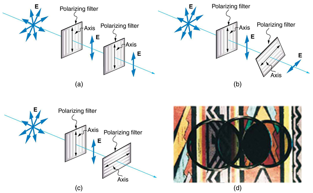
Figure 6 shows the effect of two polarizing filters on originally unpolarized light. The first filter polarizes the light along its axis. When the axes of the first and second filters are aligned (parallel), then all of the polarized light passed by the first filter is also passed by the second. If the second polarizing filter is rotated, only the component of the light parallel to the second filter’s axis is passed. When the axes are perpendicular, no light is passed by the second.
The optical components contained within modern microscopes are mounted on a stable, ergonomically designed base that allows rapid exchange, precision centering, and careful alignment between those assemblies that are optically interdependent. Together, the optical and mechanical components of the microscope, including the mounted specimen on a glass micro slide and coverslip, form an optical train with a central axis that traverses the microscope base and stand. The microscope optical train typically consists of an illuminator (including the light source and collector lens), a substage condenser, specimen, objective, eyepiece, and detector, which is either some form of camera or the observer's eye (Table 1). Research-level microscopes also contain one of several light-conditioning devices that are often positioned between the illuminator and condenser, and a complementary detector or filtering device that is inserted between the objective and the eyepiece or camera. The conditioning device(s) and detector work together to modify image contrast as a function of spatial frequency, phase, polarization, absorption, fluorescence, off-axis illumination, and/or other properties of the specimen and illumination technique. Even without the addition of specific devices to condition illumination and filter image-forming waves, some degree of natural filtering occurs with even the most basic microscope configuration.
Figure 6. The effect of rotating two polarizing filters, where the first polarizes the light. (a) All of the polarized light is passed by the second polarizing filter, because its axis is parallel to the first. (b) As the second is rotated, only part of the light is passed. (c) When the second is perpendicular to the first, no light is passed. (d) In this photograph, a polarizing filter is placed above two others. Its axis is perpendicular to the filter on the right (dark area) and parallel to the filter on the left (lighter area). (credit: P.P. Urone)
The height of image S(2) is denoted by the quantity h(2), and represents an increase in size, resulting from magnification of the object or specimen S(1) positioned at the front of the lens and having a height of h(1). The lateral magnification, M of this simple lens (which approximates a Gaussian thin lens) is expressed by the equation:
Microscopeparts diagram
Older finite, or fixed tube length, microscopes have a specified distance from the nosepiece opening, where the objective barrel is secured, to the ocular seat in the eyepiece tubes. This distance is referred to as the mechanical tube length of the microscope. The design assumes that when the specimen is placed in focus, it is a few microns further away than the front focal plane of the objective. Finite tube lengths were standardized at 160 millimeters during the nineteenth century by the Royal Microscopical Society (RMS) and enjoyed widespread acceptance for over 100 years. Objectives designed to be used with a microscope having a tube length of 160 millimeters are inscribed with this value on the barrel.
If the point S(1) in Figure 4 is expanded into a series of points spread throughout the same focal plane, then a perfect lens will focus each point in the series onto a conjugate point in the focal plane of S(2). In the case where a point set of S(1) lies in a plane perpendicular to the optical axis of the lens, then the corresponding conjugate points in set S(2) would also lie in a plane that is perpendicular to the axis. The reverse is also true: the lens will focus every point in the set S(2) onto a conjugate point on the plane or surface of point set S(1). Corresponding planes or surfaces of this type are known as conjugate planes.
Polarization is defined in terms of the pattern traced out in the transverse plane by the electric field vector as a function of time. Light is called natural ...
Several of the principal image planes in the microscope occur either in fixed or adjustable apertures or diaphragms, which are essential components of all optical systems. A diaphragm, also referred to as a stop, is an opaque gate or a lens mount with a circular opening (often adjustable) that controls light flow through the microscope. Two basic types of diaphragms are utilized in the microscope: the aperture diaphragm, which adjusts the aperture angles in the microscope, and the field diaphragm that controls the size of the field imaged by the instrument. The primary role of diaphragms in the optical microscope is to prevent light rays with severe aberration and stray light from reaching the image planes, and to ensure a suitable distribution and intensity of light in both the object and image space.
What angle is needed between the direction of polarized light and the axis of a polarizing filter to reduce its intensity by 90.0%?
Magnification of the intermediate image with infinity-corrected optical microscope systems is determined by the ratio of the focal lengths of the tube lens and objective lens. Because the focal length of the tube lens varies between 160 and 250 millimeters (depending upon the manufacturer and model), the focal length of the objective can no longer be assumed to be 160 millimeters divided by its magnification. Thus, an objective having a focal length of 8 millimeters in an infinity-correct microscope with a tube lens focal length of 200 millimeters would have a lateral magnification of 25x (200/8).
Magnifications inscribed on the objective barrel or eyepiece rim by the manufacturer are nominal and must be calibrated with a stage micrometer to obtain the exact value. Measurements of magnification are accomplished by placing the stage micrometer in the specimen plane (on the microscope stage) and imaging the finely ruled lines under identical optical conditions.
Light is one type of electromagnetic (EM) wave. As noted earlier, EM waves are transverse waves consisting of varying electric and magnetic fields that oscillate perpendicular to the direction of propagation (see Figure 2). There are specific directions for the oscillations of the electric and magnetic fields. Polarization is the attribute that a wave’s oscillations have a definite direction relative to the direction of propagation of the wave. (This is not the same type of polarization as that discussed for the separation of charges.) Waves having such a direction are said to be polarized. For an EM wave, we define the direction of polarization to be the direction parallel to the electric field. Thus we can think of the electric field arrows as showing the direction of polarization, as in Figure 2.
Hex and Torx keys and also known as Allen Keys are essential to any toolbox, get yours today at Gregg Distributors. Browse from industry-leading brands like ...
polarization: the attribute that wave oscillations have a definite direction relative to the direction of propagation of the wave
Figure 14. Optical stress analysis of a plastic lens placed between crossed polarizers. (credit: Infopro, Wikimedia Commons)
Find Polaroid sunglasses and rotate one while holding the other still and look at different surfaces and objects. Explain your observations. What is the difference in angle from when you see a maximum intensity to when you see a minimum intensity? Find a reflective glass surface and do the same. At what angle does the glass need to be oriented to give minimum glare?
Figure 13. Optical activity is the ability of some substances to rotate the plane of polarization of light passing through them. The rotation is detected with a polarizing filter or analyzer.


 Ms.Cici
 8618319014500