
Diffraction-limited ultrabroadband terahertz spectroscopy - diffraction limited system
The evaluation length is a necessary segment of the profile used to assess surface roughness and may consist of one or several sampling lengths. Since surface roughness may not be uniformly distributed on different parts of the component’s surface, a single sampling length may not adequately represent a specific surface roughness feature. Therefore, multiple sampling lengths are taken from the surface to evaluate the surface roughness. Typically, the evaluation length includes five sampling lengths.
A: The arithmetic mean centerline is a line within the sampling length that divides the actual profile into upper and lower portions and ensures that the areas above and below the centerline are equal.
A: It is a segment of baseline length used to identify surface roughness characteristics. The larger the surface roughness, the greater the required sampling length. Specifying the sampling length aims to limit and mitigate the influence of other geometric errors on the measurement results of surface roughness. Within the sampling length, there should be five or more peaks and valleys of the profile. The sampling length values are selected in GB/T 1031-1995: Surface roughness – Parameters and their values.
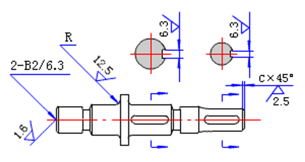
7) When most of the surface requirements of the parts are the same, they shall be uniformly marked in the upper right corner, and the word “rest” shall be added. To simplify the labeling, or when the position is limited, the simplified codes can be marked, and the method of omitting notes can also be used. Still, the meaning of these simplified codes (symbols) must be explained near the title column. When unified and simplified marking is adopted, the code and text description shall be 1.4 times the code and text marked on other surfaces on the graph. As shown in Figure 8.
Solid Fiber Optic Ribbon: I first saw these as the light in the inside of illuminated ankle bracelets for biking, and later in a pair of costume suspenders I found a Michael's crafts. As you can see in the second photo, these fibers are basically just like other large end glow fibers in a slightly different shape. Their glow seems to appear more visible when they are encased inside fabric or another diffusing material like they are in the suspender s in the third photo above. I am not even sure if these ribbons are technically fiber optics or just another plastic material that transmits light fairly well, but I think they have a lot of potential for interesting uses.
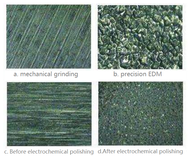
A: The basic symbol with a short dash represents the surface obtained using material removal methods. For example: turning, milling, drilling, grinding, shearing, polishing, etching, EDM (Electric Discharge Machining), oxy-fuel cutting, etc.
Bestfiber optic lighted
Rsm: Mean Spacing of the Profile Elements – It represents the average width of profile micro-roughness elements within the sampling length. The micro-roughness spacing refers to a profile segment that includes a peak and its adjacent valley along the centerline. Even with the same Ra value, the Rsm value may vary, reflecting different textures. Surface evaluations emphasizing texture often focus on both Ra and Rsm as key indicators.
Multi Strand End Glow Cable: this is a collection of end glow fibers bundled inside a plastic casing. I have seen these with thick black casings designed to block all light except at the ends of the fibers, or in clear casings which allow you see the fibers all the way along the cable. Usually these cables are filled with fibers of all the same diameter, but I have also seen cables like these that contain a few slightly different sized fibers for variety (they are designed for making star effect ceilings). Buying fiber optics in this form can be useful especially if you are planning to use the fiber in bundles and you want to make sure all your fibers curve in the same direction. Taking the fibers out of the casing can be a little tricky however, and often results in nicking the fibers in places.
Solid Core End Glow (not pictured): These are single strands up to 14mm in diameter encased in black PVC casing. I haven't actually used these, but they seem to be more like a side glow fiber that is encased so that light will only emerge from the end. They are mostly used in displays and water features to channel light to specific points. They could potentially be useful in wearables for a similar purpose.
Another important consideration for wearable fiber optic projects is, how to attach the fibers to the garment or accessory you are making. Depending on how many separate fibers or bundles of fiber you are working with, this can be a time consuming process, and I'm always looking for new ways to solve this problem.
tau; inf; nan. Previous topic. numbers — Numeric ... π = 3.141592… e. e = 2.718281… tau. τ = 2π ... On some non-Windows builds, the underlying C library ...
Fiber opticlighting for homes
A: The surface shape is characterized by micro-discrimination of the direction of the machining traces, applied to medium-sized machine tools (improved precision) sliding guideway surfaces, working surfaces of sliding bearings, main surfaces of fixture positioning elements and drill sleeves, working journals of crankshafts and camshafts, indexing The surface of the disc, the working surface of the journal and the bushing under high-speed work, etc.
You can combat this dimming by putting a light source at both ends of the fiber as I've done in the third photo above. This can also create amazing blended color effects by having different colored LEDs at each end of the fiber. Even putting a small mirror, instead of a second LED, at the other end of the fiber helps keep the light contained, making the whole strand brighter.
Contact stiffness is the ability of mating surfaces to resist deformation under external forces. The overall stiffness of a machine largely depends on the contact stiffness between its components.
The rougher the surface, the smaller the effective contact area between mating surfaces, leading to higher pressure and increased friction resistance, resulting in faster wear.
Another, even easier way to access some great lighting programs, is to buy a pre-programmed chip like the Cool Neon Driver I used in my LED skirt project and wire that to addressable LEDs. This will give you many different lighting patterns to choose from and can be controlled by a remote.
A: On the same component, the surface roughness value of the working surface should be smaller than that of the non-working surface. The surface roughness value of friction surfaces should be smaller than that of non-friction surfaces. The surface roughness value for surfaces experiencing rolling friction should be smaller than that of sliding friction surfaces. Surfaces with higher motion speed and higher unit pressure should have smaller surface roughness values. Surface roughness values should be selected smaller for surfaces subjected to cyclic loads or susceptible to stress concentration, such as fillets and grooves. High-precision mating surfaces, surfaces with small clearances in mating fits, and surfaces requiring reliable connections and subjected to heavy loads should have smaller surface roughness values. For mating surfaces with similar requirements, the smaller the component size, the smaller the surface roughness value should be. For the same accuracy grade, the surface roughness value of small-sized components should be smaller than that of large-sized components, or, specifically, shafts should have smaller surface roughness values than holes. For mating surfaces, their dimensional tolerances, form tolerances, and surface roughness should be coordinated, and there is generally a specific corresponding relationship between them.
Jun 24, 2022 — CNC milling, CNC turning, or multi-axis CNC machining can create stress or exert pressure on existing internal stress in any plastic, especially ...
A: The surface shape is characterized by visible machining traces. It is applied to semi-rough machining surfaces, non-contact-free surfaces such as brackets, boxes, clutches, pulley sides, and cam sides, surfaces in contact with bolt heads and rivet heads, and all shafts and holes. Undercut groove, joint surface of the general shutter, etc.
The parts are the piston pump connecting the rod hole, cylinder barrel, slide valve bushing, plunger, and piston, and Ra is 0.8~0.4μm.
A: The surface shape is characterized by obvious tool marks, which are rarely used when applied to rough processing surfaces. Casting, forging, and gas-cutting blanks can meet this requirement.
5) When local heat treatment or partial coating needs to be indicated, the range shall be drawn with a thick dotted line and the corresponding size shall be marked, and the requirements may also be written in the surface roughness symbol. As shown in Figure 6.
Another way I like to integrate fibers into my designs, especially the larger side light fibers, is by sewing channels into two layers of sheer fabric and inserting the fibers into these channels, almost like creating my own large scale fiber optic fabric (see photos 2 and 3). This is a slightly less time consuming way to contain the fibers, and it creates a nice effect by making the fibers appear to be hovering in midair when it's dark.
Ra: Arithmetic Mean Deviation of the Profile – It represents the arithmetic average of the absolute values of profile deviations within a sampling length (lr). In practical measurements, more measuring points result in a more accurate Ra value.
You can also buy pre-made products that are designed to light fiber optics. Natalina made her dress and coat using a fiber optic whip that comes pre-assembled with a large bundle of fibers attached to a bright RGB LED with many pre-loaded programs. In many ways these whips are great products, but the battery life is not as good as it should be and the shape and size of the whip is not particularly well suited to wearables.
Fiber Opticsensory lights
With over 14 years of experience, Beyond gears support the further success of OEM clients with cost-effective manufacturing, processes, and premium service.
Before attaching the fibers to your light source, you also have to be sure that the end of your fibers are cut cleanly to allow the maximum amount of light to penetrate.
A: Rz is the average of the five largest peak heights and the five largest valley depths within the sampling length. A higher Rz value indicates a rougher surface. Rz provides an excellent visual representation for evaluating the height parameter of surface roughness and can be easily measured using optical instruments. However, it has limitations in reflecting the geometric characteristics of the measured profile.
I haven't experimented that much with manipulating the form of the actual fibers themselves, but there are a few possibilities here that could have some very interesting results.
1)The surface roughness code (symbol) shall be marked on the visible contour line, dimension line, dimension extension line or their extensions. The tip of the symbol must point from outside the material to the surface. As shown in Figure 2.
Because of the way they are constructed, with a cladding that is intentionally less effective, light gradually escapes along the whole length of the fiber creating a fairly even glow almost like a neon tube or el wire.
For clearance fits, rough surfaces are more prone to wear, causing the clearance to increase gradually during operation. For interference fits, the micro-peaks on the surfaces are flattened during assembly, reducing the actual effective interference and weakening the connection strength.
Fiber optics can be used to bring illumination to many kinds of projects, but for this Instructable I'm going to focus on their use in wearables, because that's my area of expertise. Fiber optics are also especially great for clothing, costumes and accessories because they allow you to distribute light from a single source, therefore making your project require fewer lights and less power (always an important consideration when designing wearables). Because the fibers can carry light far from the electronics that are the source of illumination, they are also great for projects that need to be weather-proof or washable.
If you are using LED strip to light your fibers, connecting them gets a bit trickier because the LEDs have such a low profile, there isn't much to connect to. Everyone I know who works with fiber optics seems to have come up with their own solution to this problem.
A: The choice of surface roughness must not only meet the functional requirements of the surface of the part but also consider the economy of processing.
A: The surface shape is characterized by a mirror-like glossy surface, which is applied to the surface of the raceway, ball, and roller of the particularly precise rolling bearing ring, the mating surface of the plunger and the plunger sleeve in the high-pressure oil pump, and ensures a highly airtight bonding surface, etc.
Bulk fiber optics are still not widely available as a retail product, but they are not hard to find if you know where to look. If you are planning a project that uses fiber optics, I recommend starting to gather your materials a few weeks ahead of time because the best sources are often overseas. Make sure you read the rest of this Instructable before you dive into ordering so you understand exactly which fiber optic product you are looking for.
A: The surface shape is characterized by a foggy mirror surface, which is applied to the measuring surface of the instrument, the working surface of the high-precision clearance fit parts in the measuring instrument, the working surface of the gauge block with a size exceeding 100mm, etc.
End emitting fibers are great for directing individual points of light far from a single light source. Projects like the Star Map in the second photo above make use of the ends of the fibers to spread the light from just a few points of illumination into a myriad of tiny stars.
Side emitting fibers (also called side glow, or side light) are usually larger and more flexible than end emitting fibers. They seem to be available anywhere from 2mm to 12mm in diameter.
I've already talked about a lot of my favorite fiber optic projects, but here's a longer list of great inspiration that will show you some of the beautiful things you can create with fiber optic lighting.
For my Fiber Optic Fairy Wings, I used a much simpler, and slightly jankier, method. I bundled my end glow fibers into groups of about 30, then heat shrunk the ends together and cut them with an exacto knife to create a smooth edge. I installed my LED strip inside a small box with holes drilled in the sides, then fed my fiber optic bundles through the holes and hot glued them into place up against the LEDs, being careful not to get any hot glue between the ends of the fibers and the LEDs as that would block light from illuminating the fibers (last photo).
A: The surface shape feature is that the processing traces cannot be seen clearly. It is applied to the surface with high surface quality requirements, the working surface of medium-sized machine tools (regular precision), the joint surface of the spindle box and cover surface of combined machine tools, and the working surface of medium-sized flat pulleys and V-belt pulleys, The press-in hole of the bushing sliding bearing, generally the journal of low-speed rotation—non-matching surfaces of some important parts of aviation and aerospace products.
Surface roughness is measured using a stylus profilometer, where a diamond-tipped stylus with a radius of curvature of about 2 micrometers glides slowly along the surface to be measured. The vertical displacement of the diamond stylus is converted into an electrical signal by an inductive length sensor. After amplification, filtering, and calculations, the surface roughness value is indicated on a display instrument. Additionally, the measured profile curve of the cross-section can be recorded using a recording device. Instruments capable of displaying only the surface roughness value are referred to as surface roughness testers, while those capable of recording the surface profile curve are called surface roughness profilometers. Both types of measurement tools have electronic calculation circuits or electronic computers that can automatically calculate parameters such as arithmetic mean deviation (Ra), ten-point height of micro-roughness (Rz), maximum height of the profile (Ry), and other evaluation parameters. These measurement tools offer high efficiency and are suitable for measuring surface roughness with Ra ranging from 0.025 to 6.3 micrometers.
This method is suitable for on-site measurements in workshops and is commonly used for measuring surfaces with medium to rough roughness. The process involves comparing the surface to be measured with a roughness specimen with known numerical values to determine the roughness value of the measured surface.
The most basic way to attach fibers directly to a garment is hand sewing. This is how I attached the fibers to my fairy wings in the first photo. Hand sewing down bundles of fiber optics is pretty time consuming and it takes a bit of skill to make it look neat, but it does work well, and it gives you a lot of room to create freehand layouts. I usually use a thin fishing line or clear thread to sew down the fibers, which ends up being almost invisible against the fibers.
2) Center hole working surfaces, keyway working surfaces, and chamfered, rounded surfaces for simplified labeling. As shown in Figure 3.
Rmr: Rmr is a shape feature parameter that represents the ratio of the profile supporting length, obtained by intersecting the profile with straight lines parallel to the centerline and at a distance c from the profile’s highest peak within the sampling length, to the sampling length itself.
If you only want to see see the points of light at the the ends of the fibers, you can hide most of the fiber inside a garment (like NLED-Projects did with this Fiber Optic Top Hat) and just attach the strands so the ends are visible as shown in the last photo above.
The reference line is the midline for evaluating surface roughness parameters. There are two types of reference lines: the least squares centerline and the arithmetic mean centerline. In the least squares centerline, the sum of squared deviations of points on the profile within the sampling length is minimized, representing the geometric contour shape. The arithmetic mean centerline is the one where the area above and below the centerline within the sampling length is equal. Theoretically, the least squares centerline is the ideal reference line, but it is challenging to obtain in practical applications. Therefore, the arithmetic mean centerline is commonly used as a replacement, and a straight line with a close approximation of the position can be used for measurement.
The sampling length is a specified segment of the baseline used to assess surface roughness. It should be chosen based on the component’s actual surface formation and texture characteristics, reflecting the surface roughness features. When determining the sampling length, we should consider the overall direction of the actual surface profile. Specifying and selecting the sampling length aim to limit and mitigate the influence of surface waviness and form errors on the measurement results of surface roughness.
Fiber OpticLight strands
Jan 13, 2022 — In photography, ND filters can help you slow down motion in bright conditions for shooting long exposure photography. Think a smooth flowing ...
Dec 12, 2014 — When this video started circulating online earlier this month, it was widely reported that this practice had something to do with improving ...
A: The surface shape feature is that the direction of the processing marks can be distinguished. It is applied to the surface of the sliding guideway of medium-sized machine tools (ordinary precision), the guide rail pressure plate, the surface of cylindrical pins and conical pins, the dial of general precision, the outer surface that needs to be chrome-plated and polished, and rotates at a medium speed. The journal, the positioning pin is pressed into the hole, etc. It is a commonly used value for mating surfaces, important mating places for medium and heavy equipment, and economical for grinding.
These fibers only seem to conduct light a few feet down their length before it fades and yellows, but they have an interesting look and could be great for certain projects.
3) Marking method when tooth (tooth) shape is not drawn on the working surface of gear, involute spline, thread, etc. As shown in Figure 4.
End emitting fibers do leak a little light along the strands however, and when gathered into bunches, this light becomes visible in the dark, as you can see in projects like Natalina's Fiber Optic Dress and Coat and my Fiber Optic Fairy Wings above. You can also strategically nick or abrade the fibers to create points of light along their lengths. (I'll talk more about this later).
The surface roughness of a component’s measured surface and the measuring tool directly affects measurement accuracy, especially in precision measurements.
A: Surface roughness significantly influences friction, wear, fatigue strength, corrosion resistance, and the fit properties between components.
The clear inner core allows light to travel unimpeded down the length of the fiber while the cladding acts like a one-way mirror, containing any light that tries to escape the fiber by bouncing it back into the core in a process called total internal reflection. This combination of core and cladding allows light to travel along the fiber for great distances, even around curves, emerging at the other end nearly as bright as the original source of illumination.
A: The surface shape is characterized by the direction of indistinguishable machining traces, which is applied to the taper hole of the spindle of the precision machine tool and the conical surface of the tip; the joint surface of the precision spindle and the rotating shaft with a small diameter, the piston pin hole of the piston, and the airtight surface and supporting surface are required. The leaf pot and the back of the blade of the aero-engine.
A: The surface of a component formed through cutting processes or other methods always contains geometric errors due to material plastic deformation, mechanical vibrations, friction, and other factors during the manufacturing process.
A: The surface shape is characterized by a mirror surface, which is applied to the working surface of the gauge block, the measuring surface of the high-precision measuring instrument, and the metal mirror surface of the optical measuring instrument.
Ashley Newton, who first introduced me to side emitting fiber optics, and worked with me to create my Sea Warrior outfit, has a very effective method that involves 3D printing a piece that holds the LED strip and has nodes with holes that the fiber optics plug into above each pixel (see photos 2 and 3 above). Variations on this shape can be 3D modeled to fit the form of what you are creating. I talk more about this method in my Fiber Optic Sea Warrior Instructable.
Fiber optics! Fiber optics! Admittedly, I'm a little obsessed with fiber optics, and for good reason. They are a durable, versatile, and relatively simple way to add beautiful lighting effects to anything you're making. Just look at some of the gorgeous projects you can create with them! There was a time when I mostly used el wire in my illuminated designs, but ever since the amazing Natalina and Technorainbows introduced me to the wonders of fiber optics in their various forms, I've been on a bit of a fiber optic bender. So come fall down this rabbit hole with me, and turn yourself into a mesmerizing bioluminescent sea creature... you know you want to.
The possibilities for lighting fiber optics range from simple to extremely complex, and can make a huge difference to the look of your project. When you are choosing lighting, keep in mind that the brighter your light is, the more visible your fiber optic illumination will be. Also, from a personal aesthetic perspective, I think staying away from out-of-the-box primary LED colors like green, blue and red, helps keep a fiber optic project from looking like a cheesy Christmas decoration. I usually go for blended or de-saturated colors for a more subtle and beautiful effect.
Rough surfaces on components contain larger valleys that act as stress concentrators, similar to sharp notches and cracks, which significantly affect the fatigue strength of the parts.
On designs like the Sea Warrior headpiece, the 3D printed nodes that marry the fibers to the lights also function as a means of attaching the fibers to the headpiece (photo 5). Because they are only a few inches long, they can plug into the nodes at the base and then fan out freely.
Fiber OpticCurtain
One of the most important things to think about when you are planning a fiber optic project is, "how am I going to attach my fibers to my lights?" It's crucial create a clean strong connection between your light source and the ends of your fibers so that light shines directly into the fibers and makes them glow as brightly as possible. A big challenge in this is the fact that the fiber optics themselves are quite slippery and don't adhere to most glues very effectively. I have found that superglue and some epoxies seem to stick the best, but you have to be careful not to get superglue on the end of the fibers where is can cause clouding that effects light transmission down the strand.
A: It affects the reliability and stability of the mating performance. Initial wear will quickly remove the peaks for clearance fit, resulting in increased clearance. During assembly, the peaks will be flattened for an interference fit, reducing the actual effective interference, especially for small-size fits. Therefore, mating surfaces requiring high stability, small clearance for dynamic fits, and firm and reliable connection for static fits should have lower Ra values. For the same tolerance grade, smaller-sized components should have lower Ra values compared to larger-sized ones, especially for 1~3 grade tolerance, and the Ra value should be smaller for shafts compared to holes with the same tolerance grade. Additionally, for components with the same mating properties, smaller-sized parts tend to have smaller Ra values.
As I mentioned in the previous step, standard 5mm diffused LEDs are fairly easy to attach to fiber optics because you can slip a heat shrink tube over both the LED and the fiber optic bundle, shrink it down, add a little glue and you have a fairly strong connection between the two (see first photo). You can buy RGB addressable LEDs in this form from places like Adafruit, so you don't need to sacrifice programability. This Instructable also shows how to achieve a similar connection using Sugru instead of heat shrink.
A: The least squares centerline is a line within the sampling length that minimizes the sum of squared profile deviations at each point on the profile.
End emitting fibers (also called end glow, or end light) are the classic fiber optics, with bright points of light at the ends and very little light escaping along the strands themselves. They are usually thin, somewhere from .25 to 3mm in diameter. They are also generally stiffer than the side emitting fibers.
This worked fairly well, though some fibers in the middle of the bundles were still loose after I had glued them in. Since I was going to be sewing all my fibers down very securely anyway, this didn't really matter, but I would like to find even better ways make sure all the fibers are secure.
The fibers being used in these textiles are end glow fibers that have been strategically abraded to release light along the length of the strands, and the resulting fabric is fairly stiff and coarse. The fibers are usually woven in one direction (warp or weft only) and they need to be bundled and connected to a light source at one end. This greatly limits how the fabric can be cut if you want to retain glow in all the fibers, which means you can only use the fabric in garments with certain kinds of pattern shapes. All this can be worked around, but it is certainly not the easiest material to deal with.
Due to variations in machining methods and workpiece materials, the depth, density, shape, and texture of the resulting surface roughness differ.
Fill your space with an aromatherapeutic super fine mist by just adding a few drops of your favorite essential oil to the diffuser. The microchip vibrates at ...
A: Industry Standards: Different industries have specific standards and guidelines for evaluating surface roughness. For example, ISO 1302 and ISO 4287 are commonly used international standards that define surface texture parameters and evaluation methods.
Personally, I also find the aesthetic of the fabric itself to be a little tacky if it isn't used right. I have seen it illuminated with moving lasers, or programmable lights in ways that give it a more dynamic, subtle look. Strategically abrading the fibers to add patterns of light to the fabric can also create beautiful results. I haven't played with this material much myself, but it is definitely an interesting possibility for wearable projects, and I'm sure it will continue to be developed in new and exciting ways.
A: The surface shape is characterized by slight processing traces, and it is applied to semi-finishing surfaces, surfaces such as boxes, brackets, covers, sleeves, etc., that are connected to other parts without matching requirements, surfaces that require bluing, and pre-processing that require knurling surface, all outer surfaces where the spindle does not contact, etc. It is the surface roughness value achieved economically by basic cutting methods such as turning.
To take full advantage of the dynamic lighting possibilities of fiber optics, however, you really need programable lighting, or at least a light source that has been pre-programmed.
While attempting to straighten some fibers for a project, I accidentally melted some with an iron causing them to curl up in odd ways. I thought this actually looked pretty interesting a little like a Chihouly sculpture or a sea creature. It also made the fibers glow brighter
6) The continuous surface of the part and the surface of repeated elements (holes, grooves, teeth, etc.) and a discontinuous surface connected by a thin solid line, the code (symbol) is marked only once. As shown in Figure 7.
Shop Canned Air online at AceHardware.com and get Free Store Pickup at your neighborhood Ace.
Fiber OpticLights for Ceiling
White Core Side Glow Fiber, or Light Pipe: These are similarly flexible to the clear "solid core" side glow fibers, but have a white core embedded in the center of a clear strand. The white core illuminates and radiates light into the clear section, making this fiber look much more like el wire as you can se in the first photo.
Surface roughness refers to the irregularities on a processed surface characterized by small spacing and tiny peaks and valleys. The distance between two consecutive peaks or valleys (wavelength) is very small (below 1 mm), representing micro-scale geometric errors. Specifically, it refers to the small peaks and valleys’ Z-height and spacing S condition. Generally, it is categorized based on S as follows:
Jenn Mann who also makes amazing fiber optic wearables, has found a way to use layers of laser cut acrylic to create a similarly shaped connecting strip between LEDs and fibers.
A: The surface shape is characterized by a bright glossy surface, which is applied to the raceway of the rolling bearing ring, the surface of the ball and the roller, the working surface of the medium-precision clearance fit parts in the measuring instrument, the measuring surface of the working gauge, etc.
Using sandpaper on fiber optic fabric creates patterns of brighter glow in different areas. With the right kind of masking and strategic abrading, I think this technique has a lot of potential to make fiber optic fabric more exciting. Of course you have to be careful not to sand too hard, or you might damage the threads that are holding the fabric together. Also keep in mind that the more you abrade the fibers, the less light will continue to travel down the rest of the fiber, making them a little dimmer at the ends.
The side glow fibers, which are softer, can be easily cut with a sharp xacto knife, but it's harder to get a clean cut on the harder end glow fibers. For small bundles that have been heat shrunk together, a sharp xacto can work, but for larger bundles, using a hot knife is a good idea. You can find a good explanation of the process in this Instructable.
The intensity of the fiber's glow depends on the intensity of the light source. For example, a 1 watt LED or a laser will illuminate the fiber more than a neopixel LED. The glow of the fiber is also brightest close to the source of illumination, and fades gradually, or sometimes discolors, as more light escapes along the length of the fiber. I have found that the glow of a side light fiber optic, lit with a regular neopixel LED at full brightness, becomes difficult to see, and slightly yellowed, about 5 feet from the light source.
One relatively simple way to do this is to use individually addressable RGB LEDs with a microcontroller. I am just barely beginning to learn Arduino programming, but even with a minimum of knowledge, it is fairly easy to find interesting lighting programs online and load them into your microcontroller. I talk about how I've done this in more detail in my Fiber Optic Fairy Wings Instructable, and there are many other great Instructables that go into much more detail about programing LEDs.
A: It is a necessary profile segment for evaluating surface roughness and can include one or several sampling lengths. Due to the non-uniformity in surface machining, several sampling lengths are needed to fully and reasonably reflect the roughness characteristics of the measured surface. The evaluation length values are selected in GB/T 1031-1995: Surface roughness – Parameters and their values.
In addition to the basic distinction of side glow and end glow, you will likely encounter some of the following variations in your search for fiber optics:
Corning Fibrance: A new product from the Corning glass company that is a very thin and flexible fiber with a structure similar to a white core light pipe. Corning powers their fibers with lasers instead of LEDs which makes them significantly brighter with a look very similar to el wire as you can see in the last photo. This product has a lot of potential, especially for incorporation into textiles, but at the moment it is quite expensive and not readily available to the consumer.
A: The surface shape is characterized by micro-knives, which is applied to a relatively precise level of rough machining surface, and has a wide range of applications, such as shaft-end faces, chamfers, surfaces of screw holes and rivet holes, and contact surfaces of gaskets.
A: The basic evaluation parameters consist of three height parameters: arithmetic mean deviation of the profile (Ra), ten-point height of micro-roughness (Rz), and maximum height of the profile (Ry). Additionally, there are three supplementary evaluation parameters: average spacing of the profile micro-roughness (Sm*), mean spacing of single peaks in the profile (S), and profile supporting length ratio (tP).
Fiber optics themselves are clear and colorless, so a fiber optic lighting system installed in a project will take on whatever color light you shine through it, or undulate with color patterns if your light source is programmable or dynamic.
A: For statically sealed surfaces with no relative sliding, excessive depth of micro-roughness valleys prevents the complete filling of the sealing material after preloading, leaving gaps that cause leakage. The rougher the surface, the more severe the leakage. For dynamically sealed surfaces with relative sliding, the micro-roughness is generally around 4-5μm, which is beneficial for lubricant retention. If the surface is too smooth, it hinders lubricant retention and may lead to frictional wear. The direction of the machining texture also influences the effectiveness of the seal.
Therefore, frictional surfaces generally have lower Ra values than non-frictional surfaces, and rolling friction surfaces tend to have lower Ra values than sliding friction surfaces, especially when the movement speed is high, and the unit pressure is significant.
A: Ra represents the arithmetic average of the absolute distances between each point on the measured profile and the profile’s centerline within the sampling length. A larger Ra value indicates a rougher surface. Ra objectively reflects the geometric characteristics of the measured profile. While Ra can be directly measured using a profilometer, it may not provide a complete visual representation.
FibreOpticLights canada
I think projects like these are a great use of end light fiber optics because they use both the points of light at the ends of the fibers and the dimmer light along the strands as visual design elements. Allowing some of your end glow fibers to hang freely is also very visually pleasing and creates a mesmerizing light-painting effect when you move.
A: The surface shape is characterized by visible tool marks, which are rarely used when applied to rough processing surfaces. Casting, forging, and gas-cutting blanks can meet this requirement.
A standard "end emitting" fiber optic designed for lighting is a long thin strand of plastic consisting of a very clear core and an external coating called a cladding. (Another name for this type of structure is a "light pipe").
A: Surface roughness refers to the micro-scale geometric features on the surface of a component, characterized by small spacing and peaks and valleys. It represents a type of micro-scale geometric error.
Woven Fiber Optic Ribbon (not pictured): A flat ribbon-like strip created by weaving thinner fibers loosely together. I have never used these, but they look like they might definitely be great for wearables.
Depending on the quality of the fiber however, some amount of light may degrade, or be lost along the way. Some fiber optics make use of this light degradation, allowing a little light to escape through the cladding along the length of the fibers, thus creating an even glow that looks a bit like a neon tube. These fibers are called "side emitting" fiber optics.
I also like to use a technique that involves laser cutting slits in thin leather and then weaving the fibers through these slits as seen in photo 4 (In this photo I've actually used el wire, but it works the same way). You could also do this by hand with an xacto knife. I used this technique on the chest piece and shoulders of the Sea Warrior outfit. It can even be modified to create more complex woven looking patterns with the fibers.
A: The surface shape is characterized by a dark glossy surface, which is applied to the hole where the spindle box of the precision machine tool matches the sleeve, the surface that the instrument is subject to friction during use, such as guide rails, groove surfaces, etc., the surface of the hole for hydraulic transmission, and the working surface of the valve. , the inner surface of the cylinder, the surface of the piston pin, etc. General mechanical design limit value. Grinding is very uneconomical.
Edmund Optics is a leading global provider of optical technology solutions that has been serving a variety of markets since 1942. The company employs more ...
Depth of field and it's use in video games. As graphics processors have gotten more powerful, the graphics features used now are more numerous.
Depending on the purpose, two different technologies are used to eliminate light reflections in glass. Anti-reflective glass reduces light glare by coating the ...
When indicating surface roughness, certain considerations should be taken into account. When using the height parameter Ra, its symbol can be omitted in the annotation. However, the symbols must not be omitted when using Ry or Rz. The surface roughness symbols specified on the drawing represent the requirements for the finished surface. Generally, it is sufficient to annotate the symbol and the permissible values of the parameters. If there are specific requirements for the surface functionality of the component (such as machining texture or machining allowance) or additional requirements, relevant parameters or symbols can be annotated around the basic symbol.
Rough surfaces facilitate the penetration of corrosive gases or liquids into the metal’s inner layers through micro-cavities, leading to surface corrosion.
Should you choose an optical or an electron microscope? ... There are two main types of microscopes: optical microscopes and electron microscopes. The main ...
A: It refers to the profile line obtained by the intersection of a plane with the actual surface. Depending on the direction of the intersection, it can be classified as either a transverse actual profile or a longitudinal actual profile. When evaluating and measuring surface roughness, unless specifically specified otherwise, it is generally based on the transverse actual profile, which is the profile on a cross-section perpendicular to the direction of the machining texture.
However, as you can see in the second photo above, some light also escapes from the end of the fiber creating a bright point of light where the fiber is cut.
A: When the symbol √ is used as the notation for surface roughness, the basic symbol represents the surface roughness obtainable by any method. When no roughness parameter value or relevant information is provided (such as surface treatment or localized heat treatment conditions), it only applies to simplified notation purposes.
For a recent project I also created a double sided version of these LED nodes that holds a folded LED strip allowing fiber optics to emerge and be illuminated from both sides (photo 4). In another piece of the same project I used 3D modeling to create a module that held a 12 a neopixel LED ring with holes above each pixel for a bundle of fiber optics (photo 5).
Sparkle Cable: groups of end glow fibers intentionally nicked along the strands and bundled in a clear casing to create a sparkle effect. I personally think they look a bit cheesy, but I'm sure they would be great for some projects.
A few companies have started weaving fiber optics into textiles to create illuminated fabric. This is in theory an awesome idea, but so far I haven't been that excited by the results.
4) When the same surface has different surface roughness requirements, the dividing line must be drawn with a thin solid line, and the corresponding surface roughness symbol and size should be noted. As shown in Figure 5.
A: The rougher the part’s surface, the more sensitive it is to stress concentration, leading to fatigue damage. Therefore, the Ra value should be lower in areas subjected to cyclic loads and prone to stress concentration, such as corners and grooves. The extent to which surface roughness affects the fatigue strength of a part varies depending on the material. It has less noticeable effects on cast iron components but has a more significant impact on stronger steel components.
I have found that end light fibers below about .75mm (which seems to be a fairly standard size) don't emit light along the strands as much, so if you want that kind of glow, choose a larger fiber.
Another option to light your fiber optics is to use small laser modules. I haven't personally experimented with this, but I have seen it done, and it definitely makes the fibers much brighter and more daylight visible. One constraint is the available laser colors which are relatively limited. The best use of lasers in fiber optics that I've seen was when someone hooked a rotating laser up to fiber optic fabric so different colors and patterns played over the surface of the fabric.
Side emitting fibers are much more visible in ambient light than end emitting fibers, but they still create a diffused glow that looks better in darkness. Side emitting fibers are great for projects where you want defined lines of light rather than pinpoint sparkles. They would also be good for creating inner glow or under-lit elements of a project where you don't want to see the fibers directly.
Damaging the cladding on the outside of an end glow fiber will allow light to escape and creating a point of glow on the fiber. This can be done with sandpaper for a more diffused look, or with an xacto knife or other sharp object to create individual points of light. This is how the fibers in sparkle cable and fiber optic fabric are manipulated to give a more all-over sparkle.
Fiber opticlamp Vintage
Simple battery powered on/of lights like these floralights which come in variety of colors are a good option for very basic fiber optic illumination. Their shape makes them easy to attach to a bundle of fibers (or a single large fiber) using just heat shrink tubing and glue. There are a lot of pre-packaged lighting options like this available that can provide simple and beautiful illumination to your fiber optic project.
If you want to create larger points of light at the ends of end glow fibers, you can use a lighter or heat gun to melt the very ends of the fibers into a ball of plastic.
Smaller, cheaper products like glowbys and fiber optic center pieces can also easily be incorporated into wearables, but they don't give you any ability to change the color of your lights, and they are often cheap and poorly made. They are definitely the lowest common denominator of fiber optics, but with a little creativity, they can still be a good addition to your costume.
In the commonly used range of amplitude parameters, Ra is given priority. Before 2006, another parameter called “Ry” represented the ten-point height of the micro-roughness. After 2006, the national standard eliminated the ten-point height parameter and adopted Rz to represent the maximum height of the profile.
A: The reference line determines the numerical values of surface roughness parameters. There are two types of reference lines: the least squares centerline and the arithmetic mean centerline.
A: The basic symbol with a small circle represents that the surface is obtained using methods that do not involve material removal. For example, casting, forging, stamping deformation, hot rolling, cold rolling, powder metallurgy, etc. It can also indicate surfaces that maintain the original supply condition (including the condition of the previous process).
A: Ry represents the distance between the profile’s highest peak and lowest valley within the sampling length. The peak line and valley line refer to the lines passing through the highest and lowest points of the profile, respectively, within the sampling length and parallel to the centerline. The parameter Ry is easy to measure and is suitable when the measured surface is small, and Rz may not be practical. Ry can be used as an alternative to Rz for surface evaluation.
The surface roughness of mechanical equipment’s moving components affects vibration and noise during operation, especially in high-speed rotating parts such as rolling bearings, gears, engine crankshafts, and camshafts. This phenomenon becomes more pronounced in such components. Therefore, the smoother and quieter the moving components, the smaller the Ra value of the surface roughness.
Additionally, surface roughness can influence the plating or coating of components, thermal conductivity, contact resistance, reflectivity, radiative performance, fluid and gas flow resistance, and conduction of surface currents in conductors.
Multi Strand "Side Glow" Cable: Unlike the end glow cables, which contain straight fibers, the fibers inside these clear cables are twisted, ostensibly to allow more light to escape along their length. Like a lot of fiber optics, they seem to be designed for interior decor lighting, but after ordering and testing a sample of these, I really don't see that they have any advantage over large solid core side glow fibers, and they don't seem to work very well. I wouldn't recommend them for wearable projects.
The fiber optics I'm dealing with in this Instructable are the plastic fibers designed for lighting, not the slightly more sophisticated glass fiber bundles that transmit data rapidly over long distances, but they function on the same basic principle: Light shining in one end from a source of illumination, like an LED or a laser, travels down the fiber optic strand and emerges at the other end.
Fiber optics come in a variety of diameters, shapes and types. In fact, the options seem to be growing every time I look online. Different variations are better for different applications, so I'll talk here about all the different types I've encountered and the best uses I've found for them. I'll also be adding to this Instructable as I discover more fiber optic knowledge, but for now, this is what I know.


 Ms.Cici
 8618319014500