
Diffraction Gratings - Omega Optical - what is a diffraction grating
Mtf measurementpdf
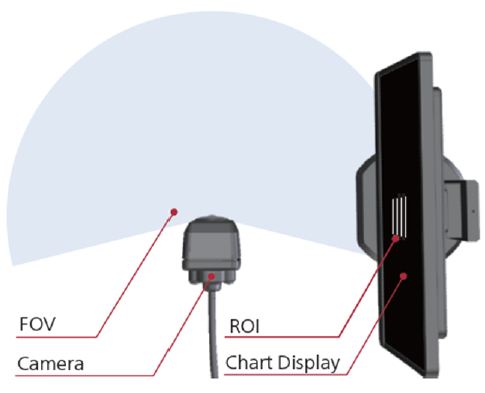
Since the bar chart is switched for each spatial frequency, the measurement area (ROI) is miniaturized and it is possible to measure the partial MTF. For example, you can arbitrarily set the measurement points such as the center of the image and the image height of 40% or 80%.
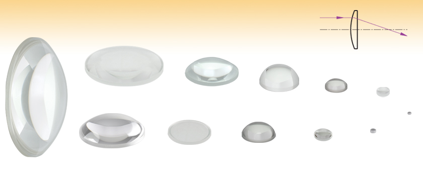
These uncoated Plano-Convex Lenses are fabricated from RoHS-compliant N-BK7 glass. N-BK7 is typically chosen whenever the additional benefits of UV fused silica (i.e., good transmission further into the UV and a lower coefficient of thermal expansion) are not necessary. They have a positive focal length and near-best-form shape for infinite and finite conjugate applications.
Extra-thick retaining rings offer several features that aid in mounting high-curvature optics such as aspheric lenses, short-focal-length plano-convex lenses, and condenser lenses. As shown in the animation to the right, the guide flange of the spanner wrench will collide with the surface of high-curvature lenses when using a standard retaining ring, potentially scratching the optic. This contact also creates a gap between the spanner wrench and retaining ring, preventing the ring from tightening correctly. Extra-thick retaining rings provide the necessary clearance for the spanner wrench to secure the lens without coming into contact with the optic surface.
Disclaimer: The coated transmission data presented here are of 2 mm thick witness samples of N-BK7 or equivalent glass, and all the data here are typical. Some variations in performance data will occur from lot to lot. Please contact Technical Support with any questions regarding the use or reliability of these data.
After displaying a checkerboard chart for analyzing image distortion, multiple sinusoidally modulated patterns are displayed at various spatial frequencies to establish an MTF curve.
MTFlens
Since a test pattern is generated according to the measurement point, it is possible to measure the MTF around a camera with a wide angle of view.
The focal length of a thick spherical lens can be calculated using the thick lens equation below. In this expression, nl is the index of refraction of the lens, R1 and R2 are the radii of curvature for surfaces 1 and 2, respectively, and d is the center thickness of the lens.
Plano-convex lenses can focus a collimated beam or collimate light from a point source. To minimize the introduction of spherical aberration, a collimated light source should be incident on the curved surface of the lens when being focused and a point light source should be incident on the planar surface when being collimated.
Mtf measurementchart
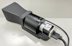
The SFR-Fit measurement system can produce highly accurate measurements of automotive cameras and is compatible with ultra-wide-angle lenses.
Modulation transfer function
Shipping Policy | Privacy Policy | Return Policy | Imatest Terms and Conditions
Thorlabs offers fixed lens mounts that can be used for mounting the lenses sold here. For mounting high-curvature lenses in select sizes, extra-thick retaining rings with SM05 (0.535"-40), SM1 (1.035"-40), or SM2 (2.035"-40) threading are available that provide extra clearance for spanner wrenches (see the Lens Mounting Guide tab for more information).
MTFimage quality
The measurement area can be set by simply clicking and dragging the measurement area (ROI) to the desired location on the image. It is also possible to set by entering numerical values.
when used to calculate the principal plane locations of plano-convex lenses. fb is the back focal length of the lens, which is often referred to as the working distance of the lens.
Modulation transfer function Radiology
MTFcamera
Below is the transmission curve for N-BK7, a RoHS-compliant form of BK7. Total Transmission is shown for a 10 mm thick, uncoated sample and includes surface reflections. Each of these unmounted N-BK7 plano-convex lenses can be ordered uncoated or with one of the following broadband AR coatings: 350 - 700 nm (designated with -A), 400 - 1100 nm (-AB), 650 - 1050 nm (-B), 1050 - 1700 nm (-C), or 1.65 - 3.0 µm (-D).
These high-performance multilayer AR coatings have an average reflectance of less than 0.5% (per surface) across the specified wavelength ranges (except for the -AB and -D coatings, which provide <1.0% average reflectance) and provide good performance for angles of incidence (AOI) between 0° and 30° (0.5 NA). The plot shown below indicates the performance of the standard coatings in this family as a function of wavelength. Broadband coatings have a typical absorption of 0.25%, which is not shown in the reflectance plots.
The focal length of the lens calculated using the simplified thick lens equation directly above is the distance between the second (back) principle plane (H") and the position at which a collimated beam incident on the curved surface of the plano-convex is focused. The principle plane positions of a thick lens can be calculated with the following equations:
where n is the index of refraction and R is the radius of curvature of the lens surface. These lenses are fabricated from N-BK7, which has an Abbe Number of 64.17; this value is an indicator of the dispersion.
These N-BK7 Plano-Convex lenses are also available with one of five antireflection coatings (-A, -AB, -B, -C, or -D), which reduces the amount of light reflected from each surface of the lens (see the Selection Guide table below for links to each coating option). Since approximately 4% of the incident light is reflected at each surface of an uncoated substrate, the application of an AR coating improves transmission, which is important in low-light applications, and prevents the undesirable effects (e.g., ghost images) associated with multiple reflections. Having optics that are AR coated on both surfaces is particularly desirable for applications utilizing multiple optical elements. Please see the Graphs tab for coating information.
SFR-Fit is camera resolution measurement software produced by Leader Electronics Corporation that measures MTF (Modulation Transfer Function), which indicates spatial frequency characteristics. MTF is the spatial frequency characteristic that expresses how faithfully the contrast of the subject for the imaging target can be reproduced and is the most important measurement item for evaluating camera performance.
Conventional MTF measurement methods are generally the slanted edge method based on ISO 12233 or the sine wave method using the Siemens Star chart. Since SFR-Fit generates a test pattern according to the image, it can handle images with large distortions and digitally processed images such as sharpness, which were difficult to measure with conventional methods.
Analysis of distortion of images such as fisheye lenses and correct the distortion of the test pattern. The test pattern generates multiple bar charts with different spatial frequencies and displays them on the display while switching for each spatial frequency. This feature allows you to measure MTF without being affected by image distortion. SFR-Fit automatically performs everything from distortion analysis to measurement, making it easy to measure the MTF of ultra-wide-angle cameras such as fisheye cameras, which has been difficult to measure in the past.
Conventional MTF measurement methods can have issues with black box camera systems that prevent the acquisition of the RAW or minimally processed image. If these systems have sharpening enabled, slanted edges can overstate MTF, especially at high frequencies.
Since the sine wave contrast method is used as the measurement method, it is not easily affected by image noise, and it is possible to measure images that have undergone digital processing, such as sharpening and compression, with excellent accuracy and repeatability.
Displays used as test targets are to be purchased separately. A matte surface display and at least 3x higher display pixel density vs camera resolution are suggested.
Mtf measurementformula
IntroductionThorlabs has a series of quality control procedures in order to ensure our singlets meet our standards and specifications. This starts with in-process inspections of the lens’ imaging capabilities and ends with a final inspection of surface quality and dimensions. Specifications for particular products can be found in their linked documentation by clicking the symbol. This tab will take you through the general process used to check for quality.Singlet Quality PracticesIn-process inspection begins once the singlet has been shaped to specifications. Focal length, surface irregularity, and surface power are checked, following sampling plan Level VI given in MIL-PRF-13830B (see below). These three specifications are imperative for proper imaging. Surface irregularity of parts is kept to below either a quarter wavelength or a half wavelength at 633 nm, depending on the material of the singlet. Below is a graph of over 200 batches of singlets with irregularity data of both their front and back sides.At this point, some uncoated singlets will proceed to final inspection, while others will receive an antireflective (AR) coating. The application of optical coatings has its own in-process inspections. To ensure the AR coating is applied properly, we verify both reflectance and transmission performance by scanning witness pieces using spectrophotometry; the material of these 2 mm thick witness samples matches the other parts in the run. For reflectance verification, we use at least one witness sample for each coating run. Transmitting optics receive two AR coatings, one on each surface, so for the verification of transmission, we use one witness sample that is also coated on both of its sides. Large runs use multiple witness samples to ensure the uniformity across the deposition chamber. By testing coating performance during every run, variance over time is kept low. To see how coatings vary, see the table below.Final inspection of both uncoated and AR-coated singlets includes a batch check of diameter and thickness and a 100% visual check to ensure that the surface quality, chamfer, and clear aperture meet our published specifications. While surface quality is cosmetic to a degree, scratches, digs, and other inclusions in the surface of a part can increase the chances of damage to the singlet when used with high-power sources. These inspections are done in a clean, dark room under lighting that meets the requirements of MIL-PRF-13830B. Inspection under a single light source in a dark room allows for inconsistencies in the glass to be located without being obscured by glare or reflections.MIL-PRF-13830B: Performance Specifications for Optical ComponentsMIL-PRF-13830B is a document created by the U.S. Army Armament Research, Development and Engineering Center's Defense Quality and Standardization Office for the specifications covering how finished optical components should be manufactured, assembled, and inspected. While primarily for use in letting the military dictate how products they use can be incorporated into their equipment, these standards have been adopted by many optics manufacturers. To download a copy of the full document, click here.
Thorlabs' retaining rings are used to secure unmounted optics within lens tubes or optic mounts. These rings are secured in position using a compatible spanner wrench. For flat or low-curvature optics, standard retaining rings manufactured from anodized aluminum are available from Ø5 mm to Ø4". For high-curvature optics, extra-thick retaining rings are available in Ø1/2", Ø1", and Ø2" sizes.
When using the thick lens equation to calculate the focal length of a plano-convex lens, R1=∞ and R2=-R. Note that the minus sign in front of R is due to the sign convention used when deriving the thick lens equations and values of R are reported in the Specs tab as well as on the mechanical drawing for each lens. Therefore, via substitution, the thick lens equation becomes
SFR-Fit is camera resolution measurement software that measures MTF (Modulation Transfer Function). MTF indicates spatial frequency characteristics using multiple distortion and uniformity-corrected sine patterns that can be presented across one or more displays.


 Ms.Cici
 8618319014500