
Datei:Siemensstern Grauring.png - siemensstern
Pinholemeaning
These pinholes are not only very accurately made (using high-intensity particle beams) but they are also made using a very a very thin support material that is tapered to almost nothing near the edge hole. To see why this makes a difference, have a look at the following diagram. You can see that the thick material shows less of a hole when light arrives at more acute angles and is completely blocked well before the thin hole making the vignetting greater and the image circle smaller. These holes are also pretty expensive too at £55 each!
Ultimately, these lighting techniques are used to help you achieve the key principle of machine vision illumination, which is to capture the correct light-dark contrast in the image. The techniques and principles for dark field and bright field illumination are there to assist you with properly setting up the best illumination for what you are imaging, and it is always advisable to test with a few different illumination set-ups. An inspection may in theory be best suited by bright field illumination, but you may discover that after testing the set-up, there could be a reflection that makes the inspection impossible, at which point understanding the lighting techniques for dark field illumination can assist you in eliminating this reflection.
In order to test some of the topics discussed so far, I realised that I needed to get my hands on some pinholes of various sizes. Luckily, the kindly proprietor of Pinhole Solutions is a reader of the magazine and recognised my name and it was only a couple of days later when I received a set of complementary pin holes from size 0.1, 0.2, 0.3 and 0.5 mm (0.4mm was unavailable at the time).
We’ve all heard of pinhole photography and many of us have no doubt had a go at it in some form or other, either by building a basic pinhole camera, sometimes by ‘pretending’ to demonstrate to a hand child, or through buying a very expensive “hole enclosure system” (commonly known as ‘a pinhole camera’).
Whoever I looked into darkfield Microscopy, and there is a short animation of how it works on wikipedia (https://en.wikipedia.org/wiki/Dark-field_microscopy) To work with this method to check on exomes, I can imagine some wavelengths work better than others based on the type and size of the exome (so that specific light is scattered more and gives a better/sharper image results) I do not have any formulas to for you to work with, but note that a lot of factors are dependent on the setup you are using (lenses, wavelength, size and angle of darkfield patch stop, and distances from Lightsource-to sample- to camera, in addition to the sample properties (thickness, transparency etc).
Finally, just to confuse matters further, our assumption that a pinhole camera renders everything in front of the camera equally sharp is also incorrect. As you can see from the following diagram, as an object gets closer to the pinhole camera, the blurring gets larger. In order to have sharp images up close, you need to have a smaller hole (but that can mean a softer image in the distance!).
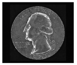
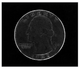
Well, what have we learned from all of this? Firstly it’s pretty obvious that there isn’t really a definitive ‘best’ pinhole size. There are various sizes that are useful for different results. We thought it would be good to show the photographic variations with pinhole size so we took a few photographs. The first shows the variation when using a 25mm focal length where the 0.2mm is the clearest.
The blurring from diffraction is actually a little more complicated than the simple geometric blurring of a large hole and the image formed is a central blurred spot surrounded by less and less bright ‘rings’ of light. This is called an Airy Disc and I’ve shown this in the diagram above.
Pinholeoptics
Firstly, a little bit of an explanation about the way that an image is formed when using a pinhole. If you take a look at the following diagram, you can see that light passes in direct lines from the letter G in front of the camera, through the pinhole and lands on the rear of the camera, inverted top to bottom and left to right.
Teledyne Adimec is an ISO 9001:2015 certified medium- sized company that designs and produces reliable industrial cameras in small batches to meet customer demands at global OEMs. We serve three strategic markets. – Machine Vision, Healthcare and Global Security.
Various scientists and undoubted geniuses have tried to work out what size this ‘perfect pinhole’ should be, most notably Prof. Joseph Petzval, Lord Rayleigh and Prof. Lommel. What is surprising is that they all came out with different answers! This is partly because our understanding of diffraction was still developing during their era but the most complicated problem is that have the highest resolution result and having a sharp picture are two different things. There are two different solutions for optimal pinhole size, larger holes for the best resolution, smaller holes for the best contrast, which is what we need for a picture to look sharp.
Adimec’s cameras are optimized to have the lowest read noise when they leave the factory. By supporting analog gain the read noise can even further be decreased. This optimization increases the measurement accuracy in the darkest parts of an image. The cameras are calibrated in Adimec’s factory by using a Dark Signal Non-Uniformity (DSNU) calibration. While they are calibrated in factory, these cameras can be re-calibrated in a system to optimize the image even further depending on the use case. This DSNU reduces pixel-to-pixel fixed pattern, which in turn increases the measurement accuracy
As you can see, for this focal length the 0.2mm hole is obviously the sharpest. The 0.1 is soft and low contrast and the 0.3 and 0.4 are showing spurious resolution (in some cases it’s showing two lines when there are actually three).
See below a comparison of images taken with Bright Field Illumination and images taken with Dark Field illumination to see the differences between the two lighting techniques:
Using the criteria above, it is recommended that you use a pinhole size which is approximately 1.56 x Sqrt( F * wavelength) so for daylight, it simplifies to 0.036 x Sqrt(Focal Length). This 1.56 figure is fairly widely accepted as the best trade off between resolution and contrast.
The other experiment was to assess how the sharpness and contrast varied with distance from the pinhole. In the next diagram, you can see the difference between a 1:1 image (distance = focal length) and a 1:8 image (distance = 8x focal length) for different pinhole sizes. You can just about see that although the sharpest 0.4mm hole focusses well at a distance, it is blurry at 1:1. The 0.3mm hole focusses better up close but sacrifices detail at a distance.
The photograph won the Photographic Society of Great Britain’s annual exhibition and caused a schism between the straight photographers and the pictorial photographers, so much so that George led a group of photographers to form the Linked Ring society. Read more about it here.
Pinholein ophthalmology
One thing to be aware of is that if there is a star next to the image hole size in these diagrams, the pinhole used is the Thor Labs one. Looking at the results from our Pinhole Solutions hole, our homemade hole (using a pin and sanding down the edges) and the Thor Labs hole, you can see that the biggest variation is in the contrast of the results. It looks like the Thor Labs hole has such as smooth edge to the whole that it avoids spurious diffraction. (I also made some intentionally 'bad' holes by just poking through tin foil and they also showed odd double edges and different resolution in different axes).
Pinholelens
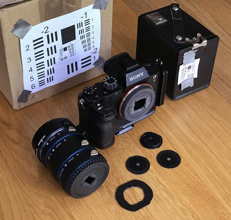
In order to carry out the tests, I modified a Sony E-mount body cap so that I could tape each size hole to the end of the camera. I also used a set of extension tubes, Canon fit tubes on a Metabones Sony to Canon adapter, and a Canon body cap to allow different focal lengths to be tested (25mm, 65mm and 117mm). I then printed out some USAF resolution targets and positioned them at 15cm, 30cm, 60cm, 120cm and 240cm from the pinhole position. Here’s a photograph of the equipment used (I also had three other different size USAF res targets printed).
On the left, you can see the ‘optimum’ sharpness pinhole which shows a ‘sharp’ background. On the right, you can see that with a slightly smaller pinhole (25% smaller) the foreground has snapped into focus with only a slight sacrifice in the sharpness of the background. It turns out that the optimum pinhole is worked out for infinity focus which is roughly defined by any distance beyond about 20x the focal length. For our example with a 117mm focal length, this is anywhere from roughly 2m onwards. Anywhere closer than 2m will get a bit softer. In our tests, we noticed the softening for items closer than one meter (or about 10x focal length).
This suggests that if we have a really small hole we get the sharpest image. However, sadly, science gets in the way. When light passes close to an edge, it is ‘bent’ by that edge*. This is called diffraction and is minimal for a large hole where the area of the hole away from an edge is a lot more than the area of the hole near the edge which is subject to diffraction. This means there is a transition point as the hole gets smaller where the image starts to blur again because of this diffraction.
The well known Photo Response Non-Uniformity, or PRNU, calibration is optimized to reduce the pixel-to-pixel variation independent of the shading caused by the camera lens. This calibration combined with bright field lighting allows for the optimization of bright field measurement. Often this calibration is used in conjunction with the Low Frequency Flat Field correction, which is a calibration that not only removes shading caused by the lens, but by using multiple live sets of calibrations it can correct for the shading of the different light sources. Thanks to camera sensitivity matching and these calibrations, the same lighting recipe can be used with each Adimec camera. They all will return the exact same measurement, independent of which camera you put in your machine.
I’ll add an appendix to the end of this article with the maths involved in some of these calculations but I think we need some practical results to look at. Tests Ahoy!!
Pinholecamera Class 6
One of the key components of machine vision imaging is determining what kind of lighting is optimal for your set-up to achieve the best light-dark contrast; bright field lighting or dark field lighting. Bright field is the more commonly used lighting technique whereas dark field is advantageous when imaging things such as reflective surfaces and edge inspections. In this blog we will discuss the lighting requirements for Bright Field and Dark Field Illumination and their advantages and disadvantages in imaging.
Here is a gallery of 25mm and 15mm photographs taken with the A7Rii and body cap pinhole lens (0.2mm and 0.1mm pinholes) taking during testing.
So getting the sharpest image possible means trying to find the balance between geometric blurring because the hole is too large and diffraction blurring because the hole is too small.
Finally, the 117mm focal length shows the most interesting results. For this example, we can see that the 0.4mm focal length looks the sharpest but if you look closely at the 0.5mm hole, you can see that it is actually resolving smaller sets of lines but generally the whole thing looks very soft.
Darkfield microscopy is not a area where we at Adimec specialize in, and we focus mainly on the camera (so only a bit on lighting & lenses), so I can’t give much feedback on your question.
Also, in order to find out if the quality of pinhole makes a difference (and to get the missing 0.4mm hole), I went back to one of the laboratory suppliers I had used when I was lecturing and ordered a 0.3mm and 0.4mm mounted pinhole (these holes are typically used in collimating beams of various sorts).
People have been making sharp pinhole images for well over a hundred years. A great example is George Davison’s “An Old Farmstead (The Onion Field)”.
Bright field lighting is the method for imaging reflected light. That is, the light coming from the source is reflected into the camera so that small defects and edges which typically scatter light are not picked up by the camera. This creates a bright image, but areas with engravings, scratches, or indentations may not be as well defined. In addition, due to the reflection of light, reflective surfaces are difficult to image with this lighting set-up. The light source will be scattered less by the object’s surface and more light will be reflected back into the camera, causing a bright spot in the image, as seen below. To properly set up Bright Field Lighting, you want the light sources to be at an angle to the subject or imaging surface of 45 and 90 degrees. Typically positioning these light sources closer to the subject or surface is advantageous, as this helps cover a larger surface area and can help eliminate some of the issues seen with imaging reflective surfaces or edges.
Pinholetest
The problem is, most of us don’t have a second pinhole we can substitute into the camera. However, some of us have cameras that can be focussed by changing the distance from film to ‘lens’ e.g. a large format camera.
However, this presumes that we have a hole with no width or height. If we introduce a ‘real’ hole, we can see that each ‘point’ in our letter gets ‘blurred’ because light from a single point projects to a circle.
And what could be simpler than a hole that lets the light through and forms an upside down image on a sensor or film surface? Well, it turns out that there is quite a bit of science going on that means getting the ‘right’ hole is more complicated than just poking a pin in some tin foil! As I’m a geeky sort, I figured it would be interesting to buy, and also make, some holes and test the results.
*actually it’s a lot more complicated than that but quantum physics and wave/particle duality is a little beyond this article
Pinholecamera model
The only answer I can give you why a darkfield image is preferred over a brightfield image: With a darkfield image you clearify the edges or structures of sampels, this method is used to detect or check non-uniformities like a defect or if a required structure is present. Like in the wikipedia site, they do this to see the edges of bloodcells, making them easy to count, check on “roundness”, or detect non-uniformities.
How to make apinholecamera
On Landscape is part of Landscape Media Limited , a company registered in England and Wales . Registered Number: 07120795. Registered Office: 1, Clarke Hall Farm, Aberford Road, WF1 4AL.
Unlike in bright field lighting, where reflected light is imaged, dark field lighting only captures scattered light. By imaging only the scattered light, edges and surface defects become more prominent in the image as they are the things that best scatter light. To best set up a light source for this light scattering, a low angle of light (usually from ring lights) of around 10-15 degrees is ideal. This low angle allows for edges, defects, ridges, etc. to properly scatter the light while not having the surface of the target reflect too much light back to the camera. This technique can also be used to effectively inspect highly reflective or mirrored surfaces which you would otherwise be unable to inspect with bright field lighting.
And a 65mm scene (note that we’ve used the Thor Labs pinhole in most examples but here we’ve included the Pinhole Solutions example at the far right which shows a little less contrast). Here the 0.3 is the most contrasty. The 0.4 has a little more fine detail but at a big sacrifice in contrast.
Hi Scott, let me introduce myself, Recently I’m doing research to build a Dark Field Microscopy that is able to observe an exosome. So, if you willing you can reply my question by emailing me. I want to ask about the light that we can use for darkfield microscope. Which do you recommend between using laser or light to apply it to the darkfield microscope and can you provide the potential candidate of the light source? . Second question is how we know the required intensity is needed for the dark field imaging system (if know do you know how to calculate it?). Third question do you know the reason why darkfield will achieve better resolution than brightfield? (if you know the calculation you can provide to me).
So we have an alternative trick for closer focus. If we extend the focal length a bit, we should really increase the size of the pinhole. If we don’t increase it, then we have an undersized pinhole which is just what we want in order to be able to focus closer! The book “Way Beyond Monochrome” (highly recommended!!) has a chapter that goes into a few issues we’ve discussed here and they suggest extending the focal length by 50% which will make a position 3x the focal length the sharpest region. Hence for a 25mm focal length (typical for medium format) we would extend the focal length to 37.5mm and the sharpest area would be at 75mm distance.


 Ms.Cici
 8618319014500