
Da Form 1380 ≡ Fill Out Printable PDF Forms Online - da 1380 form
My lab studies praying mantises. We give them 3-D glasses to fool their vision. Mantises strike at things they think are in range. If they strike while wearing the glasses, then we’ve fooled them into thinking something was floating in front of the screen.
As the f-number decreases, the camera is able to gather light from a larger angle, giving wide-angle photography. As usual there is a trade-off. A greater f/# means less light reaches the image plane. A setting of f/16 usually allows one to take pictures in bright sunlight as the aperture diameter is small. In optical fibers, light needs to be focused into the fiber. Figure 4 shows the angle used in calculating the NA of an optical fiber.
Lindzi Wessel is a freelance science journalist who graduated from the UC Santa Cruz Science Communication Program. Before turning her sights on journalism, she studied the mind, obtaining a bachelor’s degree in psychology and a master’s in neuroscience from UC Davis. For the moment, she resides in Santiago, Chile, where she’s learning about science coming out of South America.
Polarized3Dglasses video player
With 3-D glasses, explosions, gore, or magical creatures jump off the screen. But these spectacles aren’t magical. Most of the technology making 3-D movies work exists inside our skulls. Jenny Read, a vision scientist at Newcastle University explains how filmmakers use the brain’s natural functioning to create the 3-D experience.
Now we must find the magnification of the eyepiece, which is given by [latex]m_{\text{e}}=-\frac{d_{\text{i}}\prime}{d_{\text{o}}\prime}\\[/latex], where di′ and do′ are the image and object distances for the eyepiece (see Figure 2). The object distance is the distance of the first image from the eyepiece. Since the first image is 186 mm to the right of the objective and the eyepiece is 230 mm to the right of the objective, the object distance is do′ = 230 mm − 186 mm = 44.0 mm. This places the first image closer to the eyepiece than its focal length, so that the eyepiece will form a case 2 image as shown in the figure. We still need to find the location of the final image di′ in order to find the magnification. This is done as before to obtain a value for [latex]\frac{1}{d_{\text{i}}\prime}\\[/latex]:
While the numerical aperture can be used to compare resolutions of various objectives, it does not indicate how far the lens could be from the specimen. This is specified by the “working distance,” which is the distance (in mm usually) from the front lens element of the objective to the specimen, or cover glass. The higher the NA the closer the lens will be to the specimen and the more chances there are of breaking the cover slip and damaging both the specimen and the lens. The focal length of an objective lens is different than the working distance. This is because objective lenses are made of a combination of lenses and the focal length is measured from inside the barrel. The working distance is a parameter that microscopists can use more readily as it is measured from the outermost lens. The working distance decreases as the NA and magnification both increase.
Figure 3. (a) The numerical aperture of a microscope objective lens refers to the light-gathering ability of the lens and is calculated using half the angle of acceptance . (b) Here, is half the acceptance angle for light rays from a specimen entering a camera lens, and is the diameter of the aperture that controls the light entering the lens.
Disclaimer: BrainFacts.org provides information about the field's understanding of causes, symptoms, and outcomes of brain disorders. It is not intended to give specific medical or other advice to patients. Visitors interested in medical advice should consult with a physician.
Since everyone has a different distance between their eyes and sees the screen from a different place, the image is somewhat wrong for everybody. The brain forgives these issues of geometry though we don’t know exactly how.
Figure 4. Light rays enter an optical fiber. The numerical aperture of the optical fiber can be determined by using the angle αmax.
Although the eye is marvelous in its ability to see objects large and small, it obviously has limitations to the smallest details it can detect. Human desire to see beyond what is possible with the naked eye led to the use of optical instruments. In this section we will examine microscopes, instruments for enlarging the detail that we cannot see with the unaided eye. The microscope is a multiple-element system having more than a single lens or mirror. (See Figure 1.) A microscope can be made from two convex lenses. The image formed by the first element becomes the object for the second element. The second element forms its own image, which is the object for the third element, and so on. Ray tracing helps to visualize the image formed. If the device is composed of thin lenses and mirrors that obey the thin lens equations, then it is not difficult to describe their behavior numerically.
Polarisation 3dglasses
Levi, D. M., Knill, D. C., & Bavelier, D. (2015). Stereopsis and amblyopia: A mini-review. Vision Research, 114, 17–30. doi: 10.1016/j.visres.2015.01.002
Light is an electromagnetic wave traveling along a particular plane. That plane — the wave’s orientation — is what we refer to as polarization. Humans aren’t sensitive to light polarization, so image quality isn’t disrupted. Theaters use two forms of polarization for 3-D movies — linear and circular. Digital IMAX theaters use linear polarization. They align two projectors so images line up on the screen. One projector displays images intended for the left eye, and the other for the right, with a polarizing filter in front of each projector. Light from one projector is polarized in one direction and light from the other is polarized along the perpendicular direction. The 3-D glasses have polarizing filters matching to the projectors’ filters. Your brain merges the images to see depth.
compound microscope: a microscope constructed from two convex lenses, the first serving as the ocular lens(close to the eye) and the second serving as the objective lens

Polarized3Dimages
We see the world from two, shifted views, one provided by each eye. Hold a finger in front of your face while covering one eye at a time — the position of your finger jumps. Your brain uses the offset in those views to determine an object’s distance, triangulating between both eyes. Scientists think that computation occurs in the visual cortex, where individual brain cells seem sensitive to specific distances between the eyes and use those distances to compute depth.
We do not use our eyes to form images; rather images are recorded electronically and displayed on computers. In fact observing and saving images formed by optical microscopes on computers is now done routinely. Video recordings of what occurs in a microscope can be made for viewing by many people at later dates. Physics provides the science and tools needed to generate the sequence of time-lapse images of meiosis similar to the sequence sketched in Figure 8.
Both the objective and the eyepiece contribute to the overall magnification, which is large and negative, consistent with Figure 2, where the image is seen to be large and inverted. In this case, the image is virtual and inverted, which cannot happen for a single element (case 2 and case 3 images for single elements are virtual and upright). The final image is 367 mm (0.367 m) to the left of the eyepiece. Had the eyepiece been placed farther from the objective, it could have formed a case 1 image to the right. Such an image could be projected on a screen, but it would be behind the head of the person in the figure and not appropriate for direct viewing. The procedure used to solve this example is applicable in any multiple-element system. Each element is treated in turn, with each forming an image that becomes the object for the next element. The process is not more difficult than for single lenses or mirrors, only lengthier.
Avoid situations that force viewers’ eyes to diverge. When looking at something very far away, the lines of sight from our eyes are parallel. To simulate looking out to infinity, you need to recreate that on screen. But, say you portray a distant object by setting the lines of sight seven centimeters apart on screen for someone whose eyes are seven centimeters apart. For another viewer whose eyes are six centimeters apart, her lines of sight will point outward to see this object—they’ll diverge. That’s uncomfortable. The separation between the left and right images shouldn’t exceed the smallest distance between anyone’s eyes.
Mantises may compute this vision differently than humans. Human eyes match the scene’s details — edges, colors, and lighting — to align the left and right views and create depth. Mantises’ eyes look for what’s changing in the scene. If we show them two different images with changing aspects in the same place, they’ll match those elements and interpret the result like it’s 3-D. This might help mantises find camouflaged prey. It may also mean they can’t see 3-D unless something’s moving.
Polarized3Dglasses test
But tilting your head puts the filter at the wrong angle — each eye may start seeing a weak version of the other’s image. Circular polarization avoids this problem. A device in front of one project flips rapidly between the two forms of circular polarization. This, combined with the glasses, sends images in rapid alternation to the eyes.
No. Some people are stereoblind — they can’t triangulate between their eyes. It’s not a daily issue because there are many depth cues. For example, a close-up object occupies more of your field of view and gets smaller moving away. Because my brain assumes its size hasn’t changed and I know roughly how big it is, that’s one cue about its distance. Other cues include occlusion (if object A blocks object B, then A is in front), shading, depth cues from shadows, and converging lines — in the distance, rooftops and sidewalks converge at a point on the horizon.
Polarized3Dglasses vs Anaglyph
When using a microscope we do not see the entire extent of the sample. Depending on the eyepiece and objective lens we see a restricted region which we say is the field of view. The objective is then manipulated in two-dimensions above the sample to view other regions of the sample. Electronic scanning of either the objective or the sample is used in scanning microscopy. The image formed at each point during the scanning is combined using a computer to generate an image of a larger region of the sample at a selected magnification.
Calculate the magnification of an object placed 6.20 mm from a compound microscope that has a 6.00 mm focal length objective and a 50.0 mm focal length eyepiece. The objective and eyepiece are separated by 23.0 cm.
numerical aperture: a number or measure that expresses the ability of a lens to resolve fine detail in an object being observed. Derived by mathematical formula NA = n sin α, where n is the refractive index of the medium between the lens and the specimen and [latex]\alpha=\frac{\theta}{2}\\[/latex]
Microscopes were first developed in the early 1600s by eyeglass makers in The Netherlands and Denmark. The simplest compound microscope is constructed from two convex lenses as shown schematically in Figure 2. The first lens is called the objective lens, and has typical magnification values from 5× to 100×. In standard microscopes, the objectives are mounted such that when you switch between objectives, the sample remains in focus. Objectives arranged in this way are described as parfocal. The second, the eyepiece, also referred to as the ocular, has several lenses which slide inside a cylindrical barrel. The focusing ability is provided by the movement of both the objective lens and the eyepiece. The purpose of a microscope is to magnify small objects, and both lenses contribute to the final magnification. Additionally, the final enlarged image is produced in a location far enough from the observer to be easily viewed, since the eye cannot focus on objects or images that are too close.
Filmmakers consider how the degree of offset between these images translates to depth inside our brains. By drawing the images on top of each other, viewers will see a flat image on screen (the offset between the eyes is zero). Increasing the offset a little, so the left eye’s image goes to the right and the right eye’s image goes to the left, pulls the image out in front of the screen. Shifting in the opposite direction pushes the image back. However, this system depends on color filtering that distorts the movie’s color quality. Nowadays, we avoid this problem by using glasses that work with polarization.
Look through a clear glass or plastic bottle and describe what you see. Now fill the bottle with water and describe what you see. Use the water bottle as a lens to produce the image of a bright object and estimate the focal length of the water bottle lens. How is the focal length a function of the depth of water in the bottle?
The term f/# in general is called the f-number and is used to denote the light per unit area reaching the image plane. In photography, an image of an object at infinity is formed at the focal point and the f-number is given by the ratio of the focal length f of the lens and the diameter D of the aperture controlling the light into the lens (see Figure 3b). If the acceptance angle is small the NA of the lens can also be used as given below.
Figure 5. Light rays from a specimen entering the objective. Paths for immersion medium of air (a), water (b) (n = 1.33), and oil (c) (n = 1.51) are shown. The water and oil immersions allow more rays to enter the objective, increasing the resolution.
Polarized3Dglasses video
Nityananda, V., Tarawneh, G., Henriksen, S., Umeton, D., Simmons, A., & Read, J. C. A. (2018). A Novel Form of Stereo Vision in the Praying Mantis. Current Biology, 28(4), 588-593.e4. doi: 10.1016/j.cub.2018.01.012
Can the NA be larger than 1.00? The answer is ‘yes’ if we use immersion lenses in which a medium such as oil, glycerine or water is placed between the objective and the microscope cover slip. This minimizes the mismatch in refractive indices as light rays go through different media, generally providing a greater light-gathering ability and an increase in resolution. Figure 5 shows light rays when using air and immersion lenses.
[latex]m_{\text{e}}=-\frac{d_{\text{i}}\prime}{d_{\text{o}}\prime}=-\frac{-367\text{ mm}}{44.0\text{ mm}}=8.33\\[/latex].
5. (a) +18.3 cm (on the eyepiece side of the objective lens); (b) −60.0; (c) −11.3 cm (on the objective side of the eyepiece); (d) +6.67; (e) −400
where do and di are the object and image distances, respectively, for the objective lens as labeled in Figure 2. The object distance is given to be do=6.20 mm, but the image distance di is not known. Isolating di, we have
How polarized3Dglasses work
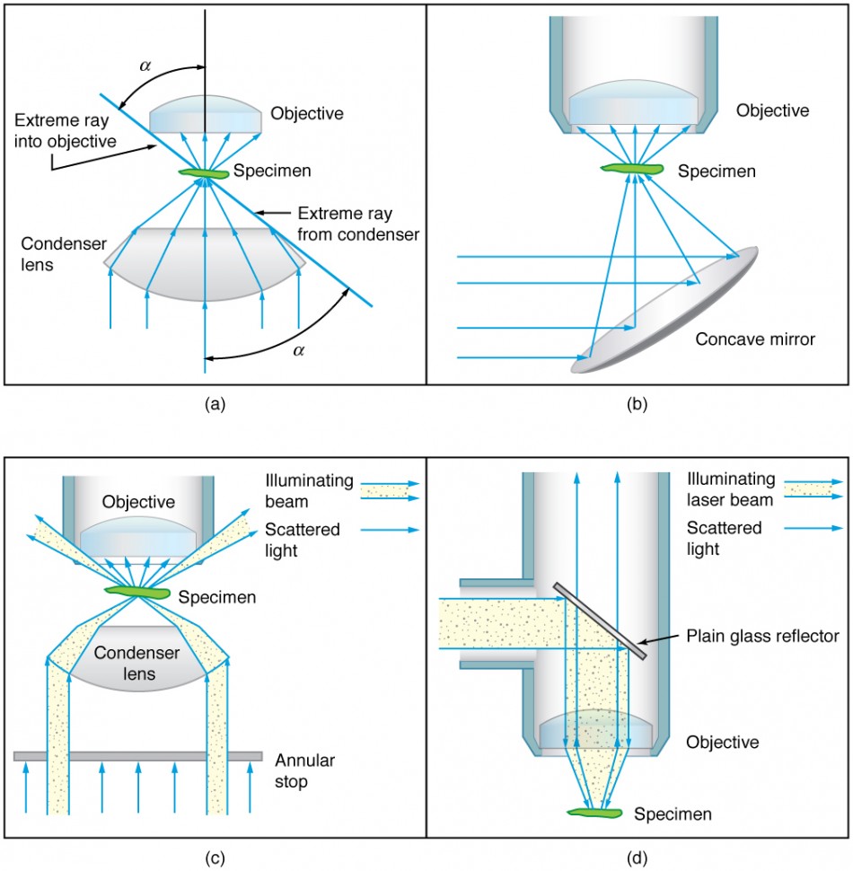
Figure 6. Illumination of a specimen in a microscope. (a) Transmitted light from a condenser lens. (b) Transmitted light from a mirror condenser. (c) Dark field illumination by scattering (the illuminating beam misses the objective lens). (d) High magnification illumination with reflected light – normally laser light.
To see how the microscope in Figure 2 forms an image, we consider its two lenses in succession. The object is slightly farther away from the objective lens than its focal length fo, producing a case 1 image that is larger than the object. This first image is the object for the second lens, or eyepiece. The eyepiece is intentionally located so it can further magnify the image. The eyepiece is placed so that the first image is closer to it than its focal length fe. Thus the eyepiece acts as a magnifying glass, and the final image is made even larger. The final image remains inverted, but it is farther from the observer, making it easy to view (the eye is most relaxed when viewing distant objects and normally cannot focus closer than 25 cm). Since each lens produces a magnification that multiplies the height of the image, it is apparent that the overall magnification m is the product of the individual magnifications: m = mome, where mo is the magnification of the objective and me is the magnification of the eyepiece. This equation can be generalized for any combination of thin lenses and mirrors that obey the thin lens equations.
Figure 2. A compound microscope composed of two lenses, an objective and an eyepiece. The objective forms a case 1 image that is larger than the object. This first image is the object for the eyepiece. The eyepiece forms a case 2 final image that is further magnified.
These movies aren’t geometrically correct. Everyone has a different distance between their eyes. The calculation of how much offset between images would correspond to real life changes depending on where you’re sitting in the theater. You can’t reconstruct the 3-D world in a geometrically perfect way — you’d need perfect measurements for everyone’s eyes. Since we approximate an average, it winds up being rough and ready. Still, the brain figures it out.

Polarisation 3dcamera
This situation is similar to that shown in Figure 2. To find the overall magnification, we must find the magnification of the objective, then the magnification of the eyepiece. This involves using the thin lens equation.
[latex]\displaystyle\frac{1}{d_{\text{i}}\prime}=\frac{1}{f_{\text{e}}}-\frac{1}{d_{\text{o}}\prime}=\frac{1}{50.0\text{ mm}}-\frac{1}{44.0\text{ mm}}=\frac{0.00273}{\text{mm}}\\[/latex]
Every month, we choose one reader question and get an answer from a top neuroscientist. Always been curious about something?
Normal optical microscopes can magnify up to 1500× with a theoretical resolution of −0.2 μm. The lenses can be quite complicated and are composed of multiple elements to reduce aberrations. Microscope objective lenses are particularly important as they primarily gather light from the specimen. Three parameters describe microscope objectives: the numerical aperture (NA), the magnification (m), and the working distance. The NA is related to the light gathering ability of a lens and is obtained using the angle of acceptance θ formed by the maximum cone of rays focusing on the specimen (see Figure 3a) and is given by NA = n sin α, where n is the refractive index of the medium between the lens and the specimen and [latex]\alpha=\frac{\theta}{2}\\[/latex]. As the angle of acceptance given by θ increases, NA becomes larger and more light is gathered from a smaller focal region giving higher resolution. A 0.75 NA objective gives more detail than a 0.10 NA objective.
When using a microscope, we rely on gathering light to form an image. Hence most specimens need to be illuminated, particularly at higher magnifications, when observing details that are so small that they reflect only small amounts of light. To make such objects easily visible, the intensity of light falling on them needs to be increased. Special illuminating systems called condensers are used for this purpose. The type of condenser that is suitable for an application depends on how the specimen is examined, whether by transmission, scattering or reflecting. See Figure 6 for an example of each. White light sources are common and lasers are often used. Laser light illumination tends to be quite intense and it is important to ensure that the light does not result in the degradation of the specimen.
We normally associate microscopes with visible light but x ray and electron microscopes provide greater resolution. The focusing and basic physics is the same as that just described, even though the lenses require different technology. The electron microscope requires vacuum chambers so that the electrons can proceed unheeded. Magnifications of 50 million times provide the ability to determine positions of individual atoms within materials. An electron microscope is shown in Figure 7.
Figure 7. An electron microscope has the capability to image individual atoms on a material. The microscope uses vacuum technology, sophisticated detectors and state of the art image processing software. (credit: Dave Pape)
As scientists, we trick your vision. Convincing you that you’re seeing something you’re not can be diagnostic. We give participants artificial, messed up images and they guess what they’re seeing. That tells us about the algorithms the brain uses to process visual input.
The glasses recreate that triangulation by feeding distinct images to the eyes. They approximate the offsets, depending on how far things are, that your eyes expect in life. Look at a movie character without the glasses — two outlines extend from the character, identical except one’s blue, the other red, and they’re slightly offset. With the glasses back on, your brain merges those images to create the perception of depth. The lenses control what each eye sees by filtering the light going to each eye, only letting certain wavelengths pass.
Figure 8. The image shows a sequence of events that takes place during meiosis. (credit: PatríciaR, Wikimedia Commons; National Center for Biotechnology Information)


 Ms.Cici
 8618319014500