
Controllo Dig. Per Valvola Proporzionale - digper 2
To summarize, for high imaging resolution a high numerical aperture objective is required and one of the consequences of that is a fairly small depth of field which places an emphasis on the quality and performance of your focusing stage and XY sample positioning stage. Dover Motion has developed the DOF-5 specifically for microscope objective focusing.
noun The act of collimating; the adjustment of the line of the sights, as the axial line of the telescope of an instrument, into its proper position relative to ...
The above formulas are approximations. The ISO 14132-1:2002 standard gives the exact calculation for apparent field of view, A F O V , {\displaystyle \ A_{\mathsf {FOV}}\ ,} from the true field of view, T F O V , {\displaystyle \ T_{\mathsf {FOV}}\ ,} as:
field ofview中文
The sample is throwing light out in all directions and the job of the objective is to collect as much of that light as possible. The way to do that is to have a high numerical aperture, a big wide cone. If the objective doesn’t collect a wide-angle of the cone, for example, a long working distance, low power objective will merely be getting the light that’s going straight through. That is why numerical aperture is the key to high-resolution imaging. There is one other variable that can be adjusted. By using bluer light, the resolution can be increased, but for a particular application, that may not be possible. Generally speaking, for any given objective, it is worth it to pay to get the highest possible numerical aperture, but there is a slight downside to that.
Resolving power (Page 2). Resolving power, or resolution, is the smallest distance between two separate points of an object, when viewed with an optical ...
For 20X magnification, which can be a numerical aperture of 0.6 to 0.8, the depth of field drops to about plus or minus 500 nanometers. Moving into high magnification with oil immersion at a numerical aperture of 1.47, the depth of field drops very dramatically, And the depth of field could be plus or minus 0.1 to 0.2 microns (100 – 200 nm). That’s a very tight tolerance. At 100 nanometers or 200 nanometers, very tiny changes in flatness of the sample or the height of the sample, or the precision of the guideways of the XY sample motion stage, will make it tricky to stay in focus. For maintaining focus in this situation, a continuous tracking laser auto-focus system connected to a high bandwidth objective focusing stage, such as the DOF-5, is the ideal way to maintain focus in these high numerical aperture, high-resolution applications.
The generally accepted visual distance of closest focus D {\displaystyle \ D\ } is 250 mm, and eyepiece power is normally specified assuming this value. Common eyepiece powers are 8×, 10×, 15×, and 20×. The focal length of the eyepiece (in mm) can thus be determined if required by dividing 250 mm by the eyepiece power.
Hyperfocal distance calculator
In addition to affecting the observation of the specimen itself, the field of view can also impact the ability to capture high-quality images and videos. A larger field of view requires a larger camera sensor or eyepiece, which can increase the cost of the microscope system. It is essential to consider the balance between field of view, magnification, and cost when selecting and optimizing a microscope for a particular application.
These eyepieces work well with the very long focal length telescopes.[c] This optical design is now considered obsolete since with today's shorter focal length telescopes the eyepiece suffers from short eye relief, high image distortion, axial chromatic aberration, and a very narrow apparent field of view. Since these eyepieces are cheap to make they can often be found on inexpensive telescopes and microscopes.[3]
This is called the depth of field. The formula for the depth of field is: where: “n” is the refractive index of the material between the objective and the sample λ (lambda) is the wavelength of light NA is the Numerical Aperture
A Monocentric is an achromatic triplet lens with two pieces of crown glass cemented on both sides of a flint glass element. The elements are thick, strongly curved, and their surfaces have a common center giving it the name "monocentric". It was invented by H.A. Steinheil around 1883.[9] This design, like the solid eyepiece designs of Tolles, Hastings, and Taylor,[10] is free from ghost reflections and gives a bright contrasty image, a desirable feature when it was invented (before anti-reflective coatings).[11] It has a narrow apparent field of view around 25°[12] but was favored by planetary observers.[13]
Several properties of an eyepiece are likely to be of interest to a user of an optical instrument, when comparing eyepieces and deciding which eyepiece suits their needs.
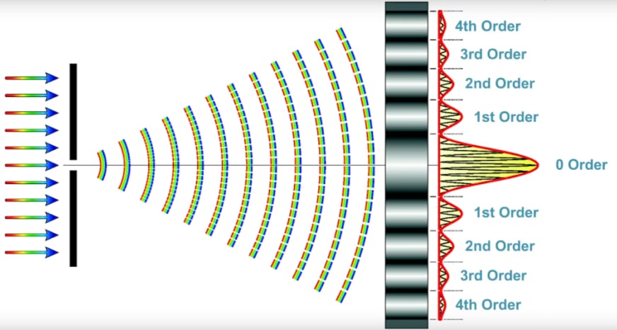
To better understand diffraction imagine if light moved strictly in straight lines. If a pinhole is illuminated with some light, the light would be directed in a straight beam. What actually happens is due to the wave nature of light, the light is diffracted, and instead of going straight, it spreads out into a cone. As shown in the diffraction image, the brightest light is the zero-order straight through, then the intensity decreases for the first order, second order, third order, etc. Unless the objective is capturing all of those higher orders, it is difficult to synthesize a high-resolution image. This describes what the fine structure of your sample is doing, it could be cells, chromosomes, or nuclei, and all of that fine structure spreads the light out.
Invented by Albert Nagler and patented in 1979, the Nagler eyepiece is a design optimized for astronomical telescopes to give an ultra-wide field of view (82°) that has good correction for astigmatism and other aberrations. Introduced in 2007, the Ethos is an enhanced ultra-wide field design developed principally by Paul Dellechiaie under Albert Nagler's guidance at Tele Vue Optics and claims a 100–110° AFOV.[17][18] This is achieved using exotic high-index glass and up to eight optical elements in four or five groups; there are several similar designs called the Nagler, Nagler type 2, Nagler type 4, Nagler type 5, and Nagler type 6. The newer Delos design is a modified Ethos design with a FOV of 'only' 72 degrees but with a long 20 mm eye relief.
Amateur astronomers tend to refer to telescope eyepieces by their focal length in millimeters. These typically range from about 3 mm to 50 mm. Some astronomers, however, prefer to specify the resulting magnification power rather than the focal length. It is often more convenient to express magnification in observation reports, as it gives a more immediate impression of what view the observer actually saw. Due to its dependence on properties of the particular telescope in use, however, magnification power alone is meaningless for describing a telescope eyepiece.
According to Edmund Scientific Corporation, RKE stands for "Rank Kellner Eyepiece'".[citation needed] In an amendment to their trademark application on 16 January 1979 it was given as "Rank-Kaspereit-Erfle", the three designs from which the eyepiece was derived.[15] Edmund Astronomy News (March 1978) called the eyepiece the "Rank-Kaspereit-Erfle" (RKE) a "redesign[ed] ... type II Kellner".[16] However, the RKE deign does not resemble a Kellner, and is closer to a modified König. There is some speculation that at some point the "K" was mistakenly interpreted as the name of the more common Kellner, instead of the fairly rarely seen König.
Eyepieces for telescopes and microscopes are usually interchanged to increase or decrease the magnification, and to enable the user to select a type with certain performance characteristics. To allow this, eyepieces come in standardized "Barrel diameters".
The second formula is actually more accurate, but field stop size is not usually specified by most manufacturers. The first formula will not be accurate if the field is not flat, or is higher than 60° which is common for most ultra-wide eyepiece design.
The same thing occurs in traditional photography, a very small aperture will increase the depth of field. A higher numerical aperture will give a higher resolution, but the depth of field becomes considerably smaller. There is a distance above the sample plane and a distance below the sample plane, and anywhere within them, there is essentially perfect focus. As soon as the objective and sample are outside of that boundary, the image begins to blur.
The field of view, often abbreviated FOV, describes the area of a target (measured as an angle from the location of viewing) that can be seen when looking through an eyepiece. The field of view seen through an eyepiece varies, depending on the magnification achieved when connected to a particular telescope or microscope, and also on properties of the eyepiece itself. Eyepieces are differentiated by their field stop, which is the narrowest aperture that light entering the eyepiece must pass through to reach the field lens of the eyepiece.
An Erfle is a 5 element eyepiece consisting of 2 achromatic doublets with an extra simple lens between them. They were invented by Heinrich Erfle during World War I for military use.[14] The design is an elementary extension of 4 element eyepieces such as Plössls, enhanced for wider fields.
For a low power 4x system, the numerical aperture is going to be very low, on the order of 0.05 to 0.1. In a medium power 40x system, it could be in the range of 0.5 to 0.8 and for a high power system, it can be as high as 0.9 or 0.95. As long as there is air between the objective and the sample, the numerical aperture can never exceed 1. When imaging slides, in order to exceed an NA of 1, a liquid can be added between the coverslip and the objective. Typically, oil or water are used for this and the objectives are referred to as oil immersion or water immersion objectives. With water, the numerical aperture goes up to about 1.1 and using oil, the numerical aperture can go up to as high as 1.47.
A simple convex lens placed after the focus of the objective lens presents the viewer with a magnified inverted image. This configuration may have been used in the first refracting telescopes from the Netherlands and was proposed as a way to have a much wider field of view and higher magnification in telescopes in Johannes Kepler's 1611 book Dioptrice. Since the lens is placed after the focal plane of the objective it also allowed for use of a micrometer at the focal plane (used for determining the angular size and/or distance between objects observed).
An eyepiece consists of several "lens elements" in a housing, with a "barrel" on one end. The barrel is shaped to fit in a special opening of the instrument to which it is attached. The image can be focused by moving the eyepiece nearer and further from the objective. Most instruments have a focusing mechanism to allow movement of the shaft in which the eyepiece is mounted, without needing to manipulate the eyepiece directly.
By convention, microscope eyepieces are usually specified by power instead of focal length. Microscope eyepiece power P E {\displaystyle \ P_{\mathrm {E} }\ } and objective power P O {\displaystyle \ P_{\mathsf {O}}\ } are defined by
Erfle eyepieces are designed to have wide field of view (about 60°), but are unusable at high powers because they suffer from astigmatism and ghost images.[d] However, with lens coatings at low powers (focal lengths of 20~30 mm and up) they are acceptable, and at 40 mm they can be excellent. Erfles are very popular for wide-field views, because they have large eye lenses, and can be very comfortable to use because of their good eye relief in longer focal lengths.
Huygens eyepieces consist of two plano-convex lenses with the plane sides towards the eye separated by an air gap. The lenses are called the eye lens and the field lens. The focal plane is located between the two lenses. It was invented by Christiaan Huygens in the late 1660s and was the first compound (multi-lens) eyepiece.[2] Huygens discovered that two air spaced lenses can be used to make an eyepiece with zero transverse chromatic aberration. If the lenses are made of glass of the same Abbe number, to be used with a relaxed eye and a telescope with an infinitely distant objective then the separation is given by:
When designing automated digital microscopy devices for life science, biomedical, and diagnostic applications, typically, our goal is to optimize the device for the highest resolution image and the highest throughput in images per second. Microscope calculations such as magnification, resolution, microscope field of view, depth of field, and numerical aperture help us determine various aspects of a microscope’s capabilities and simplify the modeling and prototyping process. In this article, we will cover the importance of microscope calculations in optimizing microscope performance for your specific application.
In most cases the material between the objective and sample is air, and “n” equals 1.00. For water, it’s refractive index is 1.33, and specialized immersion oil for microscopy is 1.52. For a low magnification objective such as a 4X or even a 10X, the typical depth of field is plus or minus 3 to 5 microns. In that case, if the sample is very flat, focusing may not be required at all, or only one needs to happen one time. Generally speaking, samples vary in thickness and they vary in flatness, so focusing is required.
Internal reflections, sometimes called "scatter", cause the light passing through an eyepiece to disperse and reduce the contrast of the image projected by the eyepiece. When the effect is particularly bad, "ghost images" are seen, called "ghosting". For many years, simple eyepiece designs with a minimum number of internal air-to-glass surfaces were preferred to avoid this problem.
It is common for users of an eyepiece to want to calculate the actual field of view, because it indicates how much of the sky will be visible when the eyepiece is used with their telescope. The most convenient method of calculating the actual field of view depends on whether the apparent field of view is known.
Eyepieces are optical systems where the entrance pupil is invariably located outside of the system. They must be designed for optimal performance for a specific distance to this entrance pupil (i.e. with minimum aberrations for this distance). In a refracting astronomical telescope the entrance pupil is identical with the objective. This may be several feet distant from the eyepiece; whereas with a microscope eyepiece the entrance pupil is close to the back focal plane of the objective, mere inches from the eyepiece. Microscope eyepieces may be corrected differently from telescope eyepieces; however, most are also suitable for telescope use.
Microscope calculations are specific to the imaging sensor and microscope objective selection, which also impacts the performance requirements of the sample XY motion and Z focusing motion.
where f A {\displaystyle \ f_{\mathsf {A}}\ } and f B {\displaystyle \ f_{\mathsf {B}}\ } are the focal lengths of the component lenses.
... Western, Warrington Bank Quay, Manchester Victoria Tour Destination: York. Enjoy a fabulous day tour travelling through the impressive Pennines over two very ...
Since M = f T f E , {\displaystyle \ M={\frac {\ f_{\mathsf {T}}\ }{f_{\mathsf {E}}}}\ ,} where:
In the previous example we considered a sensor with 4 micron pixels used with an objective with 40X magnification and a numerical aperture of 0.8. The sensor and magnification provide 100 nm geometric resolution. However, due to diffraction, the sample image resolution will be greater than 100 nm. For example, yellow green light has a wavelength lambda of 550 nm. Using the above equation, the diffraction limited resolution is actually 419 nm. Therefore, the resolution of the sample is > 4 times the geometric resolution at the camera sensor which results in oversampling. While some oversampling is appropriate, 4 times is excessive and a waste of sensor pixels. Calculate the diffraction using our calculator.
In this video, we will explain key optical imaging formulas and how they help in designing your automated digital microscopy imaging applications. Download Microscopy Calculator
About product and suppliers. 67 photomultiplier tube hamamatsu products are offered for sale by suppliers on Alibaba.com, of which microcontrollers and ...
A separation of exactly 1 focal length is also inadvisable since it renders the dust on the field lens disturbingly in focus. The two curved surfaces face inwards. The focal plane is thus located outside of the eyepiece and is hence accessible as a location where a graticule, or micrometer crosshairs may be placed. Because a separation of exactly one focal length would be required to correct transverse chromatic aberration, it is not possible to correct the Ramsden design completely for transverse chromatic aberration. The design is slightly better than Huygens but still not up to today's standards.
There are six standard barrel diameters for telescopes. The barrel sizes (usually expressed in inches[citation needed]) are:
Covers key formulas for selecting the optimal imaging sensor and microscope objective for your digital imaging application including sensor size, magnification, field of view, pixel sizes, resolution, depth of field, and numerical aperture.
The image below shows a variety of microscope systems. There are multiple magnification objectives depicted: low power 4x, medium power, 40x and high power 100x. The distance from the end of the objective to the sample, which is called the working distance, is going to be larger on a low power objective, less on a medium power and very fine, possibly a fraction of a millimeter for the high power system. What’s critical is the angle. The sample is illuminated and light is coming out of it. In the case of the shorter working distance, higher numerical aperture objectives, that light is coming at an increasingly higher angle. The Numerical Aperture (NA) of the objective equals the sine of the half-angle (theta divided by two where theta is the entire angle). Read more on how to calculate the numerical aperture.
The Plössl eyepiece was an obscure design until the 1980s when astronomical equipment manufacturers started selling redesigned versions of it.[7] Today it is a very popular design on the amateur astronomical market,[8] where the name Plössl covers a range of eyepieces with at least four optical elements, sometimes overlapping with the Erfle design.
Modern instruments often use objectives optically corrected for an infinite tube length rather than 160 mm, and these require an auxiliary correction lens in the tube.
An eyepiece, or ocular lens, is a type of lens that is attached to a variety of optical devices such as telescopes and microscopes. It is named because it is usually the lens that is closest to the eye when someone looks through an optical device to observe an object or sample. The objective lens or mirror collects light from an object or sample and brings it to focus creating an image of the object. The eyepiece is placed near the focal point of the objective to magnify this image to the eyes. (The eyepiece and the eye together make an image of the image created by the objective, on the retina of the eye.) The amount of magnification depends on the focal length of the eyepiece.
Longitudinal chromatic aberration is a pronounced effect of optical telescope objectives, because the focal lengths are so long. Microscopes, whose focal lengths are generally shorter, do not tend to suffer from this effect.
When it comes to digital imaging sensors, there is a wide variety to choose from. The main camera sensors used are CCD (charge-coupled device) or CMOS, Complementary Metal Oxide Semiconductor. For cutting edge performance, to reduce read noise, large and expensive cameras exist with liquid or Peltier coolers (deep cooled to about -60 degrees Celsius). Also, EMCCD (Electron Multiplied CCD) cameras allow for single photon detection and are popular for live cell imaging applications. Learn more about key aspects of image sensors common to both CCD and CMOS devices, starting at the pixel level in our "CCD Image Sensors" whitepaper.
Viewangle
Magnification increases, therefore, when the focal length of the eyepiece is shorter or the focal length of the objective is longer. For example, a 25 mm eyepiece in a telescope with a 1200 mm focal length would magnify objects 48 times. A 4 mm eyepiece in the same telescope would magnify 300 times.
The 4-element orthoscopic eyepiece consists of a plano-convex singlet eye lens and a cemented convex-convex triplet field lens achromatic field lens. This gives the eyepiece a nearly perfect image quality and good eye relief, but a narrow apparent field of view — about 40°–45°. It was invented by Ernst Abbe in 1880.[3] It is called "orthoscopic" or "orthographic" because of its low degree of distortion and is also sometimes called an "ortho" or "Abbe".
Besides the magnification, reducing the size of the sensor down to the size of the field of view on the sample also does the same with the pixels. For example, a sensor with 4 micron pixels and a 40X objective would be 0.1 micron of geometric resolution or 100 nanometers. But it turns out it isn’t quite that simple. There’s a property of light that acts like a particle, the photon. It also has a wave property. The wave nature of light leads to a condition called diffraction, and due to diffraction, limits are set on resolution. To better understand how that works, we need to explore another concept, which is called numerical aperture.
The total angular magnification of a microscope image is then simply calculated by multiplying the eyepiece power by the objective power. For example, a 10× eyepiece with a 40× objective will magnify the image 400 times.
The first eyepieces had only a single lens element, which delivered highly distorted images. Two and three-element designs were invented soon after, and quickly became standard due to the improved image quality. Today, engineers assisted by computer-aided drafting software have designed eyepieces with seven or eight elements that deliver exceptionally large, sharp views.
Because Huygens eyepieces do not contain cement to hold the lens elements, telescope users sometimes use these eyepieces in the role of "solar projection", i.e. projecting an image of the Sun onto a screen for prolonged periods of time. Cemented eyepieces are traditionally regarded as potentially vulnerable to heat damage by the intense concentrations of light involved.
Field of view
The focal length of an eyepiece is the distance from the principal plane of the eyepiece to where parallel rays of light converge to a single point. When in use, the focal length of an eyepiece, combined with the focal length of the telescope or microscope objective, to which it is attached, determines the magnification. It is usually expressed in millimetres when referring to the eyepiece alone. When interchanging a set of eyepieces on a single instrument, however, some users prefer to identify each eyepiece by the magnification produced.
FOVtofocal length calculator
The microscope field of view stands for the area of the sample visible through the microscope, which is calculated by dividing the sensor diagonal size by the magnification of the objective lens. For instance, a 20 mm diagonal sensor with a 20X objective lens would yield a Field Of View (FOV) of 1 mm, typical for microscopy applications. Microscope field of view can be calculated using the following formula:
We received the 2 headed ax and the resin never cured. It was out in the sun for 4 hours and didn't cure so we tried my UV crafting light, same issue. The ...
Table of Contents · Objective Identification · M = L / F . · NA = ni × sinθ · FN = Field of View Diameter × Magnification · Magnification · Using an Objective with a ...
All exclusive frames distributed by EO Executive Optical with free multicoated lens. 20%. Participating branch/es: NO. BRANCH. ADDRESS. 1. EO ALABANG TOWN ...
The simple negative lens placed before the focus of the objective has the advantage of presenting an erect image but with limited field of view better suited to low magnification. It is suspected this type of lens was used in some of the first refracting telescopes that appeared in the Netherlands in about 1608. It was also used in Galileo Galilei's 1609 telescope design which gave this type of eyepiece arrangement the name "Galilean". This type of eyepiece is still used in very cheap telescopes, binoculars and in opera glasses.
Eye relief typically ranges from about 2 mm to 20 mm, depending on the construction of the eyepiece. Long focal-length eyepieces usually have ample eye relief, but short focal-length eyepieces are more problematic. Until recently, and still quite commonly, eyepieces of a short-focal length have had a short eye relief. Good design guidelines suggest a minimum of 5–6 mm to accommodate the eyelashes of the observer to avoid discomfort. Modern designs with many lens elements, however, can correct for this, and viewing at high power becomes more comfortable. This is especially the case for spectacle wearers, who may need up to 20 mm of eye relief to accommodate their glasses.
If the apparent field of view is known, the actual field of view can be calculated from the following approximate formula:
fov和焦距的关系
The König eyepiece has a concave-convex positive doublet and a plano-convex singlet. The strongly convex surfaces of the doublet and singlet face and (nearly) touch each other. The doublet has its concave surface facing the light source and the singlet has its almost flat (slightly convex) surface facing the eye. It was designed in 1915 by German optician Albert König (1871−1946)[citation needed] and is effectively a simplified Abbe. The design allows for high magnification with remarkably high eye relief – the longest eye relief proportional to focal length of any design before the Nagler, in 1979. The field of view of about 55° is slightly superior to the Plössl, with the further advantages of better eye relief and requiring one less lens element.
The number of elements in a Nagler makes them seem complex, but the idea of the design is fairly simple: every Nagler has a negative doublet field lens, which increases magnification, followed by several positive groups. The positive groups, considered separate from the first negative group, combine to have long focal length, and form a positive lens. That allows the design to take advantage of the many good qualities of low power lenses. In effect, a Nagler is a superior version of a Barlow lens combined with a long focal length eyepiece. This design has been widely copied in other wide field or long eye relief eyepieces.
G Smith · 2001 · 245 — More negative values will give a positive aberration. Therefore, we may expect that the posterior surface probably contributes a small amount of positive ...
where Sensor Diagonal is the diagonal size of the camera sensor in millimeters (similar to specifying a TV size), and Objective Magnification is the magnification of the objective lens being used.
One solution is to reduce the aberration by using multiple elements of different types of glass. Achromats are lens groups that bring two different wavelengths of light to the same focus and exhibit greatly reduced false colour. Low dispersion glass may also be used to reduce chromatic aberration.
To optimize the field of view for a particular application, it is vital to consider the size of the specimen and the level of detail required. For example, if a large sample with low detail is being observed, a lower magnification and larger field of view may be more appropriate. Conversely, if a smaller specimen with high detail is being observed, a higher magnification and smaller field of view may be necessary to achieve the desired level of resolution.
Elements are the individual lenses, which may come as simple lenses or "singlets" and cemented doublets or (rarely) triplets. When lenses are cemented together in pairs or triples, the combined elements are called groups (of lenses).
DOF calculator
Oct 22, 2024 — Having a filter when using a laser cutter/engraver is important for maintaining a safe and breathable environment while working. Just as you ...
Modern improvements typically have fields of view of 60°−70°. König design revisions use exotic glass and / or add more lens groups; the most typical adaptation is to add a simple positive, concave-convex lens before the doublet, with the concave face towards the light source and the convex surface facing the doublet.
This definition of lens power relies upon an arbitrary decision to split the angular magnification of the instrument into separate factors for the eyepiece and the objective. Historically, Abbe described microscope eyepieces differently, in terms of angular magnification of the eyepiece and 'initial magnification' of the objective. While convenient for the optical designer, this turned out to be less convenient from the viewpoint of practical microscopy and was thus subsequently abandoned.
Field of viewvs angleof view
If a diagonal or Barlow lens is used before the eyepiece, the eyepiece's field of view may be slightly restricted. This occurs when the preceding lens has a narrower field stop than the eyepiece's, causing the obstruction in the front to act as a smaller field stop in front of the eyepiece. The exact relationship is given by
The eye needs to be held at a certain distance behind the eye lens of an eyepiece to see images properly through it. This distance is called the eye relief. A larger eye relief means that the optimum position is farther from the eyepiece, making it easier to view an image. However, if the eye relief is too large it can be uncomfortable to hold the eye in the correct position for an extended period of time, for which reason some eyepieces with long eye relief have cups behind the eye lens to aid the observer in maintaining the correct observing position. The eye pupil should coincide with the exit pupil, the image of the entrance pupil, which in the case of an astronomical telescope corresponds to the object glass.
Lateral or transverse chromatic aberration is caused because the refraction at glass surfaces differs for light of different wavelengths. Blue light, seen through an eyepiece element, will not focus to the same point but along the same axis as red light. The effect can create a ring of false colour around point sources of light and results in a general blurriness to the image.
The consequence of numerical aperture is that it directly relates to the Depth Of Field (DOF). For a given objective, looking at a sample, there’s a particular plane of perfect focus. The depth of field is, how far above and below that plane the objective and sample can be and still have everything in focus.
by R Heilmann · 2022 · Cited by 43 — In a finite system, emission occurs primarily at the edges and corners of the sample, both in theory and experiments. Our quasi-BIC lasing mode ...
A larger field of view is generally desirable, as it allows for a larger area of the sample to be viewed at once, making it easier to locate and navigate to specific areas of interest. However, as the magnification increases, the field of view decreases, making it more difficult to observe larger areas of the specimen at higher magnifications. Need help with microscope calculations? Download our calculator.
In a Kellner eyepiece an achromatic doublet is used in place of the simple plano-convex eye lens in the Ramsden design to correct the residual transverse chromatic aberration. Carl Kellner designed this first modern achromatic eyepiece in 1849,[4] also called an "achromatized Ramsden". Kellner eyepieces are a 3-lens design. They are inexpensive and have fairly good image from low to medium power and are far superior to Huygenian or Ramsden design. The eye relief is better than the Huygenian and worse than the Ramsden eyepieces.[5] The biggest problem of Kellner eyepieces was internal reflections. Today's anti-reflection coatings make these usable, economical choices for small to medium aperture telescopes with focal ratio f/6 or longer. The typical apparent field of view is 40–50°.
Technology has developed over time and there are a variety of eyepiece designs for use with telescopes, microscopes, gun-sights, and other devices. Some of these designs are described in more detail below.
The Ramsden eyepiece comprises two plano-convex lenses of the same glass and similar focal lengths, placed less than one eye-lens focal length apart, a design created by astronomical and scientific instrument maker Jesse Ramsden in 1782. The lens separation varies between different designs, but is typically somewhere between 7 /10 and 7 /8 of the focal length of the eye-lens, the choice being a trade off between residual transverse chromatic aberration (at low values) and at high values running the risk of the field lens touching the focal plane when used by an observer who works with a close virtual image such as a myopic observer, or a young person whose accommodation is able to cope with a close virtual image (this is a serious problem when used with a micrometer as it can result in damage to the instrument).
The eyepieces of binoculars are usually permanently mounted in the binoculars, causing them to have a pre-determined magnification and field of view. With telescopes and microscopes, however, eyepieces are usually interchangeable. By switching the eyepiece, the user can adjust what is viewed. For instance, eyepieces will often be interchanged to increase or decrease the magnification of a telescope. Eyepieces also offer varying fields of view, and differing degrees of eye relief for the person who looks through them.
The main disadvantage to Naglers is in their weight; they are often ruefully referred to as ‘hand grenades’ because of their heft and large size. Long focal length versions exceed 0.5 kg (1.1 lb), which is enough to unbalance small to medium-sized telescopes. Another disadvantage is a high purchase cost, with large Naglers' prices comparable to the cost of a small telescope. Hence these eyepieces are regarded by many amateur astronomers as a luxury.[19]
For a telescope, the approximate angular magnification M A {\displaystyle \ M_{\mathsf {A}}\ } produced by the combination of a particular eyepiece and objective can be calculated with the following formula:
The Plössl is an eyepiece usually consisting of two sets of doublets, designed by Georg Plössl in 1860. Since the two doublets can be identical this design is sometimes called a symmetrical eyepiece.[6] The compound Plössl lens provides a large 50° or more apparent field of view, along with the proportionally large true FOV. This makes this eyepiece ideal for a variety of observational purposes including deep-sky and planetary viewing. The chief disadvantage of the Plössl optical design is short eye relief compared to an orthoscopic, since the Plössl eye relief is restricted to about 70–80% of focal length. The short eye relief is more critical in short focal lengths below about 10 mm, when viewing can become uncomfortable – especially for people wearing glasses.
Until the advent of multicoatings and the popularity of the Plössl, orthoscopics were the most popular design for telescope eyepieces. Even today these eyepieces are considered good eyepieces for planetary and lunar viewing. They are preferred for reticle eyepieces, since they are one of the wide-field, long eye-relief designs with an external focal plane; slowly being supplanted by the König. Due to their low degree of distortion and the corresponding globe effect, they are less suitable for applications which require an extensive panning of the instrument.
The focal length of the telescope objective, f T , {\displaystyle \ f_{\mathsf {T}}\ ,} is the diameter of the objective times the focal ratio. It represents the distance at which the mirror or objective lens will cause light from a star to converge onto a single point (aberrations excepted).
An RKE eyepiece has an achromatic field lens and double convex eye lens, a reversed adaptation of the Kellner eyepiece, with its lens layout similar to the König. It was designed by Dr. David Rank for the Edmund Scientific Corporation, who marketed it throughout the late 1960s and early 1970s. This design provides slightly wider field of view than classic Kellner design and makes its design similar to a widely spaced version of the König.
This formula also indicates that, for an eyepiece design with a given apparent field of view, the barrel diameter will determine the maximum focal length possible for that eyepiece, as no field stop can be larger than the barrel itself. For example, a Plössl with 45° apparent field of view in a 1.25 inch barrel would yield a maximum focal length of 35 mm.[1] Anything longer requires larger barrel or the view is restricted by the edge, effectively making the field of view less than 45°.
One solution to scatter is to use thin film coatings over the surface of the element. These thin coatings are only one or two wavelengths deep, and work to reduce reflections and scattering by changing the refraction of the light passing through the element. Some coatings may also absorb light that is not being passed through the lens in a process called total internal reflection where the light incident on the film is at a shallow angle.
In some eyepiece types, such as Ramsden eyepieces (described in more detail below), the eyepiece behaves as a magnifier, and its focal plane is located outside of the eyepiece in front of the field lens. This plane is therefore accessible as a location for a graticule or micrometer crosswires. In the Huygenian eyepiece, the focal plane is located between the eye and field lenses, inside the eyepiece, and is hence not accessible.
This eyepiece is one of the more expensive to manufacture because of the quality of glass, and the need for well matched convex and concave lenses to prevent internal reflections. Due to this fact, the quality of different Plössl eyepieces varies. There are notable differences between cheap Plössls with simplest anti-reflection coatings and well made ones.


 Ms.Cici
 8618319014500