
Control Systems - vision controlling
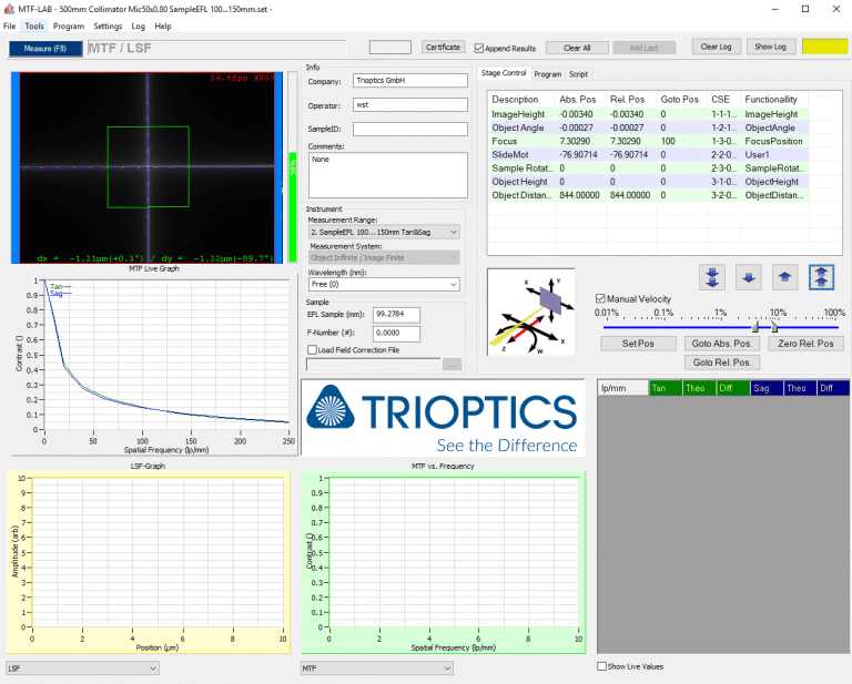
Step 8: Under “Relative Illumination” button, adjusting “Focus” parameter and sample position to ensure that CCD is on image plane, and receives the generated image. As examples shown, if the image is black representing no energy is received at this position, operator needs to re-adjust, until the image turns into red, representing sufficient energy is received.
Step 6: Adjust the “Slide Mot” parameter to adjust the sample stand’s height, ensuring the entrance pupil of the sample lens in the center of the collimator’s swing arm.
80 50 scratch-dig
Step 9: Switch to corresponded sample EFL and wavelength under “measurement range” page, cross wire will be shown in the display area. Avantier has abundant filters in stock making sure broad range of wavelengths can be measured at this stage.
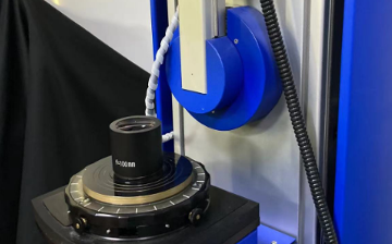
Step 1: Equip with collimators with different EFL (50mm/300mm/500mm), Avantier is available to measure according to different customers’ requirements.
Step 4: Place sample lens in place, where above image plane, and beneath light source, while turning on stepper motor and light source.
surface quality 60-40
VIETNAM:Alpha Industrial Park, Tu ThonVillage, Yen My District, HungYen Province 17721+84 221-730-8668sales-vn@avantierinc.com
Step 2: Select whether the testing sample is an infinite or finite conjugate lens and focal length, enables to test on various lenses.
MIL-PRF-13830B is a critical specification that outlines the standards for the quality and durability of optical components and assemblies used primarily in military applications. This specification is essential for ensuring that optical parts meet the rigorous demands of military environments, where reliability and performance cannot be compromised.
C7641866
iso 10110-7
Surface quality, in particular, is evaluated based on a system that grades scratches and digs on the optical surfaces. This grading system helps in determining the acceptability of optical components for military use.
In summary, the objective lens MTF testing is an indispensable process at the heart of Avantier’s optical manufacturing prowess. Through rigorous MTF analysis, we gain deep insights into the true capabilities of our lenses, ensuring they meet the highest standards of contrast, sharpness, and resolution. This commitment to precision and quality defines Avantier’s dedication to delivering optical solutions that empower industries and push the boundaries of clarity and performance.
mil-c-675
With an in-house ImageMaster® HR MTF station, Avantier is able to provide an outstanding level of accuracy and flexibility in testing the MTF. Following is the common procedure to measure MTF for an optical lens assembly.
Step 3: Switch to the corresponding collimator when necessary. Connect the light source and stepper motor at the same time to set up.
Avantier has ImageMaster® TriOptics MTF Stations in-house, with the capability to handle MTF testing, enabling the precise determination of the imaging quality of lenses and optical systems.
iso 10110-7 pdf
Step 7: Adjust the “Focus” parameter to adjust CCD’s height. Based on BFL of the lens, it determines how close the CCD to the image plane.
MIL-PRF-13830B is vital for military applications due to the demanding conditions in which military optical systems operate. High-quality optical components are essential for the performance and reliability of devices such as targeting systems, surveillance equipment, and navigation aids. Adherence to MIL-PRF-13830B ensures that optical components can withstand harsh environments without degradation in performance.
For further services, MTF testing data will be provided to the optical system and assemblies’ deliveries, and optical components upon request.
mil-prf-13830b pdf
Modulation Transfer Function (MTF) is a fundamental concept in optics and image quality assessment that quantifies how well a lens system is able to reproduce various spatial frequencies in an image.
In summary, MIL-PRF-13830B is a comprehensive specification that sets the standard for the quality and durability of optical components used in military applications. It provides clear criteria for surface quality, including a grading system for scratches and digs, ensuring that optical components meet the high standards required for military use.
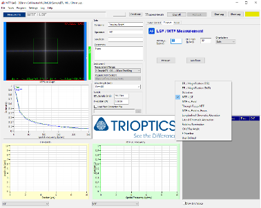
Step 11: Input corresponded line number and edited txt document under “MTF vs Field” page to generate the complete testing curve.
mil-c-48497
Below are MTF plots and tables of one of our 20X customized objective lenses. With Avantier’s design and manufacturing capabilities, we can fully meet customer’s requirements, as shown in result of MTF measured at from 100lp/mm to 400lp/mm in both tangential and sagittal directions.
It establishes the correlation between the output and input within an optical system and stands as the most comprehensive method for such an evaluation, it involves various parameters, including resolution, sensitivity, physical geometry, and noise. Alternatively expressed in cycles, lines, or line pairs per millimeter, MTF can be measured for both lens components and optical assembly.
The scratch and dig numbers are a crucial part of MIL-PRF-13830B. They provide a standardized method to describe the surface imperfections on optical components. A scratch number represents the width of the scratch, while a dig number represents the diameter of a dig or pit. These numbers are used to specify the allowable limits of surface imperfections for optical components under this specification.


 Ms.Cici
 8618319014500