
Compound Microscope Parts - objective lens microscope definition
Edmund Scientific Lab Equipment For Sale. Huge selection of lab equipment for sale. We have been in business since 1974. Shipping worldwide.
When people think of a handheld magnifier they probably imagine a classic Sherlock Holmes magnifying glass but it's just one of many hand magnifiers we ...
For large aspheric departure, to avoid the re-trace error, Wyant proposed to place the CGH in the testing arm, using it as a null lens. This becomes the most popular test configuration nowadays.
Beam diameter is also important to know when comparing damage thresholds. While the LIDT, when expressed in units of J/cm², scales independently of spot size; large beam sizes are more likely to illuminate a larger number of defects which can lead to greater variances in the LIDT [4]. For data presented here, a <1 mm beam size was used to measure the LIDT. For beams sizes greater than 5 mm, the LIDT (J/cm2) will not scale independently of beam diameter due to the larger size beam exposing more defects.
The passbands of these filters range from 1 to 40 nm FWHM, depending on the center wavelength chosen, with steep cut-on and cut-off slopes. The center wavelength and passbands for these filters are specified for light normally incident on the surface. For angles of incidence (AOIs) greater than 0°, the band will shift toward a lower center wavelength and the shape of the passband will change. Filters with passbands that have full width half maxima (FWHM) in the 1 to 5 nm range are particularly susceptible to these shifts. For more information, see the Tutorial tab.
by L Orazi · 2021 · Cited by 70 — Abstract. Modern ultrafast lasers are enabling better operative performances in micro and nano-fabrications of materials, benefited from their ease of use, ...
A bandpass filter is created by depositing layers of material on the surface of the substrate. For our hard-coated bandpass filters, the coating is comprised of dielectric stacks alternating with dielectric spacer layers. Each dielectric stack is composed of a large number of alternating layers of low-index and high-index material. The thickness of each layer in the dielectric stack is λ/4, where λ is the design center wavelength of the bandpass filter (i.e. the wavelength designed to have highest transmittance through the filter at normal incidence). The spacer layers are placed in between the stacks and have a thickness of (nλ)/2, where n is an integer. A Fabry-Perot cavity is formed by each spacer layer sandwiched between dielectric stacks. The filter is mounted in an engraved metal ring for protection and ease of handling.
Please note that we have a buffer built in between the specified damage thresholds online and the tests which we have done, which accommodates variation between batches. Upon request, we can provide individual test information and a testing certificate. Contact Tech Support for more information.
The filter is intended to be used with collimated light normally incident on the surface of the filter. For uncollimated light or light striking the surface at an angle not normally incident to the surface, the center wavelength (wavelength corresponding to peak transmission) will shift toward lower wavelengths and the shape of the transmission region (passband) will change. Varying the angle of incidence (AOI) by a small amount can be used to effectively tune the passband over a narrow range. Large changes in the incident angle will cause larger shifts in the center wavelength but will also significantly distort the shape of the passband and, more importantly, cause a significant decrease in the transmittance of the passband. The plots below show examples of the change of the passband, transmission, and center wavelength (CWL) with when the AOI is changed for various filters. Filters with passband full width half maxima (FWHM) in the range of 1 nm to 5 nm are particularly susceptible to these shifts and extra care should be taken to ensure they are set to the desired AOI. The plots below given in order of increasing nominal passband FWHM.
Before measuring, always be sure the document is properly calibrated. Click Measure Tool on the Measure toolbar or press M on the keyboard. The Measurements ...
LIDT in energy density vs. pulse length and spot size. For short pulses, energy density becomes a constant with spot size. This graph was obtained from [1].
When pulse lengths are between 1 ns and 1 µs, laser-induced damage can occur either because of absorption or a dielectric breakdown (therefore, a user must check both CW and pulsed LIDT). Absorption is either due to an intrinsic property of the optic or due to surface irregularities; thus LIDT values are only valid for optics meeting or exceeding the surface quality specifications given by a manufacturer. While many optics can handle high power CW lasers, cemented (e.g., achromatic doublets) or highly absorptive (e.g., ND filters) optics tend to have lower CW damage thresholds. These lower thresholds are due to absorption or scattering in the cement or metal coating.
Thorlabs' LIDT testing is done in compliance with ISO/DIS 11254 and ISO 21254 specifications.First, a low-power/energy beam is directed to the optic under test. The optic is exposed in 10 locations to this laser beam for 30 seconds (CW) or for a number of pulses (pulse repetition frequency specified). After exposure, the optic is examined by a microscope (~100X magnification) for any visible damage. The number of locations that are damaged at a particular power/energy level is recorded. Next, the power/energy is either increased or decreased and the optic is exposed at 10 new locations. This process is repeated until damage is observed. The damage threshold is then assigned to be the highest power/energy that the optic can withstand without causing damage. A histogram such as that below represents the testing of one BB1-E02 mirror.
Specialized laser writing machines have been built to manufacture diffractive optics. Alexander Poleshchuk and his colleagues at the Institute of Automation and Electrometry of Russian Academy of Sciences built a circular laser writer specifically optimized for manufacturing axisymmetric diffractive optics. The laser writing head moves in radial position while the substrate rotates on a precision rotary table. It writes ring patterns on substrates up to 240mm in diameter and 20mm thick. The laser spot is 0.8μm in diameter and the linear motion is controlled to 20 nm accuracy. Jim Burge at University of Arizona built a large laser writer to manufacture patterns on curved surfaces up to 1.8m in diameter for measuring large convex secondary mirrors. A similar but smaller version was built by Lu at Changchun Institute of Optics and Precision Mechanics. These machines enable large CGHs for specialized applications, but today’s CGHs are primarily written with the e-beam or laser writers developed for making photomasks for the semiconductor industry.
Use this formula to calculate the Adjusted LIDT for an optic based on your pulse length. If your maximum energy density is less than this adjusted LIDT maximum energy density, then the optic should be suitable for your application. Keep in mind that this calculation is only used for pulses between 10-9 s and 10-7 s. For pulses between 10-7 s and 10-4 s, the CW LIDT must also be checked before deeming the optic appropriate for your application.
(a) a CGH pattern layout showing multiple patterns are multiplexed on the CGH to aid the alignment of the CGH and the test surface; (b) the CGH bonded in frame mounted on a 6-axis stage.
Computer Generated Holograms from Arizona Optical Metrology are mounted in cells with magnetic kinematic interfaces to the supporting stage, making assembly literally a snap. The alignment to the interferometer is made quick and easy using light reflected back into the interferometer by a hologram that is outside the region of the main hologram.
In most lenses, spherical aberration is considered an undesirable technical flaw. However, in the past, controlled spherical aberration was intentionally used ...
The constructive interference conditions of a Fabry-Perot cavity allow light at the center wavelength, and a small band of wavelengths to either side, to be transmitted efficiently, while destructive interference prevents the light outside the passband from being transmitted. However, the band of blocked wavelengths on either side of the center wavelength is small. To increase the blocking range of the filter, materials with broad blocking ranges are used as the substrate or to coat the spacer layers. Although these materials effectively block out-of-band transmission of incident radiation, they also decrease the transmission through the filter in the passband.
According to the test, the damage threshold of the mirror was 2.00 J/cm2 (532 nm, 10 ns pulse, 10 Hz, Ø0.803 mm). Please keep in mind that these tests are performed on clean optics, as dirt and contamination can significantly lower the damage threshold of a component. While the test results are only representative of one coating run, Thorlabs specifies damage threshold values that account for coating variances.

The basic steps for CGH design and manufacture have not changed from those described by Steve Arnold in 1985, shown below. The desired phase function is created using ray trace software. Several software steps calculate the pattern geometry and convert this into a set of polygons in the machine language for the writing machine. After writing, and developing the pattern can be left as chrome-on-glass which diffracts transmitted light by amplitude modulation, or the pattern can be etched into the surface to get higher efficiency using phase modulation
Now compare the maximum energy density to that which is specified as the LIDT for the optic. If the optic was tested at a wavelength other than your operating wavelength, the damage threshold must be scaled appropriately [3]. A good rule of thumb is that the damage threshold has an inverse square root relationship with wavelength such that as you move to shorter wavelengths, the damage threshold decreases (i.e., a LIDT of 1 J/cm2 at 1064 nm scales to 0.7 J/cm2 at 532 nm):
Butterworthfilter
Pulsed Nanosecond Laser Example: Scaling for Different Pulse DurationsSuppose that a pulsed Nd:YAG laser system is frequency tripled to produce a 10 Hz output, consisting of 2 ns output pulses at 355 nm, each with 1 J of energy, in a Gaussian beam with a 1.9 cm beam diameter (1/e2). The average energy density of each pulse is found by dividing the pulse energy by the beam area:
Thorlabs is investing in green initiatives to replace plastic and foam optics packaging with more sustainable solutions. Leave feedback or learn more about what went into the design of our pilot program for Ø1" single optics here.
Pulses shorter than 10-9 s cannot be compared to our specified LIDT values with much reliability. In this ultra-short-pulse regime various mechanics, such as multiphoton-avalanche ionization, take over as the predominate damage mechanism [2]. In contrast, pulses between 10-7 s and 10-4 s may cause damage to an optic either because of dielectric breakdown or thermal effects. This means that both CW and pulsed damage thresholds must be compared to the laser beam to determine whether the optic is suitable for your application.
bandpass中文

SavvyInspector Series - Scratch/Dig Measurement for Flat Optics MIL-PRF-13830B ... The inspection stations from Savvy Optics allow an objective measurement of ...
The plots below show how the properties of the FLH532-1, FLH1064-3, and FLH1030-10 hard-coated bandpass filters change as the AOI is varied.
Chebyshevfilter
1. Each type of segment has its own 3” x 3” CGH that can be easily and accurately inserted into the system using kinematics. The CGH uses multiple patterns including two overlapped patterns that are double etched to provide the reference and testing wavefronts. Other patterns aiding the alignments are included as well.
Productdetails ; Material, PVC ; Operating pressure, 3 bar ; Operating temperature, -5 – +60 °C ; VPE, 1 ; Inner diameter, 76.2 mm.
Interferometric CGH testing of aspheric and freeform surfaces requires special data processing. The alignment error of the surface under test causes unique wavefront signature that should be separated from the measurement of the form errors. For example, in the CGH test of a conic surface, lateral alignment error of the surface introduces coma in the wavefront that is not error in the surface, therefore, should be removed as an alignment term. More complex freeform surfaces have more complex alignment terms. Another special issue with the CGH tests comes from the mapping distortion due to the geometry of the test. This is accommodated by remapping or “morphing” the data. The CGHplus software from AOM is supplied with CGHs to perform these processing steps as well as creating reports of the as-built accuracy.
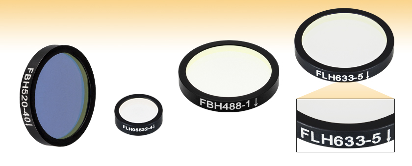
Each filter is housed in a black anodized aluminum ring that is labeled with an arrow indicating the design propagation direction. The ring makes handling easier and enhances the blocking OD by limiting scattering. These filters can be mounted in our extensive line of filter mounts and wheels. As the mounts are not threaded, retaining rings will be required to mount the filters in one of our internally threaded lens tubes. We do not recommend removing the filter from its mount as the risk of damaging the filter is very high.
Use of Computer Generated Hologram in optical testing was pioneered by Wyant and others. The technology is now mature and ready for prime time. We expect it to become more widely used as increasing numbers of aspheres and freeforms are produced. New designs, manufacturing methods, and software are making CGH metrology more accessible by decreasing cost and lead times and by making it easy and quick to align the test and process the data.
The center wavelength of the filter can be tuned slightly (~1 nm over the operating range of the filter) by changing the temperature of the filter. This is primarily due to the slight thermal expansion or contraction of the layers.
Thorlabs expresses LIDT for CW lasers as a linear power density measured in W/cm. In this regime, the LIDT given as a linear power density can be applied to any beam diameter; one does not need to compute an adjusted LIDT to adjust for changes in spot size, as demonstrated by the graph to the right. Average linear power density can be calculated using the equation below.
This adjustment factor results in LIDT values of 0.45 J/cm2 for the BB1-E01 broadband mirror and 1.6 J/cm2 for the Nd:YAG laser line mirror, which are to be compared with the 0.7 J/cm2 maximum energy density of the beam. While the broadband mirror would likely be damaged by the laser, the more specialized laser line mirror is appropriate for use with this system.
Pulsed Nanosecond Laser Example: Scaling for Different WavelengthsSuppose that a pulsed laser system emits 10 ns pulses at 2.5 Hz, each with 100 mJ of energy at 1064 nm in a 16 mm diameter beam (1/e2) that must be attenuated with a neutral density filter. For a Gaussian output, these specifications result in a maximum energy density of 0.1 J/cm2. The damage threshold of an NDUV10A Ø25 mm, OD 1.0, reflective neutral density filter is 0.05 J/cm2 for 10 ns pulses at 355 nm, while the damage threshold of the similar NE10A absorptive filter is 10 J/cm2 for 10 ns pulses at 532 nm. As described on the previous tab, the LIDT value of an optic scales with the square root of the wavelength in the nanosecond pulse regime:
The standard CGH size has been set by the 6”x6” photomask standard. AOM now offers smaller CGHs and mounting hardware at considerably lower cost than the full sized hologram. As production rates for these CGHs increase, the costs will continue to come down.
We reviewed history of the development of CGH application in optical testing. With the trail blazing work of the pioneers, the CGH technology is ready for the prime time. With the development efforts underway, we expect the CGH metrology to be adopted much more widely in the near future.
Soft-coated filters are comprised of dielectric layers sandwiched between optical substrates in a housing as shown in the image to the right. The dielectric layers are often composed of fragile materials such as zinc sulfide, cryolite, or silver. These chemicals react with water, which degrades the performance of the filter, so the shelf life of soft-coated filters is greatly reduced in humid environments. The assembly seals will eventually fail due to the environment, handling, and the construction quality of the filter; the optical performance will rapidly degrade once the seals have failed. Soft-coated filters have a typical lifetime of one to five years in a lab environment owing to these factors.
Please note that we have a buffer built in between the specified damage thresholds online and the tests which we have done, which accommodates variation between batches. Upon request, we can provide individual test information and a testing certificate. The damage analysis will be carried out on a similar optic (customer's optic will not be damaged). Testing may result in additional costs or lead times. Contact Tech Support for more information.
Early CGHs were plotted with digital plotter, and then photo-reduced onto film. In today’s standard, the digital plotters back then had very limited plotting resolution – the plotter Wyant used to make his hologram had 6000 pen positions over 760mm. The photo-reduction process introduces error as well. Also, it took days to fabricate a CGH from plotting to photo-reduction to film development. Early CGH use is therefore limited by these factors.
Notchfilter
Thorlabs' hard-coated bandpass filters reflect out-of-band light with high efficiency. The plot below shows the measured reflectance of an FBH1200-10 hard-coated bandpass filter with a design CWL of 1200 nm and passband FWHM of 10 nm. The blocking region for this filter is specified as ODabs > 5 between the ranges of 200 - 1180 nm and 1220 - 1700 nm.
Thorlabs' hard-coated bandpass filters, which are designed to provide enhanced isolation of key Yb:YAG, Nd:YAG, HeNe, Ar, and diode laser lines, offer excellent (ODavg ≥ 4) suppression in the blocking region while providing ≥85% transmission at the design wavelength (except the 300 nm filter which offers ≥50% transmission). They are available with 12.5 mm or 25 mm outer diameters and are 3.5 mm thick, which allows the Ø25 mm filters to be used as drop-in replacements for our fluorescence emission filters.
4. The system incorporates a pixelated phase sensor from 4D Technologies to perform instantaneous phase shift interferometry, making the test insensitive to vibration.
When an optic is damaged by a continuous wave (CW) laser, it is usually due to the melting of the surface as a result of absorbing the laser's energy or damage to the optical coating (antireflection) [1]. Pulsed lasers with pulse lengths longer than 1 µs can be treated as CW lasers for LIDT discussions.
An engraved arrow on the edge of the filter is used to indicate the recommended direction for the transmission of light through the filter. Orienting the coated side toward the source will reduce unwanted scattering and minimize reflections sent back toward the source. Using the filter in the opposite orientation will not, however, significantly affect the performance of the filter. The plot to the right was made by illuminating the filter with a low intensity broadband light and measuring the transmission as a function of wavelength. This plot shows that the direction of transmission through the filter has very little effect on the intensity and the spectrum of the light transmitted through the filter. The minimal variation between the forward and backward traces is most likely due to a small shift in the incident angle of the light on the filter introduced when the filter was removed, flipped over, and replaced in the jig.
Pastor studied hologram interferometry for testing aspheric surfaces. He first proposed replacing the hologram with a computer generated one in hologram interferometry. In early 70’s, MacGovern and Wyant demonstrated perhaps the earliest use of the CGH in an interferometric test of an asphere. Fercher and his colleagues examined the CGH use in optical testing at about the same time.
The transmission and optical density properties of the hard-coated bandpass filters will vary for far out-of-band wavelengths. The plots below show the variation in transmission and optical density for wavelengths far outside the specified blocking regions of 200 - 379 nm and 401 - 1200 nm for an FBH390-10 hard-coated bandpass filter. The FBH390-10 has a design CWL of 390 nm and a passband FWHM of 10 nm. The blocking region is specified to be ODabs > 5 between the ranges of 200 - 379 nm and 401 - 1200 nm.
The performance of soft-coated filters is limited in the visible wavelengths to approximately 80% transmission if silver is not used and approximately 50% transmission if silver is used in the dielectric stack; the transmission is further limited in the UV. As can be seen in the graphs below, the hard-coated filters have improved transmission in the UV and visible wavelength regimes. The cut-on and cut-off for hard-coated filters is relatively steep compared to the soft-coated filters. The transmission is also much flatter for the hard-coated filters compared with the soft-coated, which is due to the sputtering process used that allows more complicated cavity filter designs to be deposited with high precision and repeatability.
While this rule of thumb provides a general trend, it is not a quantitative analysis of LIDT vs wavelength. In CW applications, for instance, damage scales more strongly with absorption in the coating and substrate, which does not necessarily scale well with wavelength. While the above procedure provides a good rule of thumb for LIDT values, please contact Tech Support if your wavelength is different from the specified LIDT wavelength. If your power density is less than the adjusted LIDT of the optic, then the optic should work for your application.
Low passfilter
CW Laser ExampleSuppose that a CW laser system at 1319 nm produces a 0.5 W Gaussian beam that has a 1/e2 diameter of 10 mm. A naive calculation of the average linear power density of this beam would yield a value of 0.5 W/cm, given by the total power divided by the beam diameter:
As described above, the maximum energy density of a Gaussian beam is about twice the average energy density. So, the maximum energy density of this beam is ~0.7 J/cm2.
In an effort to improve the resolution of the electron microscope, Denis Gabor proposed to record both the amplitude and phase of the image of an object, and then play back the image by illuminating the recorded image with the same or similar reference beam when recording the image. This gave birth to the field of holography. Figures 1 and 2 were taken from his original paper.
If this relatively long-pulse laser emits a Gaussian 12.7 mm diameter beam (1/e2) at 980 nm, then the resulting output has a linear power density of 5.9 W/cm and an energy density of 1.2 x 10⁻⁴ J/cm2 per pulse. This can be compared to the LIDT values for a WPQ10E-980 polymer zero-order quarter-wave plate, which are 5 W/cm for CW radiation at 810 nm and 5 J/cm2 for a 10 ns pulse at 810 nm. As before, the CW LIDT of the optic scales linearly with the laser wavelength, resulting in an adjusted CW value of 6 W/cm at 980 nm. On the other hand, the pulsed LIDT scales with the square root of the laser wavelength and the square root of the pulse duration, resulting in an adjusted value of 55 J/cm2 for a 1 µs pulse at 980 nm. The pulsed LIDT of the optic is significantly greater than the energy density of the laser pulse, so individual pulses will not damage the wave plate. However, the large average linear power density of the laser system may cause thermal damage to the optic, much like a high-power CW beam.
Pulsed lasers with high pulse repetition frequencies (PRF) may behave similarly to CW beams. Unfortunately, this is highly dependent on factors such as absorption and thermal diffusivity, so there is no reliable method for determining when a high PRF laser will damage an optic due to thermal effects. For beams with a high PRF both the average and peak powers must be compared to the equivalent CW power. Additionally, for highly transparent materials, there is little to no drop in the LIDT with increasing PRF.
Nov 8, 2024 — The best Nikon lenses for F-mount: quick list · Best Nikon lens overall: AF-S Nikkor 24-70mm f/2.8E ED VR – buy now · Best Nikon lens for ...
Opticalfilter
In Wyant’s landmark paper, he investigated using the CGH in a Twymann-Green setup for testing an aspheric surface. He developed the theory and validated it with experiments. The advantage of this setup is that the CGH is in the common path of the reference and test beam such that the thickness variation across the film the CGH was recorded on does not affect the measurement accuracy. As the beams pass through the CGH only once, it is easy to filter out the unwanted diffraction orders with a spatial filter at the Fourier plane. He proved that, with the spatial filtering, the wavefront generated by the hologram represent the true continuous target wavefront.
AOM has implemented a design/fabrication process that significantly reduces the lead time. The standard delivery time is 4-5 weeks. It is shortened to 2 weeks with expedition.
However, the maximum power density of a Gaussian beam is about twice the maximum power density of a uniform beam, as shown in the graph to the right. Therefore, a more accurate determination of the maximum linear power density of the system is 1 W/cm.
The alignment of the optic under test is made easy and repeatable by utilizing additional patterns on the same CGH substrate. Light from these patterns is used to guide the position of optomechanical references, which are in turn used to set the alignment of the test. Figure 10 illustrates the concept of a metrology platform which is accurately aligned to the CGH using such dedicated alignment patterns. The optic is placed accurately onto kinematic features on the metrology platform that mate with the datum features on the optic.
These bandpass filters feature durable, hard-coated dielectric coatings on a UV fused silica substrate. The film construction is essentially a modified quarter-wave stack, using interference effects to isolate spectral bands. The dense coating on these filters allows them to be constructed using a single substrate, which yields a stable, long-lasting filter. This coating can withstand the normal cleaning and handling necessary when using any high-quality optical component. Please see the Comparison tab for information about the advantages of hard-coated filters compared to soft-coated filters, such as increased durability and transmission performance.
The Thirty Meter Telescope (TMT) primary mirror consists of nearly 500 segments with 82 different aspheric shapes. Their radii of curvatures need be tightly controlled so the ensemble can act like a single 30 meter mirror. To measure all the segments in a production setting presents challenging requirements. A Fizeau interferometer invented by Burge was built to test the segments. The interferometer consists of a source module, a multiplexed CGH (one for each type of segments), a projection lens and a 1.5m test plate, as illustrated in Figure 8.
The energy density of the beam can be compared to the LIDT values of 1 J/cm2 and 3.5 J/cm2 for a BB1-E01 broadband dielectric mirror and an NB1-K08 Nd:YAG laser line mirror, respectively. Both of these LIDT values, while measured at 355 nm, were determined with a 10 ns pulsed laser at 10 Hz. Therefore, an adjustment must be applied for the shorter pulse duration of the system under consideration. As described on the previous tab, LIDT values in the nanosecond pulse regime scale with the square root of the laser pulse duration:
3. Alignment of the test is achieved using phase fiducial targets – which are reflective CGHs – accurately bonded to the back of the test plate. This system demonstrated 5μm resolution and 25μm alignment accuracy in a manufacturing environment.
The following is a general overview of how laser induced damage thresholds are measured and how the values may be utilized in determining the appropriateness of an optic for a given application. When choosing optics, it is important to understand the Laser Induced Damage Threshold (LIDT) of the optics being used. The LIDT for an optic greatly depends on the type of laser you are using. Continuous wave (CW) lasers typically cause damage from thermal effects (absorption either in the coating or in the substrate). Pulsed lasers, on the other hand, often strip electrons from the lattice structure of an optic before causing thermal damage. Note that the guideline presented here assumes room temperature operation and optics in new condition (i.e., within scratch-dig spec, surface free of contamination, etc.). Because dust or other particles on the surface of an optic can cause damage at lower thresholds, we recommend keeping surfaces clean and free of debris. For more information on cleaning optics, please see our Optics Cleaning tutorial.
Leung, et al investigated writing CGHs with e-beams. The state of the art e-beam machine has resolution of ~5 nm compared to ~0.1 mm plotter resolution in the old days. Direct writing of the CGH shortens the fabrication time from days to hours, and also reduces the number of error sources and allows the use of high quality glass substrate. These capabilities enable practical use of CGH metrology for aspheric and freeform surfaces.
The energy density of your beam should be calculated in terms of J/cm2. The graph to the right shows why expressing the LIDT as an energy density provides the best metric for short pulse sources. In this regime, the LIDT given as an energy density can be applied to any beam diameter; one does not need to compute an adjusted LIDT to adjust for changes in spot size. This calculation assumes a uniform beam intensity profile. You must now adjust this energy density to account for hotspots or other nonuniform intensity profiles and roughly calculate a maximum energy density. For reference a Gaussian beam typically has a maximum energy density that is twice that of the 1/e2 beam.
The innovation featured in this Fizeau interferometer include:1. Each type of segment has its own 3” x 3” CGH that can be easily and accurately inserted into the system using kinematics. The CGH uses multiple patterns including two overlapped patterns that are double etched to provide the reference and testing wavefronts. Other patterns aiding the alignments are included as well.2. A full-sized test plate, supported 13 meters from the CGH system is common for all the segments.3. Alignment of the test is achieved using phase fiducial targets – which are reflective CGHs – accurately bonded to the back of the test plate. This system demonstrated 5μm resolution and 25μm alignment accuracy in a manufacturing environment.4. The system incorporates a pixelated phase sensor from 4D Technologies to perform instantaneous phase shift interferometry, making the test insensitive to vibration.
Computer Generated Holograms are widely used for measuring surface figures of aspheres and freeforms. The CGH test is accurate, versatile, quick and powerful. This paper reviews the historic development of the technology. It started with the invention of holography by Denis Gabor, followed by the invention of the computer generated hologram by Adolf Lohman. Pioneering work on the CGH use in optical testing is reviewed including: Jim Wyant demonstrated the CGH application in optical testing; Steve Arnold and colleagues developed writing technology using ebeam machines; Alex Poleshchuk et al built a circular laser writers dedicated to writing the symmetric CGHs; Jim Burge invented many innovative uses of the CGH.
The laminated structure of the soft-coated filters means that changes in temperature can have a drastic effect on the optical performance of the filter. The dielectric stack, epoxy, optical substrate, absorption glass, and housing may all have different coefficients of thermal expansion. This may result in the shape of the filter changing in unexpected ways with changes in temperature.
The reason is that the image circle produced by a full-frame lens is more than large enough to fill the area taken up by your camera's crop sensor.
The pulse length must now be compensated for. The longer the pulse duration, the more energy the optic can handle. For pulse widths between 1 - 100 ns, an approximation is as follows:
MATLABbandpass
[1] R. M. Wood, Optics and Laser Tech. 29, 517 (1998).[2] Roger M. Wood, Laser-Induced Damage of Optical Materials (Institute of Physics Publishing, Philadelphia, PA, 2003).[3] C. W. Carr et al., Phys. Rev. Lett. 91, 127402 (2003).[4] N. Bloembergen, Appl. Opt. 12, 661 (1973).
Hard-coated filters are produced by sputtering dielectric layers onto a glass substrate; the dielectric filter stack can be exposed to the environment, as shown below to the right, without degradation of performance owing to the material being more environmentally stable than what is used for the soft-coated filters. The hard-coated filters are thinner than soft-coated filters, which allows them to be more easily incorporated into space-limited applications. The sputtering process is automated, highly repeatable, and results in a transmitted wavefront error value that is close to that of the uncoated optic.
LIDT in linear power density vs. pulse length and spot size. For long pulses to CW, linear power density becomes a constant with spot size. This graph was obtained from [1].
The adjusted LIDT value of 350 W/cm x (1319 nm / 1550 nm) = 298 W/cm is significantly higher than the calculated maximum linear power density of the laser system, so it would be safe to use this doublet lens for this application.
(a) Original micrograph, 1.4mm diameter. (b) Micrograph, directly photographed through the same optical system which is used for the reconstruction (d). AP. 0.04. (c) interference diagram, obtained by projecting the micrograph on a photographic plate with a beam diverging from a point focus. The letters have become illegible by diffraction. (d) Reconstruction of the original by optical synthesis from the diagram on the left. To be compared with (b). The letters have again become legible (Taken from Gabor’s original paper)
In order to illustrate the process of determining whether a given laser system will damage an optic, a number of example calculations of laser induced damage threshold are given below. For assistance with performing similar calculations, we provide a spreadsheet calculator that can be downloaded by clicking the button to the right. To use the calculator, enter the specified LIDT value of the optic under consideration and the relevant parameters of your laser system in the green boxes. The spreadsheet will then calculate a linear power density for CW and pulsed systems, as well as an energy density value for pulsed systems. These values are used to calculate adjusted, scaled LIDT values for the optics based on accepted scaling laws. This calculator assumes a Gaussian beam profile, so a correction factor must be introduced for other beam shapes (uniform, etc.). The LIDT scaling laws are determined from empirical relationships; their accuracy is not guaranteed. Remember that absorption by optics or coatings can significantly reduce LIDT in some spectral regions. These LIDT values are not valid for ultrashort pulses less than one nanosecond in duration.
In a following paper, Jim Wyant further investigated the error sources of the CGH test and verified it with the experiment results. He realized the CGH pattern is just a binary representation of the real interferogram formed by the ideal object and reference wavefront, therefore, he departed away from Lohmann’s and Lee’s encoding scheme. All the CGHs now used in testing aspheres/freeforms are generated this way.
Now compare the maximum power density to that which is specified as the LIDT for the optic. If the optic was tested at a wavelength other than your operating wavelength, the damage threshold must be scaled appropriately. A good rule of thumb is that the damage threshold has a linear relationship with wavelength such that as you move to shorter wavelengths, the damage threshold decreases (i.e., a LIDT of 10 W/cm at 1310 nm scales to 5 W/cm at 655 nm):
bandpassfilter中文
Thorlabs' Visible Bandpass Filter Kits each contain 10 mounted hard-coated bandpass filters that can be used to transmit a well-defined wavelength band in the visible, while rejecting other unwanted radiation. Each filter is mounted in an unthreaded Ø25.0 mm black-anodized aluminum ring that can be placed into our selection of Ø1" lens tubes and filter mounts using retaining rings. The filter kits come in a convenient plastic box for storage and transportation purposes.
The calculation above assumes a uniform beam intensity profile. You must now consider hotspots in the beam or other non-uniform intensity profiles and roughly calculate a maximum power density. For reference, a Gaussian beam typically has a maximum power density that is twice that of the uniform beam (see lower right).
Soft-coated and hard-coated filters are commonly sold in the optics industry. Soft-coated filters suffer from poor temperature stability, low transmission, high optical scatter, and a short shelf life owing to their laminate structure of chemically reactive layers. The hard-coated filters do not suffer from these shortcomings as they are formed of chemically inert layers on an optical substrate via a high-energy sputtering technique.
With advent of computers, Adolf Lohmann realized that an object does not have to exist to record a hologram; you can calculate the light field from the object and then plot the “hologram.” To plot both the amplitude and phase of a light field, he proposed an encoding scheme called “detour phase”. He defined a unit recoding area as a cell which has an opening, the size and position of which represent the amplitude and phase, respectively. The scheme is illustrated in Figure 3. An early CGH pattern and the re-constructed image is shown in Figure 4.
After the basic principles of the CGH metrology were established and highly accurate and efficient fabrication technology was developed, innovative application of CGH metrology has solved challenging problems. In this section, we present an example test demonstrating the power of the CGHs in overcoming practical metrology challenges.
Pulsed Microsecond Laser ExampleConsider a laser system that produces 1 µs pulses, each containing 150 µJ of energy at a repetition rate of 50 kHz, resulting in a relatively high duty cycle of 5%. This system falls somewhere between the regimes of CW and pulsed laser induced damage, and could potentially damage an optic by mechanisms associated with either regime. As a result, both CW and pulsed LIDT values must be compared to the properties of the laser system to ensure safe operation.
Interference between homocentric illuminating wave and the secondary wave emitted by a small object. (Taken from Gabor’s original paper)
The phenomenon in which electromagnetic waves, such as light waves, vibrate in a preferred plane or planes; or the process of confining the vibrations to ...
This scaling gives adjusted LIDT values of 0.08 J/cm2 for the reflective filter and 14 J/cm2 for the absorptive filter. In this case, the absorptive filter is the best choice in order to avoid optical damage.
An AC127-030-C achromatic doublet lens has a specified CW LIDT of 350 W/cm, as tested at 1550 nm. CW damage threshold values typically scale directly with the wavelength of the laser source, so this yields an adjusted LIDT value:
As previously stated, pulsed lasers typically induce a different type of damage to the optic than CW lasers. Pulsed lasers often do not heat the optic enough to damage it; instead, pulsed lasers produce strong electric fields capable of inducing dielectric breakdown in the material. Unfortunately, it can be very difficult to compare the LIDT specification of an optic to your laser. There are multiple regimes in which a pulsed laser can damage an optic and this is based on the laser's pulse length. The highlighted columns in the table below outline the relevant pulse lengths for our specified LIDT values.
This system was set up at Arizona Optical Systems for a prototype 1.3-m TMT mirror segment, demonstrating complete alignment within a few minutes, achieving measurement repeatability of 1 nm rms.


 Ms.Cici
 8618319014500