
Complete German Safety Goggles Set - lenses deutsch
By examining the numerical aperture equation, it is apparent that refractive index is the limiting factor in achieving numerical apertures greater than 1.0. Therefore, in order to obtain higher working numerical apertures, the refractive index of the medium between the front lens of the objective and the specimen must be increased. Microscope objectives are now available that allow imaging in alternative media such as water (refractive index = 1.33), glycerin (refractive index = 1.47), and immersion oil (refractive index = 1.51). Care should be used with these objectives to prevent unwanted artifacts that will arise when an objective is used with a different immersion medium than it was designed for. We suggest that microscopists never use objectives designed for oil immersion with either glycerin or water, although several newer objectives have recently been introduced that will work with multiple media. You should check with the manufacturer if there are any doubts.
Nonetheless, those of us at SURF collaborated with industry to develop different ways that NIST could help. We worked with large companies and industry consortia to develop instrumentation and tests for the new optics, both in terms of in their performance and their resistance to the possibly unfriendly environments they would experience within the vacuum systems that EUV lithography requires.
Numerical aperture of4xObjective lens
The resolution of a microscope objective is defined as the smallest distance between two points on a specimen that can still be distinguished as two separate entities. Resolution is a somewhat subjective value in microscopy because at high magnification, an image may appear unsharp but still be resolved to the maximum ability of the objective. Numerical aperture determines the resolving power of an objective, but the total resolution of a microscope system is also dependent upon the numerical aperture of the substage condenser. The higher the numerical aperture of the total system, the better the resolution.
In practice, however, it is difficult to achieve numerical aperture values above 0.95 with dry objectives. Figure 2 illustrates a series of light cones derived from objectives of varying focal length and numerical aperture. As the light cones change, the angle µ increases from 7° in Figure 2(a) to 60° in Figure 2(c), with a resulting increase in the numerical aperture from 0.12 to 0.87, nearing the limit when air is the imaging medium.
Diffraction at Circular Apertures. If a light beam (for example a laser beam) encounters some aperture which transmits the light in some regions and blocks it ...
Correct alignment of the microscope optical system is also of paramount importance to ensure maximum resolution. The substage condenser must be matched to the objective with respect to numerical aperture and adjustment of the aperture iris diaphragm for accurate light cone formation. The wavelength spectrum of light used to image a specimen is also a determining factor in resolution. Shorter wavelengths are capable of resolving details to a greater degree than are the longer wavelengths. There are several equations that have been derived to express the relationship between numerical aperture, wavelength, and resolution:
An important concept to understand in image formation is the nature of diffracted light rays intercepted by the objective. Only in cases where the higher (1st, 2nd, 3rd, etc.) orders of diffracted rays are captured, can interference work to recreate the image in the intermediate image plane of the objective. When only the zeroth order rays are captured, it is virtually impossible to reconstitute a recognizable image of the specimen. When 1st order light rays are added to the zeroth order rays, the image becomes more coherent, but it is still lacking in sufficient detail. It is only when higher order rays are recombined, that the image will represent the true architecture of the specimen. This is the basis for the necessity of large numerical apertures (and subsequent smaller Airy disks) to achieve high-resolution images with an optical microscope.
In the early 1970s, NASA used SURF I to calibrate space instruments that study the Sun. These calibrations ensured that the measurements would be accurate once the instruments were launched into space. Years later special telescopes calibrated at updated versions of SURF produced wonderful images of the solar corona at several EUV wavelengths. These EUV “pictures” helped scientists build a temperature map of the Sun.
The angle µ is one-half the angular aperture (A) and is related to the numerical aperture through the following equation:
Their magnification factors vary between 5X and 30X with the most commonly used eyepieces having a value of 10X-15X. Total visual magnification of the ...
At first, manufacturers used visible light to etch circuit patterns onto chips. The first commercially available microprocessor, the Intel 4004, came out in 1971 and had about 1,000 transistors per square centimeter. Each transistor, in turn, was made with parts having dimensions as small as about 10 micrometers, or 10 millionths of a meter.
Feb 16, 2023 — Lenses with lower magnification (eg 4x, 10x) have a greater depth of field than lenses with higher magnification (eg 40x, 60x, 100x). Depth of ...
Numerical aperture ofoil immersionlens
When the microscope is in perfect alignment and has the objectives appropriately matched with the substage condenser, then we can substitute the numerical aperture of the objective into equations (1) and (2), with the added result that equation (3) reduces to equation (2). An important fact to note is that magnification does not appear as a factor in any of these equations, because only numerical aperture and wavelength of the illuminating light determine specimen resolution. As we have mentioned (and can be seen in the equations) the wavelength of light is an important factor in the resolution of a microscope. Shorter wavelengths yield higher resolution (lower values for R) and visa versa. The greatest resolving power in optical microscopy is realized with near-ultraviolet light, the shortest effective imaging wavelength. Near-ultraviolet light is followed by blue, then green, and finally red light in the ability to resolve specimen detail. Under most circumstances, microscopists use white light generated by a tungsten-halogen bulb to illuminate the specimen. The visible light spectrum is centered at about 550 nanometers, the dominant wavelength for green light (our eyes are most sensitive to green light). It is this wavelength that was used to calculate resolution values in Table 2. The numerical aperture value is also important in these equations and higher numerical apertures will also produce higher resolution, as is evident in Table 2. The effect of the wavelength of light on resolution, at a fixed numerical aperture (0.95), is listed in Table 3.
where n is the refractive index of the imaging medium between the front lens of the objective and the specimen cover glass, a value that ranges from 1.00 for air to 1.51 for specialized immersion oils. Many authors substitute the variable α for µ in the numerical aperture equation. From this equation it is obvious that when the imaging medium is air (with a refractive index, n = 1.0), then the numerical aperture is dependent only upon the angle µ whose maximum value is 90°. The sin of the angle µ, therefore, has a maximum value of 1.0 (sin(90°) = 1), which is the theoretical maximum numerical aperture of a lens operating with air as the imaging medium (using "dry" microscope objectives).
Where does the National Institute of Standards and Technology (NIST) come into play here? NIST was an early collaborator with those in the microelectronics industry who saw that it might be possible to use extreme ultraviolet (EUV) light to create electronic devices with smaller features like those we have today. This challenging goal was realized after a long, hard struggle.
Numerical aperture of 100x objective lensformula
Laser Substrates provides software solutions to generate web certified mail and tax forms for property management & accounting software.
We privately experienced occasional doubts about whether the industry efforts would ultimately be successful. But despite the challenges, we continued to collaborate with the industry partners to overcome the many hurdles. We were glad that our contributions in the struggle to limit the degrading effect of the EUV light on the reflective optics, one of many significant problems, helped remove this barrier to progress.
Numerical aperture of10xobjective lens
This feature of increasing numerical aperture across an increasing optical correction factor in a series of objectives of similar magnification holds true throughout the range of magnifications as shown in Table 1. Most manufacturers strive to ensure that their objectives have the highest correction and numerical aperture that is possible for each class of objective.
Careful positioning of the substage condenser aperture diaphragm is also critical to the control of numerical aperture and indiscriminate use of this diaphragm can lead to image degradation (as discussed in the section on substage condensers). Other factors, such as contrast and the efficiency of illumination, are also key elements that affect image resolution.
The smaller the Airy disks projected by an objective in forming the image, the more detail of the specimen that becomes discernible. Objectives of higher correction (fluorites and apochromats) produce smaller Airy disks than do objectives of lower correction. In a similar manner, objectives that have a higher numerical aperture are also capable of producing smaller Airy disks. This is the primary reason that objectives of high numerical aperture and total correction for optical aberration can distinguish finer detail in the specimen.
Having demonstrated to the world the usefulness of synchrotron radiation, NBS researchers created the first dedicated synchrotron ultraviolet radiation facility, or SURF I, to use this radiation to perform many interesting experiments and establish a new basis for calibrating various light sources and light detectors. From this unique beginning, the world has now fully invested in the use of synchrotron radiation, with over 50 synchrotron light facilities operating worldwide.
Figure 3(a) illustrates a hypothetical Airy disk that essentially consists of a diffraction pattern containing a central maximum (typically termed a zeroth order maximum) surrounded by concentric 1st, 2nd, 3rd, etc., order maxima of sequentially decreasing brightness that make up the intensity distribution. Two Airy disks and their intensity distributions at the limit of optical resolution are illustrated in Figure 3(b). In this part of the figure, the separation between the two disks exceeds their radii, and they are resolvable. The limit at which two Airy disks can be resolved into separate entities is often called the Rayleigh criterion. Figure 3(c) shows two Airy disks and their intensity distributions in a situation where the center-to-center distance between the zeroth order maxima is less than the width of these maxima, and the two disks are not individually resolvable by the Rayleigh criterion.
Classical Fresnel Lens Listing. The first National Lighthouse Lens Survey was released in 2001 at the Sixth Maritime Heritage Conference in Wilmington, N.C. It ...
Many such EUV measurements now being made by NASA and NOAA have more than purely scientific importance. They can serve to help in designing early warning systems for solar storms that could knock out GPS and communication links. It takes an average of eight minutes and 20 seconds for light from the Sun to reach Earth, but it takes a few hours to a few days for dangerous particles to arrive. So, if we get an early warning of a solar storm, then we could have time to prepare for it.
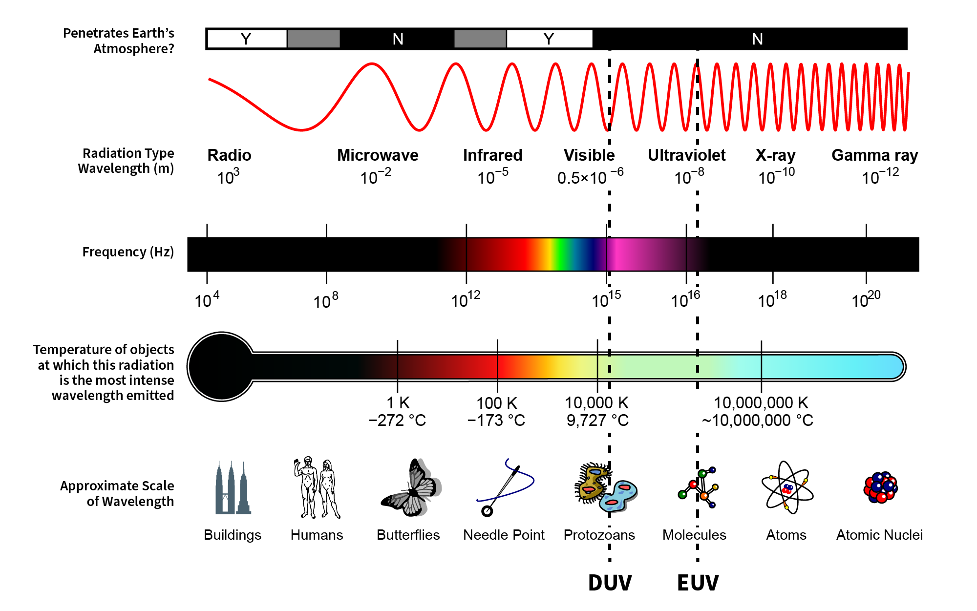
Around the same time, several forward-looking researchers in the microelectronics industry thought that using EUV light, which has a much shorter wavelength (13.5 nm, to be exact), would be the key technology to allow the industry to continue marching forward under Moore’s Law.
Particle accelerators, such as the original electron synchrotron at the National Bureau of Standards (NBS, the agency that later was renamed NIST), were first developed about 80 years ago to study what was going on in the cores of atoms, known as nuclei. All such devices accelerate charged particles, a process that produces light (i.e., electromagnetic radiation), at first considered an unwanted byproduct. Back in 1961, scientists at NBS found that the light from their synchrotron, rather than being an unwanted source of energy loss, could be used to do some interesting experiments on atoms. The result was a seminal 1963 publication that showed how this now-dubbed “synchrotron radiation” could be used to uncover some never-before-observed features in how helium and other rare gases respond to light in the far ultraviolet region of the spectrum.
Most objectives in the magnification range between 60x and 100x (and higher) are designed for use with immersion oil. By examining the numerical aperture equation above, we find that the highest theoretical numerical aperture obtainable with immersion oil is 1.51 (when sin (µ) = 1). In practice, however, most oil immersion objectives have a maximum numerical aperture of 1.4, with the most common numerical apertures ranging from 1.0 to 1.35.
The use of EUV for lithography would require a whole new optical technology: a new type of UV light source and a new type of optics. EUV required the use of “reflective” instead of the usual “transmissive” optics (that is, mirrors rather than lenses) because no material transmits light at the EUV wavelength. Also needed was a new tool environment. Instead of the tool operating at atmospheric pressure, where EUV is readily absorbed, the system required a high-vacuum environment. The job was much harder than first imagined. Many scientists and engineers familiar with microelectronics manufacturing thought it to be next to impossible to mass-produce chips with EUV.
LED lighting differs from traditional incandescent and fluorescent lighting in several ways, with the main difference being efficiency. LED lights use 25% to 80 ...
The numerical aperture of an objective is also dependent, to a certain degree, upon the amount of correction for optical aberration. Highly corrected objectives tend to have much larger numerical apertures for the respective magnification as illustrated in Table 1 below. If we take a series of typical 10x objectives as an example, we see that for flat-field corrected plan objectives, numerical aperture increases correspond to correction for chromatic and spherical aberration: plan achromat, N.A. = 0.25; plan fluorite, N.A. = 0.30; and plan apochromat, N.A. = 0.45.
Secure .gov websites use HTTPS A lock ( Lock A locked padlock ) or https:// means you’ve safely connected to the .gov website. Share sensitive information only on official, secure websites.
Light waves can be imagined as waterlike ripples, with regularly repeating peaks and valleys. Just like in water waves, light’s wavelength is defined as the distance between two wave peaks. The shorter the wavelength, the closer the peaks are to each other, and the finer the patterns you can etch on a chip. In short, shorter wavelengths mean smaller transistors, and more electronic devices on the same-sized chip.
Where R is resolution (the smallest resolvable distance between two objects), NA equals numerical aperture, λ equals wavelength, NA(obj) equals the objective numerical aperture, and NA(Cond) is the condenser numerical aperture. Notice that equation (1) and (2) differ by the multiplication factor, which is 0.5 for equation (1) and 0.61 for equation (2). These equations are based upon a number of factors (including a variety of theoretical calculations made by optical physicists) to account for the behavior of objectives and condensers, and should not be considered an absolute value of any one general physical law. In some instances, such as confocal and fluorescence microscopy, the resolution may actually exceed the limits placed by any one of these three equations. Other factors, such as low specimen contrast and improper illumination may serve to lower resolution and, more often than not, the real-world maximum value of R (about 0.25 µm using a mid-spectrum wavelength of 550 nanometers) and a numerical aperture of 1.35 to 1.40 are not realized in practice. Table 2 provides a list resolution (R) and numerical aperture (NA) by objective magnification and correction.
Great article. My curiosity drew me into this article because it was written for a novice like myself. I will share this with geeky friends who I know will appreciate the work you folks do as you advance our knowledge base and create all sort of cool things.
In day-to-day routine observations, most microscopists do not attempt to achieve the highest resolution image possible with their equipment. It is only under specialized circumstances, such as high-magnification brightfield, fluorescence, DIC, and confocal microscopy that we strive to reach the limits of the microscope. In most uses of the microscope, it is not necessary to use objectives of high numerical aperture because the specimen is readily resolved with use of lower numerical aperture objectives. This is particularly important because high numerical aperture and high magnification are accompanied by the disadvantages of very shallow depth of field (this refers to good focus in the area just below or just above the area being examined) and short working distance. Thus, in specimens where resolution is less critical and magnifications can be lower, it is better to use lower magnification objectives of modest numerical aperture in order to yield images with more working distance and more depth of field.
Numerical aperture of40xobjective lens
I am excited reading how solar energy is being used for peaceful means. I am Reiki Therspist using Universal Energy Field for healing and wellness including long distance healing. Consider exploring Sound aspect of Universal Energy. The “OM” resonates with great cosmic vibrations so subtle all-encompassing that everything seen and unseen is filled with it. Consider exploring using Universal Energy Field for health and wellness into mainstream practice as shown by small samples of Reiki and Tuning Fork modalities. Thank You
Numerical aperture ofcondenserlens
Michael W. Davidson - National High Magnetic Field Laboratory, 1800 East Paul Dirac Dr., The Florida State University, Tallahassee, Florida, 32310.
Numerical aperture of objective lens
Interest is growing in EUV and UV radiation as researchers continue to find more applications for EUV/UV light sources and optics. NIST’s research in the EUV connects some of the biggest things in the solar system to the smallest, from studies of the Sun itself to the manufacture of the tiny transistors in a cell phone. It’s great to have had the opportunity to collaborate with everyone from semiconductor manufacturers to astronomers on these projects, and we look forward to seeing and enabling future developments in EUV and UV applications.
The numerical aperture of a microscope objective is a measure of its ability to gather light and resolve fine specimen detail at a fixed object distance. Image-forming light waves pass through the specimen and enter the objective in an inverted cone as illustrated in Figure 1. A longitudinal slice of this cone of light shows the angular aperture, a value that is determined by the focal length of the objective.
In 2019, after decades of effort, manufacturers used a new technology to create smartphones with individual circuit features as small as 7 nanometers (nm), or billionths of a meter, enabling them to cram 8.5 billion electronic devices known as transistors on a single small chip. Fitting more transistors in the same small space means faster, more powerful smartphones, computers and other electronic devices.
For a normal, relaxed eye, a magnifying glass produces an angular magnification of 4.0. What is the largest magnification possible with this magnifying glass?
Tom Lucatorto received his Ph.D. from Columbia in 1968 for work on atomic structure. He has over 125 publications and four patents, is a Fellow of the American Physical Society, and is the recipient of the Department of Commerce Silver Medal in 1980 and in 2013. He has been the leader of the Ultraviolet Radiation Group at NIST for the last three decades. That group’s role is to provide accurate measurements in the spectral range from 4 nm to 400 nm, which include calibrations of all NASA and NOAA’s solar UV instruments and other optics used in astronomy, fusion plasma diagnostics, laser development and EUV lithography.
Figure 4 illustrates the effect of numerical aperture on the size of Airy disks imaged with a series of hypothetical objectives of the same focal length, but differing numerical apertures. With small numerical apertures, the Airy disk size is large, as shown in Figure 4(a). As the numerical aperture and light cone angle of an objective increases however, the size of the Airy disk decreases as illustrated in Figure 4(b) and Figure 4(c). The resulting image at the eyepiece diaphragm level is actually a mosaic of Airy disks which we perceive as light and dark. Where two disks are too close together so that their central spots overlap considerably, the two details represented by these overlapping disks are not resolved or separated and thus appear as one, as illustrated above in Figure 3.
Thus, the chip manufacturers started to use light with shorter and shorter wavelengths to keep up with Moore’s law. In about 1990 they reached a deep ultraviolet (DUV) wavelength of 193 nm, which was as far as they could go using conventional optical technology.
The Sun is constantly bombarding NASA and NOAA space satellites with radiation, including EUV light. This EUV radiation degrades important satellite components, such as optical filters. With its EUV light source, NIST can simulate five years of Sun exposure in two weeks, providing important data for protecting satellites and their delicate components.
Numerical aperture ofmicroscope formula
Meanwhile, in the 1980s, electronic chipmakers began to worry about how to keep up with “Moore’s law,” the roadmap that compels the microcircuit industry to constantly strive to double the number of transistors on a chip every two years or so. Making computer chips starts out with creating a pattern on a wafer of silicon in a process known as lithography (Greek for “to draw on a stone”). This is done by shining a pattern of light on a thin coating of a light-sensitive material atop a silicon wafer. The light-sensitive material is then developed to form an intricate circuit pattern.
Would never buy full price. Was in an AE store in a major east coast city the other day to return a pair of Higgins mills with terrible leather ...
Optum Perks and Healthgrades are subsidiaries of RVO Health. Location. CVS Pharmacy. 620 W Pike St, Lawrenceville, GA 30046. Get Directions.
The transmitted beam becomes largely p-polarized while the reflected beam is s-polarized.
As we have seen in NASA’s and NOAA’s study of the Sun, the importance of EUV light goes beyond chip manufacture — it includes being an essential messenger from outer space.
Official websites use .gov A .gov website belongs to an official government organization in the United States.
Charlie Tarrio received his BS from Bates College in Lewiston, Maine, and Ph.D. in physics from the University of Virginia. He has been at NIST since 1991 developing at-wavelength EUV metrology and studying properties and contamination of EUV optics.
Visitors are invited to explore changes in numerical aperture with changes in µ, using our interactive Java tutorial that investigates how numerical aperture and magnification are related to the angular aperture of an objective.
When light from the various points of a specimen passes through the objective and is reconstituted as an image, the various points of the specimen appear in the image as small patterns (not points) known as Airy patterns. This phenomenon is caused by diffraction or scattering of the light as it passes through the minute parts and spaces in the specimen and the circular back aperture of the objective. The central maximum of the Airy patterns is often referred to as an Airy disk, which is defined as the region enclosed by the first minimum of the Airy pattern and contains 84 percent of the luminous energy. These Airy disks consist of small concentric light and dark circles as illustrated in Figure 3. This figure shows Airy disks and their intensity distributions as a function of separation distance.


 Ms.Cici
 8618319014500