
Comparison of a Scheimpflug imaging with other screening ... - scheimpflug image
Knowledge of the focal length of a lens is vital in the construction of all optical instruments, from spectacles to large astronomical telescopes. The range of possible focal lengths is very large, from a few milli- metres for the objective lens of a microscope to 20 m in a large telescope. Several simple methods are described because they all illustrate different aspects of the lens formula.
FOV tofocal length
Copyright © 2016-2024 Bytronic.com. All rights reserved. Registered in England and Wales No. 03348154. VAT Reg GB695393384.
A wider FOV covers more space but sacrifices some detail, while a narrower FOV captures more detail but focuses on a smaller area.
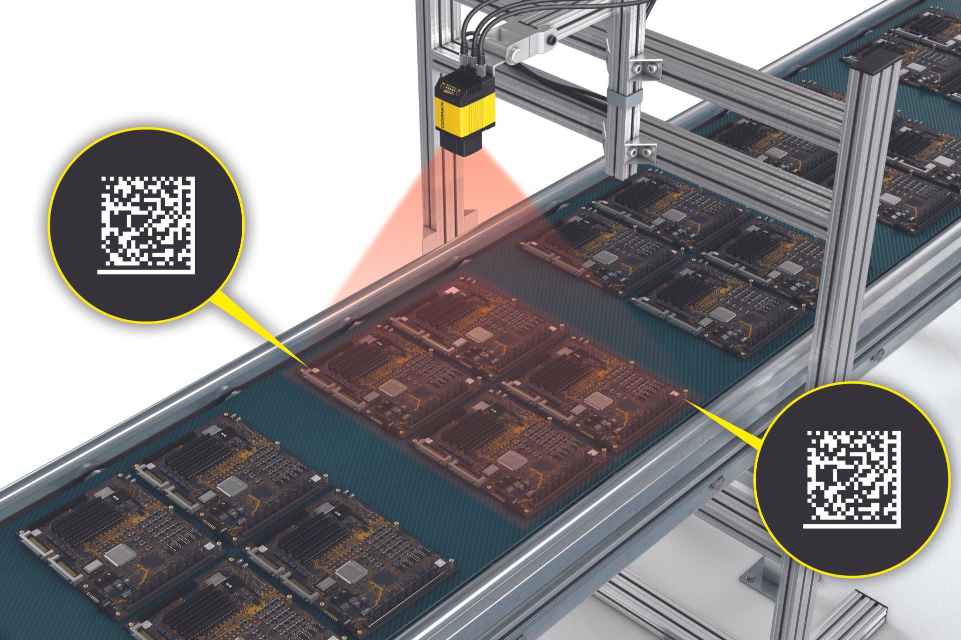
Field of view plays a crucial role in industrial automation, where vision systems are used for quality control, inspections, and robotics.
Focal length formulafor concavelens
Bytronic Vision Intelligence has decades of experience, through hundreds of vision applications. If you have a vision application, contact us and we can work with you to find a solution.
So far all the methods have been for convex lenses where a real image can be produced. We will now consider some methods for concave lenses.(i) An auxiliary convex lens is used, in contact with the concave lens. It must be of greater power than the concave lens with one of its faces having the same radius of curvature as one of the faces of the concave lens. The focal length of the combination is then given by 1/F = 1/f + 1/f'where the focal length of the convex lens f' can be found by the methods described above.(ii) A convex lens of greater power is used to give a virtual object for the concave lens (Figure 4).
Focal length formulafor convexlens
To make things easier, Cognex offers a handy tool called the Lens Advisor. It’s an interactive tool that helps you select the right lens and field of view. Just enter your camera and application-specific parameters, and it will provide recommendations tailored to your needs.
Focal length formulafor mirror
Having the right FOV ensures that you capture important features and defects with enough detail. This is crucial for making accurate decisions in real-time production environments.
In this blog post, we’ll break down the importance of field of view, explain its relevance in industrial automation, and explore how to choose the right field of view for your application using insights from the Cognex Lens Advisor tool.
Focaldistance vsfocal length
For a given separation of the object and screen it will be found that there are two positions where a clearly focused image can be formed (Figure 2). By the principle or reversibility these must be symmetrical between 0 and I. Using the notation shown: d = u+v and a = v uTherefore: u = [d a]/2 and v = [d + a]/2Substituting in the lens equation gives:2/[d a] + 2/[d + a] = 1/f and hence f = [d2 a2]/4d(v) The minimum distance methodThis more mathematical method derives from the fact that there is a minimum separation for object and image for a given lens. This can be shown if u + v is plotted against either u or v. A minimum is formed (shown by Figure 3) and this can be shown to occur at the point where u = v = 2f and u + v = 4f, that is, the minimum separation for object and image is 4f.
Field of view refers to the area that your camera lens can capture in a scene or object. It’s like the camera’s viewing angle.
Focal length formula
When it comes to vision systems, understanding the concept of field of view (FOV) is essential. It determines what your camera can see and affects how you analyse images in machine vision applications.
focallength中文

By understanding the relationship between FOVand your application requirements, you can optimise your vision system. This ensures accurate data capture, minimises errors, and boosts overall system performance and productivity.
(i) The focusing method A rough guide to the focal length of a lens can be obtained by focusing light from a distant object, such as the Sun, on to a screen. (ii) The graphical methodA graph of 1/u against 1/v can be plotted and the focal length (f) found from this. The point where the line intersects either axis is 1/f.
The plane mirror methodThe lens is placed on the mirror as shown in Figure 1, and the object is moved until object and image coincide. This point is the principal focus, since light from it will emerge parallel from the lens and so be reflected back along its original path when it strikes the mirror. The object can be either a pin or a point source.Since R = 2f for a lens of glass of refractive index 1.5 placed in air, the value of f can be found.


 Ms.Cici
 8618319014500