
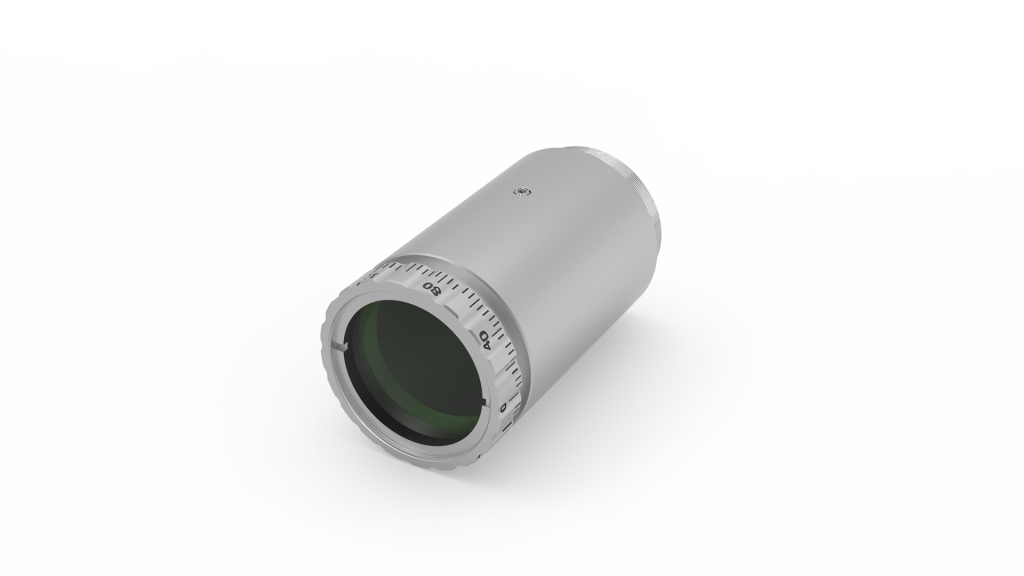
Collimated Beam Measurement System - collimating device
Galvanometer Motor/Mirror AssemblyThe system consists of a galvanometer-based scanning motor with a mirror mounted on the shaft and a detector that provides positional feedback to the control board. The moving magnet design for the QS and QG series of galvanometer motors were chosen over a stationary magnet and rotating coil design in order to provide the fastest response times and the highest system resonant frequency. The position of the mirror is encoded using an optical or capacitive sensing system located inside of the motor housing.
The CBLS3F Power and Command Cable set can be used to connect the GPWR15 power supply to the QG4/5, QS15/20/30/45, SS, or SP series galvo scanners. The power cable has a three pin connector on one end and three bare wires for soldering to the GPWR15 power supply on the other end. The command cable has a four pin connector on one end and three bare wires for soldering to a user-supplied controller on the other end.
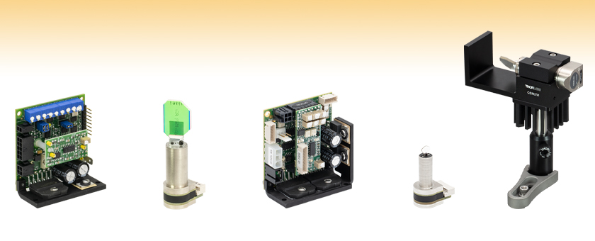
Each system includes a galvanometer scan head, driver board, and drive cable. A compatible GPWR15 Power Supply and CBLS3F Command and Power Cables can be purchased separately below. A compatible QSM3(/M) mount for safe and easy integration into optical setups is also sold separately below.
For orders where a large quantity of an item is purchased and the delivery of that item is scheduled with our production (i.e., not taken directly from inventory), Thorlabs passes on to the customer the cost savings associated with planned production of high volumes of that item. Since the volume and planned production are key to realizing the cost savings, we ask that you contact us to obtain volume pricing.
Both drivers feature proportional-integral-derivative (PID) servo driver circuits with advanced current damping for high performance. The drivers incorporate low-noise components to maximize the signal-to-noise ratio for better accuracy and low-drift components to reduce the effects of temperature variation. A notch filter is selected and tuned for each unique mirror-galvo combination to maximize system bandwidth for faster, more accurate scanning. These systems are ideal for use in applications including step-and-hold positioning, vector positioning (e.g., laser marking), and raster positioning (printing or scanning laser microscopy).
Due to the large angular acceleration of the rotation shaft, the size, shape, and inertia of the mirrors become significant factors in the design of high-performance galvanometer systems. Furthermore, the mirror must remain rigid (flat) even when subjected to large accelerations. All these factors have been precisely balanced in our systems in order to match the characteristics of the motor and maximize performance.
Each system includes a galvanometer scan head, driver board, and drive cable. A compatible GPWR15 Power Supply and CBLS3F Command and Power Cables, or GPS011 series Linear Power Supply and CBLS3P Command and Power Cables can be purchased separately below. A compatible QSM2(/M) mount for safe and easy integration into optical setups is also sold separately below.
Each system includes a galvanometer scan head, driver board, and drive cable. A compatible GPWR15 Power Supply and CBLS2F Command and Power Cables, or GPS011 series Linear Power Supply and CBLS2P Command and Power Cables can be purchased separately below. A compatible QSM1(/M) mount for safe and easy integration into optical setups is also sold separately below.
Altechna’s beam expanders are assembled using one diverging and one converging lens. As there is no focal point inside of the beam expander, it can be used with high power laser sources. Special treatment of lenses and mechanics is performed for UV application to improve lifetime and LIDT of the expander. Standard magnifications are from 1.1x to 5x. Beam expanders for any wavelengths between 266 – 1064 nm are available upon request.
Each system includes a galvanometer scan head, driver board, and drive cable. A compatible GPWR15 Power Supply and CBLS2F Command and Power Cables, or GPS011 series Linear Power Supply and CBLS2P Command and Power Cables can be purchased separately below. A compatible QSM1(/M) mount for safe and easy integration into optical setups is also sold separately below.
A plastic insulating shim (0.002" thick) is included with QSM3(/M) mounts to protect the capacitive position detector from electrical noise. It is recommended that users wrap the shim around the galvo prior to mounting for electrical isolation.
Each system includes a galvanometer scan head, driver board, and drive cable. A compatible GPWR15 Power Supply and CBLS3F Command and Power Cables, or GPS011 series Linear Power Supply and CBLS3P Command and Power Cables can be purchased separately below. A compatible QSM4(/M) mount for safe and easy integration into optical setups is also sold separately below.
System OperationThe servo driver must be connected to a DC power supply, the galvanometer motor, and an input command voltage source (the monitoring connection is optional). For continuous scanning applications, a function generator with a sine wave output is sufficient for scanning the mirror over its entire range. For more complex scanning patterns, a programmable voltage source such as a DAQ card can be used. User-generated motion trajectories with smooth acceleration profiles are preferred; uncontrolled steps should be avoided if possible. Please note that these systems do not include a power supply (sold separately below), function generator, or DAQ card. The drivers below are factory configured for a 0.22 V/° (QS series), 0.5 V/° (QG5 series), or 0.67 V/° (QG4 series) ratio between the input voltage and mirror position, as well as an input voltage of ±5 (QS series) or ±10 VDC (QG series). Drivers configured for 0.44 V/° and ±10 VDC are available upon request; please contact Tech Support. The control circuit also provides monitoring outputs that allow the user to track the position of the mirror. In addition, voltages proportional to the drive current being supplied to the motor and the difference between the command position and the actual position of the mirror are supplied by the control circuit.
The user must provide a function generator or other analog voltage output device in order to operate the servo drivers. The mirrors are offered with one of three coatings: a custom broadband protected silver coating, a coating for 355 nm, or for 1064 nm, as shown in the table to the right. Additional custom coatings are available upon request. Please contact Tech Support for more details. We also offer dual-axis systems that use the QS series galvos as well as complete scanning systems.
Servo Driver BoardThese closed-loop servo drivers interpret the signals from the position-detecting system inside the motor and produce the drive voltage required to rotate the mirror to the desired position. High bandwidth ensures that analog command waveforms are followed with speed and accuracy.
Please note that this website uses cookies. By clicking “Agree” or continuing to browse, you agree to the use of cookies. You can revoke your consent at any time by changing your web browser settings. More about cookies – Cookie Policy.
The CBLS3P Power and Command Cable set can be used to connect the GPS011 series galvo system linear power supplies to the QG4/5 and QS15/20 series galvo scanners. The power cable has a three-pin circular connector on one end for compatibility with the GPS011 series power supplies and a three pin connector on the other end for compatibility with the QG4/5 and QS15/20 galvos. The command cable has a BNC connector on one end for compatibility with a user-supplied controller and a four pin connector on the other end for compatibility with the QG4/5 and QS15/20 galvos.
The GPWR15 Power Supply is a low noise, linear supply designed to minimize electrical interference for maximum system resolution. The compatible systems include the QG, QS, SS, and SP series Galvanometers Scanners, the BLINK Focusers, and the XG Series Scan Heads. This power supply delivers ±15 VDC at 5 A and is configured to accept a mains voltage of 100 - 120 or 220 - 240 VAC. It has an open frame, allowing the user to solder the compatible power cable into the system. The CBLS2F Command and Power Cable Set can be used to connect the GPWR15 power supply to the QS7/10 series galvo scanners or the BLINK high speed focuser. The power cable has a four pin connector on one end for compatibility with the QS7/10 galvos and BLINK focusers and three bare wires for soldering to the GPWR15 power supply on the other end. The command cable has a two pin connector on one end for compatibility with the QS7/10 galvos and BLINK focusers and three bare wires for soldering to a user-supplied controller on the other end.
Closed-Loop Mirror PositioningThe angular orientation (position) of the mirror is measured using an optical or capacitive sensing system, which is integrated into the interior of the galvanometer housing, and allows for the closed-loop operation of the galvanometer mirror system.
The GPS011 Series Power Supplies are low noise, linear supplies designed to minimize electrical interference for maximum system resolution for 1D and 2D galvanometer systems. The compatible systems include the QG4, QG5, QS7, QS10, QS15, and QS20 Series Galvanometers Scanners, the BLINK Focusers, and the XG Series Scan Heads. These power supplies deliver ±15 VDC at 3 A and are configured to accept a mains voltage of 115 VAC (Item # GPS011-US), 230 VAC (Item # GPS011-EC), or 100 VAC (Item # GPS011-JP). The GPS011 units are enclosed, allowing for direct connection with the compatible power cable without soldering.
The optics are secured to the motor/mirror assembly by a flexure clamp. The positions of the optical mount are set at the factory and should not be changed by the user.
Thank You for filling out your personal information. For easier communication between you and us, it would be better if you could also fill the product specifications.
Please note that the GPS011 series power supplies are insufficient for driving the QS30/45 Scanning Galvanometer Systems. Additionally, for the compatible galvos, Thorlabs recommends keeping the RMS current at 1 A or below.The CBLS2P Power and Command Cable Set can be used to connect the GPS011 series galvo system linear power supplies to the QS7/10 series galvo scanners or the BLINK high speed focuser. The power cable has a three-pin circular connector on one end for compatibility with the GPS011 series and a four pin connector on the other end for compatibility with the BLINK focusers and QS7/10 galvos. The command cable has a BNC connector on one end for compatibility with a user-supplied controller and a two pin connector on the other end for compatibility with the BLINK focusers and QS7/10 galvos.
Each system includes a galvanometer scan head, driver board, and drive cable. A compatible GPWR15 Power Supply and CBLS3F Command and Power Cables can be purchased separately below. A compatible QSM3(/M) mount for safe and easy integration into optical setups is also sold separately below.
Each system includes a galvanometer scan head, driver board, and drive cable. A compatible GPWR15 Power Supply and CBLS3F Command and Power Cables, or GPS011 series Linear Power Supply and CBLS3P Command and Power Cables can be purchased separately below. A compatible QSM2(/M) mount for safe and easy integration into optical setups is also sold separately below.
Thorlabs' QSMx(/M) mounts provide a convenient solution for mounting the QS and QG single-axis galvo systems sold above. The holes available for mounting on our posts or translation stages in either verical or horizontal orientations are shown in the diagrams below. The galvo is secured using a two-piece clamp, allowing it to be installed without passing the sensitive mirror through the mount. For applications with highly variable drive signal waveforms that require additional heat dissipation, all mounts are compatible with the GHS003(/M) heat sinks. Refer to the table above to select the compatible mount for each single-axis galvanometer.
Each system includes a galvanometer scan head, driver board, and drive cable. A compatible GPWR15 Power Supply and CBLS3F Command and Power Cables, or GPS011 series Linear Power Supply and CBLS3P Command and Power Cables can be purchased separately below. A compatible QSM4(/M) mount for safe and easy integration into optical setups is also sold separately below.
Servos are optimized for high-speed, precise positioning for all applications. Servos for scanners with 4 or 5 mm and ≥15 mm maximum beam diameters additionally feature dual-output power amplifiers to keep power supply requirements modest for larger motors without sacrificing performance. Servo driver circuits provide soft start/stop operation, open circuit AGC fail, and over/under-voltage protections. Onboard status LEDs indicate servo status and fault conditions and a diagnostic port provides position, velocity, error, and current information. Each driver-galvo-mirror set is tested and tuned to specification. The unique serial number of the galvanometer is noted on its associated driver board. Note that the X and Y drivers are matched to their respective servos and are not interchangeable.
These high-speed VantagePro® scanning galvanometer mirror positioning systems are designed for integration into OEM or custom laser beam steering applications. Models are available for beam diameters up to 45 mm. Each system includes a single-axis galvo motor with mirror and a matched driver card. Dimensions and mounting features can be accessed by clicking on the red docs icon () next to the Item # below. A compatible ±15 V power supply (either open frame or enclosed), command cable(s), and optional mounts are sold separately below. For a list of which power supplies, cables, and mounts to use with which galvos, see the Galvo Compatibility tab.
The table below illustrates how to assemble a galvo system. After picking the galvo needed, choose the applicable power supply and cable set to match. Open frame power supplies require the cables to be soldered into the system, while enclosed power supplies allow the cables to directly connect to the system. A user-supplied controller will also be needed for this system.


 Ms.Cici
 8618319014500