
Coatings, Anti-Reflective, Narrow Band, AR-V - ar coat
The plano plano Fabry Perot resonator, is the point $(1,1)$ on the diagram, and the concentric resonator, $R_1 = R_2 = \frac{d}{2}$ is the point $(-1,-1)$.
Laser beam divergencecalculator
Smaller source diameters lead to larger diffraction angles, which depend on the ratio of source diameter and wavelength, so semiconductor lasers can have very large beam angles.
Beam divergenceangle
Perfect for embellishing home décor or apparel, these sheets come in assorted colours and provide a safe alternative to flock powder. Traditionally used with flock adhesive, they also adhere well to Embellishment inks, offering versatile application options.
We can define two variables: $$g_1 = 1-\frac{d}{R_1}$$ and $$g_2 = 1-\frac{d}{R_2}$$ With two concave mirrors, $d$, $R_1$, and $R_2$ are ALL positive.
The mathematics of Gaussian beam laser modes, is very interesting stuff, and quite fun to work with (was for me anyway).
So now we get to the mechanism that sets a lower bound to a beam's divergence, to wit diffraction, and the minimum divergence is described by exactly the same mathematics (more on this further on) as the Heisenberg Uncertainty Principle, but I believe it is misleading to think of these two phenomenons as the same thing, even though their mathematics is the same.
Very high power lasers will generally stay away from the region containing the beam waist, to keep the EM fields down on the end mirrors to prevent damage.
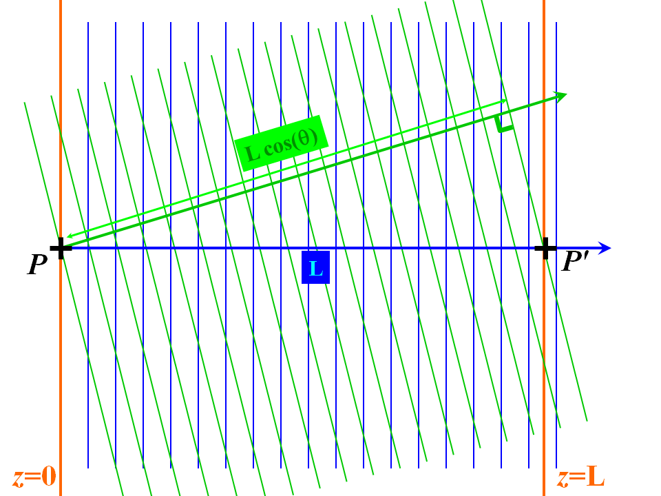
So let's set our minds to diffraction: first a quick summary of what I mean by this word. Consider a field on a plane, say $z = 0$ and split it up using Fourier decomposition of the field variation over the plane $z=0$ into constituent plane waves, which are "modes" of Maxwell's equations insofar that their propagation description is simply that the fields become phase delayed by a simple scale factor $\exp(i\,\mathbf{k}\cdot\mathbf{\Delta r})$ under the action of a translation $\mathbf{\Delta r}$. Each constituent plane wave has a different direction defined by the wavevector $\left(k_x, k_y, k_z\right)$ with $k^2 = k_x^2 + k_y^2 + k_z^2$ (i.e. the Fourier space equivalent of Helmholtz's equation), that is, all the wavevectors have the same magnitude but different directions. So, when we ask what the field looks like at a different value of $z$, we build the field up from our plane wave constituents at this point (use an inverse Fourier transform). However, now, because the wavevectors are all in different directions, the plane waves have all undergone different phase delays in reaching the new value of $z$ (even though their phase advances by $k$ radians per unit length in the direction of the respective wave vector). Therefore, the field's configuration gets scrambled by all these different phase delays. I sketch this idea in a drawing below:
You can see the "scrambling", $k_x$-dependent phase factor $\exp(i\, \sqrt{k^2 - k_x^2}\, z) = \exp\left(i\, k\, \cos\theta_x\,\right)$ (where $\theta_x$ is the angle that the plane wave with wavevector $(k_x, k_z)$ makes with the $z$-axis) will yield the complicated scrambling you see as "diffraction". Various approximations, notably Fraunhofer and Fresnel, are applied to this integral. The angle a Fourier component with $x$ component of wavenumber $k_x$ makes with the $z$-axis is $\theta = \arcsin (k_z/k)\approx k_s/k$. So we see that the Fourier transform of the transverse field dependence defines the divergence. In the above, we see a reciprocal relationship between a rough measure $2\pi/w$ of the maximum skew angle of the constituent plane waves and the "confinement" $w$ of the light field to the slit. The beam divergence and the beamwidth are indeed related by a Heisenberg-like inequality, and if we measure beam divergence and confinement by RMS values, we can indeed show the following from the basic properties of Fourier transforms. If $f(x)\in \mathbf{L}^2(\mathbb{R})$ and $F(k_x)$ is its Fourier transform, then the product of the root mean square spreads of both functions is bounded as follows. Without loss of generality, assume that $f(x)$ is real and $\int_{-\infty}^\infty x\,f(x)\,\mathrm{d}\,x = \int_{-\infty}^\infty k_x\,F(k_x)\,\mathrm{d}\,k_x= 0$, then:
Laser beam divergenceangle formula
The origin confocal resonator is considered the most efficient in most situations, as having the least losses, and the smallest mirror diameters. The beam waist is in the center of the cavity, and the end mirrors are identical geometrically, but they normally would have different reflectance coatings, to let some energy out.
I'm posting this as a second answer, since comments are limited in length. For a laser cavity (cylindrical geometry) of mirror separation $d$, the end mirrors are generally spherical having radii $R_1$ and $R_2$. We have to be sign conscious here. Concave mirrors have positive radii (for these purposes) while convex mirrors have negative radii. This is NOT the normal protocol in ordinary ray optics.
Due to Heisenberg uncertainty principle $\Delta x\Delta p\gtrsim \frac{\hbar}2$, one can't really make a quantum have zero momentum in any direction. So you can't say that photons go in the same direction - this is just a simplified description of laser operation. In reality, the thinner the beam, the higher the divergence.
When we plug $z = 0$ in, the integral is simply the inverse FT of (1) and we get our original slit field. But now put some nonzero value of $z$ in: because $k_x^2 + k_z^2 = k^2$, we have $k_z = \sqrt{k^2 - k_x^2}$ (assuming the field is running in the $+z$ direction), we get

Because only a tiny fraction of spontaneously-emitted photons are going to be headed in a useful direction, most of the energy imparted to them is going to be wasted; that's an unavoidable fact of life. On the other hand, much of the power that is fed to a laser doesn't get spent on spontaneous photon emission, but rather on photons that are stimulated by other photons. Thus, what's important is that spontaneous photons which aren't on useful paths should leave the lasing cavity as quickly as possible--never to return--and take as few extra photons along with them as possible (since every photon stimulated by a useless-path photon represents a waste of energy).
A stability diagram of $g_2$ plotted against $g_1$ ($y$ & $x$) shows that all stable resonators are in either the first or third quadrants; with the confocal resonator, $R_1 = R_2 = d$ at the origin ($g_1 = g_2 = 0$).
$$\int\limits_{-\infty}^\infty \frac{\sin\left(\frac{w\, k_x}{2}\right)}{k_x} \exp\left(i\, (k_x\, x + k_z\, z)\right) \mathrm{d} k_x\quad\quad\quad(2)$$
In general, the thicker your starting laser beam, the more collimated it is, so if you manage to make a (visible wavelength) laser with beam starting at 1cm thickness, you'll have almost perfectly collimated laser beam.
Whether you speak of photons or classical fields, the explanation is precisely the same. Maxwell's equations are the exact, single quantized description of photon propagation; I bang on about this topic ad nauseam here (How can we interpret polarization and frequency when we are dealing with one single photon?) and here (Electromagnetic radiation and quanta), so if you want more info, please see these answers;
As well as diffraction, there are also very definite engineering reasons why small divergence is deliberately introduced into beams, so that the cavity is easier to realize with stable modes, as noted in George E. Smith's answer. As a result, some lasers have divergences rather above my figures above (they are far from saturating the Heisenber-like inequality), but, by the same token, there are many lasers around that come very near to saturating this inequality. Needless to say, these latter are not the "entry level" ones used in laser pointers.
Plugging in a $w = 1\mathrm{mm}$ beamwidth for $\lambda =500\mathrm{nm}$ wavelength light, we get a beam divergence of $\Delta \theta \approx 10^{-5} \mathrm{radian}$. This is the typical beam divergence for a high quality 1mm laser chip. There is some arbitrariness in what measures we use for beam divergence (since Gaussian beams have theoretically infinite breadth): often it is the vertex angle of the cone containing $1 - e^{-2}$ of the beam's power. But I have equally seen the Gaussian RMS $\sigma$ or twice this value (one can speak of cone vertex angles or halfangles) used as the beamwidth; these are the $1 - e^{-2}$ beamwidth divided by $2\sqrt{2}$ and $\sqrt{2}$, respectively. You have to be a little bit careful how the beam divergence is defined.
By suitably curving the mirrors, it's possible to ensure that the nearly all of the initial photons that survive multiple trips through the lasing cavity will be on paths that can survive many more paths, while initial photons whose paths aren't going to survive many trips get weeded out quickly. This yields a major qualitative improvement in efficiency (large enough to turn a laser from something unworkable into something practical). There are engineering trade-offs between mirror size, efficiency, and beam coherence; having a laser's design more aggressively try to harness slightly-off-axis photons will make it more efficient, but make its beam less coherent.
If you try doing the same with a red laser pointer, you'll see that its light diverges quite a lot: after going several centimeters in direction of propagation, it'll already give image of several centimeters. The reason for this is that active zone of diode laser has diameter of order of several micrometers. This makes output beam quite thin, making $\Delta x$ small and thus $\Delta p$ high, and this is what leads to high divergence. Divergence angle would be $\sim \lambda/d=640\text{nm}/1\operatorname{\mu m}\sim 40^\circ$. Actual angle would depend on which transverse direction you select, because active zone is $\sim 10\times$ longer in one direction than in another.
Lasers work by having some of the "spontaneous" photons start out, by chance, heading in useful directions, picking up many additional photons to go with them, and then having many of those photons leave through the half-silvered mirror in a useful direction. Any energy imparted to photons which end up leaving through the mirror in a useful direction is energy well-spent. Any energy imparted to photons that end up leaving some other way is energy wasted.
Laser beam divergenceangle calculator
Stack Exchange network consists of 183 Q&A communities including Stack Overflow, the largest, most trusted online community for developers to learn, share their knowledge, and build their careers.
Select an option… Australian Capital TerritoryNew South WalesNorthern TerritoryQueenslandSouth AustraliaTasmaniaVictoriaWestern Australia
Sometimes the active laser medium, will have Brewster angle end mirrors, which render the laser plane polarized, and then the actual laser resonator mirrors are external, so operate in "air".
$$\Delta k_x \Delta x = \geq \frac{1}{2} \;\;\Rightarrow \;\;\frac{2\pi}{\lambda}\, \Delta\theta \,w \approx \frac{1}{2}\quad\quad\quad\quad(5)$$
Now to study diffraction in some detail. Think of a one-dimensional problem, so we have a uniformly lit slit of some finite width $w$ modeling the laser output; in this simplified system that there are only 2D wave vectors. The screen with the slit is in the $z = 0$ plane and the one orthogonal direction is the $x$ axis. All the Cartesian components of the fields fulfil the same (Helmholtz) equation, so we can discuss the principles by just looking at one scalar field $\psi$ (say, the electric field's $x$-component). Each plane wave has the form $\psi(k_x) = \exp\left(i \,(k_x\, x + k_z\, z)\right)$ The Fourier transform of the field output from the slit is then (I'll leave out factors of $2\pi$ in the unitary FT because scale factors don't affect the following):
All second and fourth quadrant resonators are unstable, and $g_1 \times g_2 = 1$ plots as first and third quadrant rectangular hyperbolas, beyond which other unstable resonators can be found.
Lowdivergence laser
the parallel mirrors cannot be perfectly parallel. they only need to be aligned enough so that photons can bounce between them long enough for lasing to occur. in practice this is not easy, but using intuitive geometry, a shorter and wider (radius) optical cavity allows more tolerance for misaligned mirrors (photons can reflect off axis for multiple passes without missing either mirror) with the draw back of producing a larger beam waist laser.
Let's finish with the Heisenberg uncertainty principle. The second part of my answer Time duration for pulse of single electron viewed as a wave shows how we can derive the following from the canonical commutation relationship $X\,P - P\,X = i\,\hbar\,I$ between conjugate quantum observables alone:
the use of concave mirrors aids the situation greatly. but as long as there is a nonzero beam radius, there will be divergence. for flat mirrors the perception of perfect collimation in the cavity is an illusion owing to the fact that the cavity is simply too short to observe any divergence.
in contrast a narrow and long cavity requires stricter alignment as a small deviation angle in photon travel within the cavity will quickly cause it to escape the medium after a few passes.
An extensive expose, appeared in "Applied Optics", 5, 1550, October 1966, and simultaneously in Proc IEEE, 54, 1312 , October 1966, and has been widely cited since.
We can always find co-ordinates for our quantum state Hilbert space such that $X$ is a simple multiplication operator and $P$ is the simple derivative operator $-i\hbar \mathrm{d}_x$
I was wondering why a laser beam diverges. If all the photons are in the same direction, I would imagine that it would stay that way over a long distance. I am aware that a perfectly collimated beam with no divergence cannot be created due to diffraction, but I am looking for an explanation based on photons rather than wave physics.
Laser beam divergencemeasurement
and as such position and momentum co-ordinates are mapped into one-another by the Fourier transform (because the eigenfunctions of $\mathrm{d}_x$ are of the form $e^{i\,k_x\,x}$). Therefore, exactly the same techniques and ideas apply as above, which is why the Heisenberg uncertainty principle seems so like the ideas in my answer. But it is most assuredly not the same thing. The HUP can't be applied to light for position-momentum because there are problems defining a position observable for the photon. This has to do with the fact that if $(\vec{E}, \vec{B})$ is a solution of Maxwell's equations, then things like $(x_j \vec{E}, x_j \vec{B})$ (where $x_j$ are the Cartesian co-ordinates) generally aren't (the Gauss laws showing divergencelessness in freespace are violated). Of course the HUP always applies to noncommuting (conjugate) observables and there are many pairs of those in QED. Contrast this with the scalar quantum electron state in the scalar massive particle nonrelativistic Schrödinger equation where the scalar eigenstates as $\mathbf{L}^2$ complete, so that if $\psi(x)$ is a quantum state in position co-ordinates, then $x \psi(x)$ is also in the Hilbert space of states. One can of course define an intensity field which yields a probability distribution to (destructively) photodetect a photon, but this is different from asking where (position observable) an electron electron is in an orbital. Electrons can be detected nondestructively - it is very hard to do this for photons. Also, position observables are readily defined only for scalar quantum states in nonrelativistic first quantized descriptions: there is of course no nonrelativitistic first quantised description of the photon. The bispinor valued electron state is also weird and the question of where the electron is cannot be addressed by a simple position observable either. Now you can still define the momentum with the usual observable, because the eigenfunctions of $-i\,\hbar\,\partial_j$ are plane waves, i.e. well defined momentum states. But when you talk of localization of photons - probability distributions of where to detect them - you are talking about diffraction. This has exactly the same mathematics as the HUP, as I have shown in my answer above. Having said this, Margaret Hawton is one of a few researchers who have taken a step back and looked at ways wherein we can meaningfully talk about photon positions, i.e. what we can salvage from the wreckage of the above problems: she derives a "position" observable with commuting components essentially by concocting something which has canonical commutation relationships with the momentum observable by definition and goes on to build a second quantized theory with these ideas. One finds that one gets what would wontedly be defined as a position observable PLUS some interesting and weird terms related to the photon's topological (Berry) phase. In other words, she explicitly shows how the wonted "no-go" theorems that forbid a photon position observable manifest themselves as extremely interesting terms that have to be added to the "wonted" and defective position observable. See her personal website for her papers.
$$\int\limits_{-\infty}^\infty \frac{\sin\left(\frac{w\, k_x}{2}\right)}{k_x} \exp\left(i\, (k_x\, x + \sqrt{k^2 - k_x^2}\, z)\right)\, \mathrm{d} k_x\quad\quad\quad(3)$$
Laser beam divergenceand spot size
Application Instructions for Flock Sheets: Apply Flock adhesive to fabric and allow it to dry at room temperature for 45-60 minutes. Place the transfer sheet with the flocking side up, and lay the fabric with the adhesive face down on top. Add another fabric layer between the heat source and the adhesive fabric. Heat set at 100°C-110°C for 2 minutes using a heat press or dry iron.
Some cautions. In lasers, the cavity is always filled (not necessarily completely) with some "Gain medium", solid, liquid or gas, so one must consider the actual refractive index of the gain medium, in doing Maxwell wave equation calculations, and use the right in cavity wavelength, which will surely change, when the beam exits the laser.
If one were to have two equally-sized perfectly-parallel mirrors, and assumes that the starting slopes of the photons are uniformly randomly distributed, and consider the life of a randomly-emitted photon starting at one end of the cavity; half of the ones that that hit the far-end mirror will miss the near-end mirror afterward; a third of those which hit the near-end mirror will miss the far-end mirror after that. Although the fraction of initial photons which have survived N bounces but die on the next will decrease as N increases, the amount of energy loss represented by each such initial photon will increase even more.
where $w$ is the slit width, and unless the slit is very wide, the Fourier transform has a wide spread of frequencies. This means that for $z = 0^+$ ("immediately downstream" of the the slit's output) the field is the superposition
Electromagnetic waves are diffracted, so a plane wave can only exist at a single location along the axis of propagation (in a uniform homogeneous medium) . In a semiconductor laser, the end mirrors might be planar crystal faces; but they aren't always; for example they aren't in VCSELs; where Bragg mirrors are often used.
An aspect I learned, which is different from the other answers given here, centers around the fact that an energized lasing medium will react to photons which go through it by producing more photons along the same path, but will also spontaneously release photons traveling on random paths. Any energy the lasing medium spends doing either of those things must be replaced from an outside power source in order to keep it energized.
Talking about photons doesn't mean giving up the concept of a spatial mode. If you look at a laser beam, which is diverging, and attenuate it to the level of single photons it still has the same spatial properties. Attenuation doesn't change the way light (or photons) are propagating. The assumption that all photons propagate in the same direction is wrong.
Laser beam divergenceformula
A cavity resonator with parallel end mirrors is unstable, so is a poor choice for a laser. In practice, there is a physical "gain medium" that the waves are propagating in in the resonator, and inhomogeneities in that medium will render the effective cavity not parallel; particularly in semiconductor lasers, where impurity doping, will render the refractive index non uniform.
$$\sqrt{\frac{\int_{-\infty}^\infty x^2\,|f(x)|^2\,\mathrm{d}\,x}{\int_{-\infty}^\infty |f(x)|^2\,\mathrm{d}\,x}}\;\sqrt{\frac{\int_{-\infty}^\infty k_x^2\,|F(k_x)|^2\,\mathrm{d}\,k_x}{\int_{-\infty}^\infty |F(k_x)|^2\,\mathrm{d}\,k_x}} \leq \frac{1}{2}\quad\quad\quad\quad(4)$$
and moreover the inequality is saturated by Gaussian $f(x)$ $f(x) \propto \exp\left(-\frac{x^2}{2\,\sigma^2}\right)\,e^{-i\,k_0\,x}$ for some real constants $\sigma$ and $k_0>0$, i.e. such functions (their Fourier transforms are also Gaussian) achieve equality in the above bound.
In a DPSS laser the active material will have diameter of order of hundreds of micrometer, and the exiting beam will start from even smaller diameter for various reasons. The divergence is quite small: if you remove the collimating lens, your light image from a green laser pointer will be several centimeters after the light goes several meters. Divergence angle would be $\sim \lambda/d=532\text{nm}/100\operatorname{\mu m}\sim0.3^\circ$.


 Ms.Cici
 8618319014500