
CCD Camera Gain Measurement - camera gain
5. A locust is located 25mm from a convex lens with focal length of 35mm. Where is the image located? What kind of image is it? Is it rightside-up or upside-down? If the locust is 3.0 cm tall, how tall is the image? Solve this problem by (a) drawing a ray-tracing diagram, and (b) calculations. Solution video
2. You have a lens with f=35mm, and an object 60mm away from it. Draw a ray-tracing diagram to find the location of the image. Measure the resulting di.
4. A locust is located 25mm from a convex lens with focal length of 15mm. Where is the image located? What kind of image is it? Is it rightside-up or upside-down? If the locust is 3.0 cm tall, how tall is the image? Solve this problem by (a) drawing a ray-tracing diagram, and (b) calculations. Solution video
Beamsplitter Hamiltonian
This Beam Splitter coating is designed to transmit 50% and reflect 50% ±10% from 425-650nm at 45 degrees angle of incidence.
Don't forget that you have calculated 1/di, not di itself. Now, take the inverse to find the final answer.
Hong-Ou-Mandel
10. SPREADSHEET: Create a spreadsheet with two input cells (lens focal length and object distance) and two outputs (image distance and magnification).
Jul 11, 2023 — Arm and Base · Ocular lens – magnifies by 10X · Revolving nosepiece – contains 3 objective lenses · Stage and stage clips – hold the slide for ...
2019227 — By eliminating reflections, AR coating also makes your eyeglass lenses look nearly invisible so people can see your eyes and facial expressions ...
beamsplitter中文
EXAMPLE: here is a completed diagram for a lens with f = 22 mm and an object that is 33 mm away. Notice that the image is upside-down and larger than the object. (NOTE: this diagram was originally drawn at 1:1 scale. Your browser probably won't display it at the same scale.)
Fiber Optic Fabric. As fiber optics have become more popular in wearables, fiber optic fabric is now available. Here the strands are stitched together into a ...
$83.99 Objective Selector | Nikon Instruments Inc. Nikon Plan Apo 20x infinity microscope; Nikon Plan APO 20X/0.75 ...
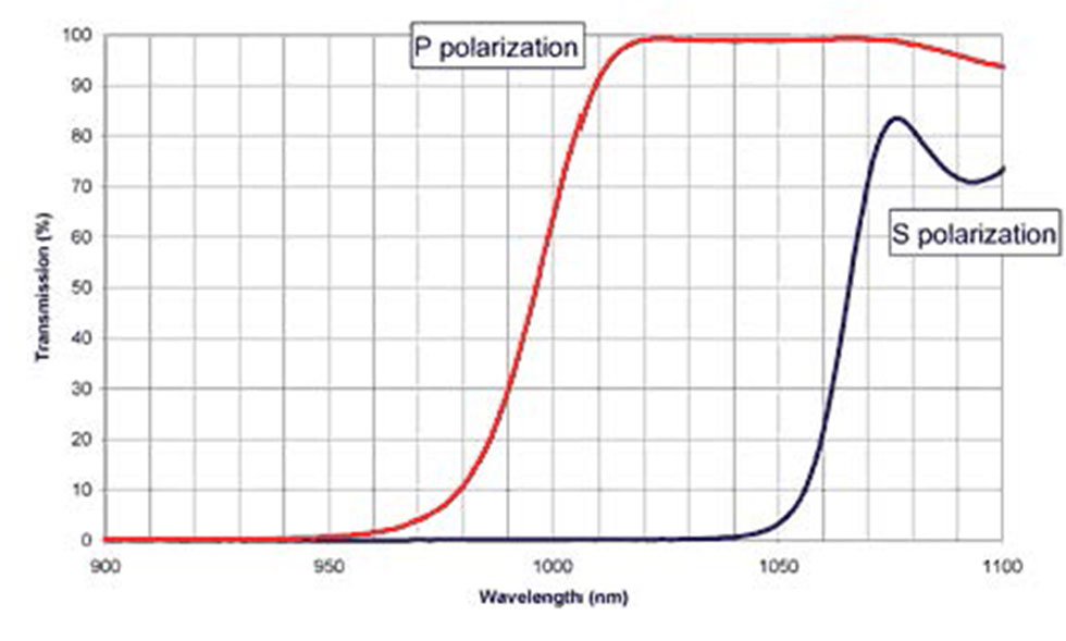
This Beam Splitter coating provides greater than 97% transmission of “P” polarized light and greater than 97% reflectance of “S” polarized light at single specified wavelength. Generally the angle of incidence is specified between 45 and 65 degrees.
Here's a different version that doesn't look as fancy, but handles diverging lenses as well as converging, and also converging and diverging mirrors.
Dielectric coatings as described here have the advantage of being non-absorbing and so allow for greater throughput of energy. These dichroic filters for example, have a dielectric coating that can be used for a 50/50 beam splitter. In contrast, Inconel is limited to 30% transmission and 30% reflection due to the absorption inherent in the metal film. Standard dielectric beam splitter coatings include 30/70, 50/50, and 70/30. We welcome inquiries regarding any custom requirements you may have.
• Draw your lens as a vertical line. Although lenses do have some thickness and curvature to them, don't worry about that — just draw a line. (The thickness is usually small compared to the distances involved and can be ignored.) • Draw the principal axis — a long line perpendicular to the lens through its midpoint. • On the principal axis, draw two tick-marks a distance f from the lens on both sides. At this point your drawing should look something like this:
Polarizingbeamsplitter
Jul 28, 2023 — The calculator will evaluate and display the Image Distance. All Distance Calculators · Ball Lens Focal Length Calculator · Focal Width/Length ...
NOTE: In order for all this to work, the drawing must be drawn carefully, to scale. If the scale is other than 1:1 (i.e. full size) then be sure to right down what scale you are using.
Wollaston prism
6. A car is located 60.00 m from a converging lens with focal length 60.00 cm. Calculate where the image is, and the magnification. Solution video
Partially transmitting metals also make very useful beam splitter coatings. Two common metals used for this purpose are Inconel and chrome. Metal beam splitters are often very broad and can cover a much wider spectrum of wavelengths than their dielectric counterparts.
Dailytop UV Light Sanitizer,UVC Light Sanitizer for Room,Ultraviolet Light with 3- Speed Timing and Remote Control,38W 110V UV Lamp for Home ...
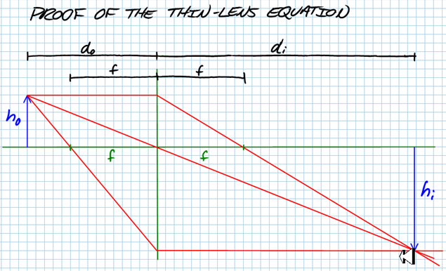
The linear magnification describes the ratio of the size of the image to the size of the actual object. The ratio is the same as the ratio of the distances.
Quantum mechanical losslessbeamsplitter su 2 symmetry and photon statistics
where hi and ho are the heights of the image and object, respectively. A negative sign on the magnification or image height implies that the image is inverted (upside-down).
Partially transmitting metals also make very useful beam splitter coatings. Two common metals used for this purpose are Inconel and chrome. Metal beam splitters are often very broad and can cover a much wider spectrum of wavelengths than their dielectric counterparts. Dielectric coatings as described here have the advantage of being non-absorbing and so allow for greater throughput of energy. These dichroic filters for example, have a dielectric coating that can be used for a 50/50 beam splitter. In contrast, Inconel is limited to 30% transmission and 30% reflection due to the absorption inherent in the metal film. Standard dielectric beam splitter coatings include 30/70, 50/50, and 70/30. We welcome inquiries regarding any custom requirements you may have.
Typically higher index glass to maximize polarization separation. This Beam Splitter coating is designed for a substrate refraction index of approximately 1.80.
Compact Slim Photodiode Power Sensor · For Optical Power Measurements in Tiny Spaces Such as 16 mm Cage Systems · Wavelength Range: 400 - 1100 nm · Very Slim ...
9. A stamp, 2.0 cm tall, is being held 7.0 cm from a lens that has focal length -5.5 cm (i.e. it's a diverging lens). Where is the image located? What kind of image is it? Is it rightside-up or upside-down? How tall is the image? Solve this problem by (a) drawing a ray-tracing diagram, and (b) calculations. Solution video
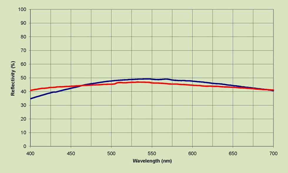
This Beam Splitter coating has an average transmission of 45% and 45% reflectance from 475-625nm for both “S” and “P” polarizations.
Aspheric lenses from Edmund Optics are available coated or uncoated · LFW Staff. TECHSPEC precision aspheric lenses focus light while they eliminate spherical ...
Thorlabsbeamsplitter
8. A stamp, 2.0 cm tall, is being held 7.0 cm from a lens that has focal length +5.5 cm. Where is the image located? What kind of image is it? Is it rightside-up or upside-down? How tall is the image? Solve this problem by (a) drawing a ray-tracing diagram, and (b) calculations. Solution video
Partially transmitting metals make very useful beam splitter coatings. Two common metals used for this purpose are Inconel and chrome. Metal beam splitters are often very broad and can cover a much wider spec- trum of wavelengths than their dielectric counterparts. In this ex- ample, a single layer of Inconel with approximately equal reflectance and transmittance is shown.
Mach-Zehnder interferometer
• Draw the object (usually depicted as an arrow) to the left of the lens, at the distance specified in the problem. • Light rays are being diffusely reflected by all points on the object, in all directions, but we only need to look at what happens to three rays (the so-called principal rays) coming from the top of the object. First the one ray that happens to be going parallel to the principal axis will, after hitting the lens, go through the right-hand focal point. We call this first ray the parallel-focus ray. The second is the focus-parallel ray: it's the ray that starts out in the direction of the left-hand focal point. After going through the left focal point it hits the lens and will end up going parallel to the principal axis. The third is the central ray: any ray that goes through the center of a lens comes out with its direction unchanged. • Where the three rays intersect is the tip of the image.
7. A stamp, 2.0 cm tall, is being held 3.0 cm from a lens that has focal length +5.5 cm. Where is the image located? What kind of image is it? Is it rightside-up or upside-down? How tall is the image? Solve this problem by (a) drawing a ray-tracing diagram, and (b) calculations. Solution video
Designed for the broadest range of demanding fans, the ROG Crosshair X670E Extreme features 20 + 2 power stages, DDR5 support, five M.2 slots, ROG Gen-Z.2, ...
Thin-lens Equation If the distance of the object from the lens is called do, the distance of the in-focus image from the lens is called di, and the focal length of the lens is f, then
When a microscope objective shows a non-symmetric optical behavior, as in the case of spherical aberration (as well as astigmatism and/or coma), the wavefront ...
Where is the Image? The image produced by a converging lens will only be at the focal point if the object is infinitely far away. This makes the rays from each point of the object parallel with each other, just like in the "Refraction" and "Reflection" notes pages. If the object comes close to the lens, the rays entering the lens are diverging when they hit the lens, the lens will have a 'harder' time converging them, and the image will be further away from the lens than the focal length. In fact, if you bring an object too close to a lens, the rays hitting it will be diverging at such a great angle that the lens, even though it's a 'converging' lens, will fail to converge the light to a real image. Let's see how you can find out exactly where the image will be for all object distances. There are two ways: using a scale drawing (called ray tracing) and calculating (using the so-called thin-lens equation).
1. Go to http://phet.colorado.edu/simulations/lens/lens.swf and play with the lens simulation. Turn on the principal rays. Move the object closer and further from the lens and verify for yourself that:
11. A locust is located 25mm from a concave (diverging) lens with focal length of -35mm. Where is the image located? What kind of image is it? Is it rightside-up or upside-down? If the locust is 3.0 cm tall, how tall is the image? Solve this problem by (a) drawing a ray-tracing diagram, and (b) calculations.
Notice what the thin-lens equation says if the object is very far away. If do is very large, then 1/do is very close to zero, and we have di ≈ f. In other words, the image is located at the focal length from the lens only when the wavefront entering the lens are coming from a distant object and therefore close to plane waves. Recall that this was how we first defined the focal length.
Beam Splitter (BS) is a term used to describe various coatings which divide a beam of light into separate beams. Dichroic filters are often called beam splitters. In this section, we will be describing beam splitters that divide light at each wavelength of interest into two separate beams. These beam splitters are typically designed for an incident angle around 45 degrees from normal.


 Ms.Cici
 8618319014500