
Calcium Fluoride Window - calcium fluoride window
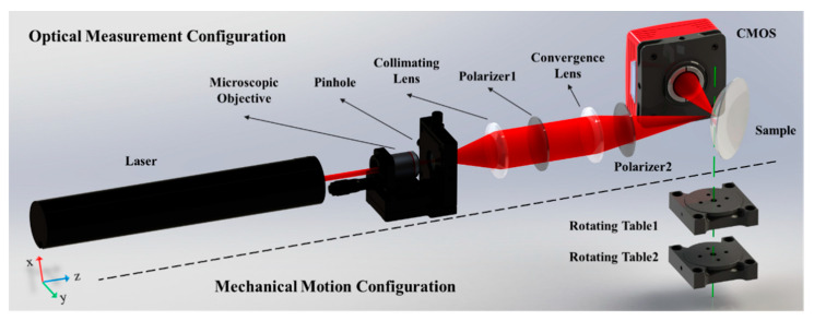
Figure 2A shows the layout of the optical measurement configuration of the system. The thin laser beam passes through the microscopic objective and collimating lens to generate a broad collimated laser beam, which is used as a light source. The broad beam is focused by a convergence lens to the focal point as a focusing probe, which is coincident to the surface vertex of the sample. The incident angle of the chief ray of the probe is close to the Brewster angle. Polarizers 1 and 2, through which the light passes, are both in P polarization state, guaranteeing that the probe is a P-polarized beam. After the probe is reflected by the sample, the reflected light propagates to the CMOS detector placed at a distance d away from the sample. The resolution and the pixel size of the image plane are denoted as M × N and p, respectively.
(A) Flow chart for calculating the refractive index; (B) Minimum intensity position θEi in each row; (C) The maximum θEmax corresponding to the angular offset from the center θE.
This symmetric scheme can reduce the influence of several systematic errors. The verification is presented in Section 4.
For the measurement of the lens sample, the calculation for θEmax shall be no greater than two pixels. Thus, the measurement error σθE can be estimated as σθE ≈ 0.0025° according to Equation (4). σnE can be obtained with Equation (18) as
where is σn0 affected by the environment parameters, such as pressure, temperature, and humidity. Considering the parameters above, σnair can be obtained by [31]
by TW Cronin · 2011 · Cited by 147 — By contrast, polarization of light in water, while visible in most directions of view, is generally much weaker. In air, the surfaces of natural objects often ...
Aug 21, 2024 — Contrasting with traditional spherical lenses, aspherical lenses have a more complex surface profile – so, they protect your images from many ...
Refractive indexof water
Contrast sensitivity is a measure of the ability to discern different luminances in a static image. It varies with age, increasing to a maximum around 20 years at spatial frequencies of about 2–5 cpd; aging then progressively attenuates contrast sensitivity beyond this peak. Factors such as cataracts and diabetic retinopathy also reduce contrast sensitivity.[11] In the sweep grating figure below, at an ordinary viewing distance, the bars in the middle appear to be the longest due to their optimal spatial frequency. However, at a far viewing distance, the longest visible bars shift to what were originally the wide bars, now matching the spatial frequency of the middle bars at reading distance.
Figure 8 shows the structure of the tested prism and spherical lens samples. Detailed information about the material, the reference value of the refractive index, and the structural parameters is listed in Table 1. The surface with ROC of R1 was used for reflection in the experiment for the lens. The Rayleigh length of the focusing probe beam was around 160 μm, and the maximum sag variation in the target surface within the laser reflection area was around 7.5 μm, which was less than the Rayleigh length, proving that the reflection area could be treated as a point. The reference refractive index of the samples was settled from the glass database. The material H-K9L and N-BK7 were glasses with the same properties but produced by different companies, so their refractive indices were the same.
For the focusing probe beam in Figure 1, the focal point of the convergence lens corresponds to the coordinate origin of the model and the optical axis of the incident light corresponds to the Z axis. The chief ray of the incident light lies on the yoz plane, and thus the angle γ is zero and θ is equal to the incident angle α, which is close to the Brewster angle. Given that the incident angles of the rays at other positions of the beam distribute around the chief ray similarly to a cone, the values of θ and γ distribute around the Brewster angle and zero, respectively. The distribution range is determined by the focal length and diameter of the beam. Given that the reflected light is collected by the CMOS, θ and γ correspond to the row and column coordinates, respectively. After the θ and γ of each CMOS pixel are determined, the incident angle α can be calculated with Equation (3). According to Snell’s Law, the result that the reflected intensity distribution versus the incident angle consists of a dark slit with a minimum close to zero can be obtained.
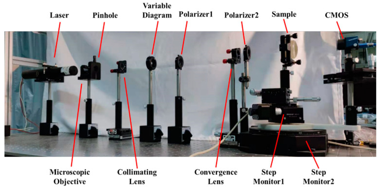
This section demonstrates the abovementioned principle with the refractive index measurement system, as shown in Figure 7. A He-Ne laser with a wavelength of 632.8 nm was used as the light source. Expanded by the microscopic objective, the pinhole, and the collimating lens, the diameter of the collimated laser beam was approximately 10 mm. The extinction ratio of the polarizers was 500:1. The focal length and the diameter of the convergence lens were 175 mm and 25.4 mm, respectively. The CMOS (Daheng Imaging, MER-302-56U3C) was placed at d = 150 mm from the focal point of the convergence lens, with M × N = 2048 × 1536 resolution and pixel size p = 3.45 μm. The sample and the CMOS rotations were realized by a pair of co-axis stepping motor rotating tables (BOCIC, MRS-101 and MRS-103). The stepping angle of each of the tables was around 1.3 × 10⁻³ degrees.
The results of the measurement of the samples made with H-K9L(N-BK7), including samples 1, 2, 3, and 4, are listed in Table 2.
Campbell and Robson (1968) showed that the human contrast sensitivity function shows a typical band-pass filter shape peaking at around 4 cycles per degree (cpd or cyc/deg), with sensitivity dropping off either side of the peak.[3] This can be observed by changing one's viewing distance from a "sweep grating" (shown below) showing many bars of a sinusoidal grating that go from high to low contrast along the bars, and go from narrow (high spatial frequency) to wide (low spatial frequency) bars across the width of the grating.
The Olympus FluoView FV1000MPE is a multi-photon laser scanning microscope that allows fluorescence imaging deep within specimens.
Root mean square (RMS) contrast does not depend on the spatial frequency content or the spatial distribution of contrast in the image. RMS contrast is defined as the standard deviation of the pixel intensities:[6]
For example, in the case of graphical computer displays, contrast depends on the properties of the picture source or file and the properties of the computer display, including its variable settings. For some screens the angle between the screen surface and the observer's line of sight is also important.
This research was funded by the National Natural Science Foundation of China (NSFC) (51735002) and the Strategic Priority Research Program of the Chinese Academy of Sciences (XDA25020317).
One experimental phenomenon is the inhibition of blue in the periphery if blue light is displayed against white, leading to a yellow surrounding. The yellow is derived from the inhibition of blue on the surroundings by the center. Since white minus blue is red and green, this mixes to become yellow.[5]
Overall, the average of the data collected clockwise is greater than the reference at 10−3 order, while for the anticlockwise data, the average is less than the reference at a similar order. With and without using the symmetry measurement, the accuracy can reach 10−3 and 10−4, respectively. The second group of experiments indicated that for the samples with different materials, the results are relatively stable.
Yes, focal length is expressed in millimetres (mm). · In case of a focal length like 16–80mm, the higher number usually means a bigger zoom, ...
where the pressure is nearly a normal atmosphere, σPa ≈ 0; σK = 6.4 °C, and σH = 11.6%. The value of tan(θE + θS) is equal to the reference refractive index.
A separate study by Knoll et al[25] investigated thresholds for point sources by requiring subjects to vary the brightness of the source to find the level at which it was just visible. A mathematical formula for the resulting threshold curve was proposed by Hecht,[26] with separate branches for scotopic and photopic vision. Hecht's formula was used by Weaver[27] to model the naked-eye visibility of stars. The same formula was used later by Schaefer[28] to model stellar visibility through a telescope.
which also matches the experimental accuracy of approximately 5 × 10⁻⁴. Finally, the accuracy of the refractive index measurement method with the symmetric measurement scheme can reach 10−4.
incline ; lower or bend (the head or upper body), as in a nod or bow. She inclined her head to the student · bring down, get down, let down, lower, take down.
Then, the error estimation with the symmetric measurement scheme as proposed in Section 4.2 is given. σnair and σnE are the same as in Equations (22) and (24). However, for σnS, the influence of σβ, σy1, and σy2 can be reduced. σnS can be obtained by
Conceptualization, Y.H.; methodology, J.L.; software, J.L.; validation, J.L. and Y.H.; formal analysis, J.L.; data curation, J.L.; writing—original draft preparation, J.L.; writing—review and editing, Y.H. and Q.H.; project administration, Y.H. and Q.H.; funding acquisition, Y.H. and Q.H. All authors have read and agreed to the published version of the manuscript.
Refractive indexof lens
Considering the effect of the above-mentioned errors on the measurement result, the synthetic measurement error of the refractive index σn is
The refractive index, defined as the ratio of the velocity of light in a vacuum and the material, is one of the most important physical parameters of optical glass. With its considerable influence on the working characteristics of optical systems, high-accuracy measurement of this parameter is required. Since the early 1900s, various methods have been proposed [1], including prism coupling [2], critical angle [3], interferometry [4,5], and ellipsometry [6]. Some of them can even determine the refractive index and the structure of the sample simultaneously [7,8,9,10]. These methods are now widely used and can reach high accuracy of up to 10−6, but they are only available for prisms and parallel plates. Samples with only spherical or aspheric surfaces, such as lenses, cannot be tested. However, the measurement of the refractive index of a lens is equally important because of its possible changes during the manufacturing procedure, which may considerably affect the optical properties [11,12].
Refractive index in glassexperiment
A refractive index measurement method using Brewster’s Law and a focusing probe beam is proposed in this study. A P-polarized laser beam is focused on the surface vertex of the sample as a probe with a size of approximately 10 microns and is then reflected to an array detector. According to Brewster’s Law, a dark slit corresponding to the Brewster angle exists in the intensity distribution of the reflected light. Image processing is used to calculate the Brewster angle and the refractive index. In addition, a symmetric measurement scheme is proposed to reduce the error introduced by alignment errors. A prism and four spherical lens samples with different refractive indices or radii of curvature were tested with the proposed method. The results indicated that the accuracy can reach 10−4.
Secure .gov websites use HTTPS A lock ( Lock Locked padlock icon ) or https:// means you've safely connected to the .gov website. Share sensitive information only on official, secure websites.
The refractive index is tested by noninterference measurement, given that the method is robust to noise and environmental vibrations.
All of the above-mentioned are undetermined systematic errors, and thus σθS needs to be synthesized by the root square sum method. The angular measurement errors σθβ, σθx1, σθx2, σθy1, σθy2 caused by σβ, σx1, σx2, σy1, σy2 can be respectively expressed as
(A) Intensity curve in three typical rows in the measurement of sample 1; (B) Minimum intensity position curve in the measurement of sample 1.
Refractive index in glassformula
The measurement error σnE of the refractive index caused by the angular measurement error σθE of incident angle θE can be obtained by differentiating Equation (5) with respect to σθE as
where intensities I i j {\displaystyle I_{ij}} are the i {\displaystyle i} -th j {\displaystyle j} -th element of the two-dimensional image of size M {\displaystyle M} by N {\displaystyle N} . I ¯ {\displaystyle {\bar {I}}} is the average intensity of all pixel values in the image. The image I {\displaystyle I} is assumed to have its pixel intensities normalized in the range [ 0 , 1 ] {\displaystyle [0,1]} .
Compared with the current non-immersion method, the proposed method does not require the structural parameters of the tested samples. Thus, the method can be used regardless of the shape of the sample, and the measurement process is clear and simple.
To assess a patient's contrast sensitivity, one of several diagnostic exams may be used. Most charts in an ophthalmologist's or optometrist's office will show images of varying contrast and spatial frequency. Parallel bars of varying width and contrast, known as sine-wave gratings, are sequentially viewed by the patient. The width of the bars and their distance apart represent spatial frequency, measured in cycles per degree.
This section collects any data citations, data availability statements, or supplementary materials included in this article.
Refractive indexof Perspex
Rotating the sample and the CMOS around the axis of the rotating tables can change the incident angle of the chief ray. The initial position of the sample and the CMOS is shown as a dotted line in Figure 2A. The rotation angle of the sample and the CMOS are marked as ω1 and ω2, respectively. Given that the incident angle is equal to the reflected angle, then ω2 = 180° − 2ω1. According to Snell’s Law, when the incident angle is close to the Brewster angle, the intensity distribution of the reflected light with a dark slit existing near the center can be illustrated as in Figure 2B. The center position of the distribution corresponds to the chief ray of the reflected light. Figure 2C shows the intensity curve versus the incident angle. The minimum position of the intensity curve corresponds to the Brewster angle.
In general, m f {\displaystyle m_{f}} refers to the contrast of the periodic signal f {\displaystyle f} relative to its average value. If m f = 0 {\displaystyle m_{f}=0} , then f {\displaystyle f} has no contrast. If two periodic functions f {\displaystyle f} and g {\displaystyle g} have the same average value, then f {\displaystyle f} has more contrast than g {\displaystyle g} if m f > m g {\displaystyle m_{f}>m_{g}} .[10]
According to the experimental system, Table 5 shows the estimated error limits of σβ, σx1, σx2, σy1, and σy2. For the measurement of sample 5, θS is set at 1.0647 rad, and the turning radius R = 150 mm, equal to the distance between the CMOS and the rotating center. By the estimated error in Table 5 and Equations (10)–(16), the measurement error σnS can be calculated as
with I {\displaystyle I} and I b {\displaystyle I_{\mathrm {b} }} representing the luminance of the features and the background, respectively. The measure is also referred to as Weber fraction, since it is the term that is constant in Weber's Law. Weber contrast is commonly used in cases where small features are present on a large uniform background, i.e., where the average luminance is approximately equal to the background luminance.
Visual acuity is a parameter that is frequently used to assess overall vision. However, diminished contrast sensitivity may cause decreased visual function in spite of normal visual acuity.[12] For example, some individuals with glaucoma may achieve 20/20 vision on acuity exams, yet struggle with activities of daily living, such as driving at night.
The error of the result obtained by Equation (6) consists of the angular measurement error σθS and σθE. σθE is a random measurement error caused by the algorithm and does not change with or without the symmetric measurement. However, the error sources of σθS, including σβ, σx1, σx2, σy1, σy2, are all systematic errors that consist of positive or negative values. The error clockwise and anticlockwise are denoted as θS1 and θS2, respectively. For the quantitative evaluation of the errors, the angle approximation and equivalent infinitesimal can be used to simplify the equals as
The reason for the dark silt formation is presented below. The intensity distribution of the reflected light is determined by the distribution of the incident light and the reflectivity, while that of the collimated laser beam is generally Gaussian and the reflectivity can be calculated by the incident angle. For the focusing probe beam, the incident angles vary at different positions, which follows the model in Figure 3.
Finally, without the symmetric measurement scheme, the refractive index measurement error σn is estimated with Equation (19) as
The synthesis error matches the experiment results, which is approximately 5 × 10⁻³ for both clockwise and counterclockwise data.
The high-frequency cut-off represents the optical limitations of the visual system's ability to resolve detail and is typically about 60 cpd. The high-frequency cut-off is also related to the packing density of the retinal photoreceptor cells: a finer matrix can resolve finer gratings.
Using the results of a contrast sensitivity exam, a contrast sensitivity curve can be plotted, with spatial frequency on the horizontal, and contrast threshold on the vertical axis. Also known as contrast sensitivity function (CSF), the plot demonstrates the normal range of contrast sensitivity, and will indicate diminished contrast sensitivity in patients who fall below the normal curve. Some graphs contain "contrast sensitivity acuity equivalents", with lower acuity values falling in the area under the curve. In patients with normal visual acuity and concomitant reduced contrast sensitivity, the area under the curve serves as a graphical representation of the visual deficit. It can be because of this impairment in contrast sensitivity that patients have difficulty driving at night, climbing stairs and other activities of daily living in which contrast is reduced.[16]
Refractive indexof diamond
According to Equation (5), the measurement error σn of the refractive index of the sample is mainly caused by that of air σn0, the angular measurement error of the incident angle at the center position σθS, and the angular measurement error of the angular offsets σθE.
The measurement error σnS of the refractive index caused by the angular measurement error σθS of incident angle θS can be obtained by differentiating Equation (5) with respect to σθS as
For the measurement of samples 2, 3, and 4, the reference value of the refractive index was also 1.5151. The average refractive indices of the averaged result of clockwise and anticlockwise data were 1.5146, 1.5145, and 1.5146, respectively. Moreover, the standard deviations were 7.5 × 10⁻⁵, 6.4 × 10⁻⁵, and 7.8 × 10⁻⁵. The averages were approximately equal to that of sample 1, and the standard deviations were in the same order of magnitude. For the data collected clockwise and anticlockwise, similar conclusions could be drawn.
The refractive index is one of the most important parameters of optical glasses and has a significant effect on optical properties. The measurement of optical glasses, especially for optical elements such as lenses, is urgently needed. However, several presented methods require the immersion of the sample in liquid and provide indirect measurements, while others require structural parameters as priori knowledge, which is complex and time-consuming. In this study, a Brewster-Law-based direct and simple measurement method for the refractive index of glasses with arbitrary shapes is proposed, and a laser beam is focused on the surface of the sample as a probe. The incident angle of the chief ray is close to the Brewster angle. The reflected light is collected by an array detector. The refractive index is calculated from the minimum intensity position obtained with image processing. Additionally, a symmetric measurement scheme is proposed to improve the accuracy. Using these methods, a prism and four spherical lens samples with different refractive indices or radii of curvature are tested and error analyses are carried out. Results indicate that the accuracy can reach 10−4.
σθS is caused by various error sources, including the tilt angle σβ, misalignment errors σx1 and σy1 of the surface vertex and the rotating center of the CMOS, and the misalignment errors σx2 and σy2 of the focal point and rotating center of the CMOS, as shown in Figure 10.
Based on Equations (21) and (22), the expressions of the error coefficients of σβ, σx1, σx2, σy1, σy2 for σθS1, σθS2, and σθS in Equations (10)–(14) can be simplified as listed in Table 4. With the symmetric measurement scheme, the errors from σβ, σy1, and σy2 can be reduced, while those from σx1 and σx2 remain the same, verifying the method’s feasibility.
First, the error estimation without the symmetric measurement scheme was conducted as proposed in Section 4.1. The measurement error σnair caused by that of the refractive index of the air σnair is calculated with Equation (8) as
Second, the angular offset θE between the chief ray corresponding to the horizontal center of the image and the Brewster-angle ray corresponding to the intensity minimum position is obtained by the image processing algorithm shown in Figure 5A. The first two steps draw the intensity distribution versus the column coordinate (representing θ) of each row, as shown in Figure 5B, and find the minimum intensity column coordinate in each row, marked as θEi, where i = 1, 2, … M. Generally, influenced by the angle γ, θEi varies with the row coordinate i. The next step is finding the angular offset θE. According to Equation (3), only when γ is zero is the incident angle α equal to θ. In other situations, α is greater than θ. If γ is farther from zero, α reaches the Brewster angle with a smaller θ. Thus, only in the row where γ is zero can α be equal to θ and θEi reach a maximum. Figure 5C shows that the maximum value of θEi, denoted as θEmax, can be adopted to calculate the angular offset θE as

Refractive indexof air
For the measurements of sample 5, the reference value of the refractive index was 1.7999 at 632.8 nm. For the data collected clockwise, the average was 1.8055 and the standard deviation was 1.0 × 10⁻⁴. For the data collected anticlockwise, the average was 1.7953 and the standard deviation was 5.1 × 10⁻⁵. For the averaged result of clockwise and anticlockwise data, the average was 1.8004 and the standard deviation was 7.1 × 10⁻⁵. With and without the symmetry measurement, the accuracy can reach around 5 × 10⁻³ and 5 × 10⁻⁴, respectively.
Publisher’s Note: MDPI stays neutral with regard to jurisdictional claims in published maps and institutional affiliations.
In the measurement of the refractive index of lenses, the liquid immersion method plays an important role. Smith [13] immersed a lens in a mixed liquid with varying refractive indices until it approximated that of the lens. Measuring the refractive index of the liquid can thus indirectly obtain that of the lens with an accuracy of 4.6 × 10⁻⁴. However, the mixed liquid used must be miscible, which is time-consuming for preparation. In addition, most of the miscible organic compounds are poisonous in nature. Other liquid immersion methods use non-miscible liquids. R. S. Kasana, et al. proposed a nondestructive technique using a Murty shearing interferometer [14]. The tested spherical lens is immersed in standard liquid with a certain refractive index inside a glass cell, from which the interferometric fringe is generated. The refractive index can be measured by analyzing the fringes with an accuracy of 10−4. Similarly, the refractive index of a lens can be measured by using computed tomography [15], Fabry–Perot interferometer [16], optical grating [17], acousto-optic grating [18], and Ronchi grating [19]. In these methods, the refractive index of the liquid does not need adjustments to fit that of the sample. However, the lens immersed shall be aligned to the optical axis, which is difficult in the liquid environment. Given that the refractive indices of the samples are obtained indirectly by measuring that of the liquid, the accuracy is limited by that of the liquid index measurement [20,21].
Recent studies have demonstrated that intermediate-frequency sinusoidal patterns are optimally-detected by the retina due to the center-surround arrangement of neuronal receptive fields.[17] In an intermediate spatial frequency, the peak (brighter bars) of the pattern is detected by the center of the receptive field, while the troughs (darker bars) are detected by the inhibitory periphery of the receptive field. For this reason, low- and high-spatial frequencies elicit excitatory and inhibitory impulses by overlapping frequency peaks and troughs in the center and periphery of the neuronal receptive field.[18] Other environmental,[19] physiological, and anatomical factors influence the neuronal transmission of sinusoidal patterns, including adaptation.[20]
The refractive index measurement clockwise, the refractive index measurement anticlockwise, and the average refractive index are abbreviated as RIC, RIAC, and RIA, respectively, in the table.
For the measurements of sample 1, the reference value of the refractive index was 1.5151 at 632.8 nm. For the data collected clockwise, the average was 1.5187 and the standard deviation was 9.0 × 10⁻⁵. The average was approximately 3.6 × 10⁻³ greater than the reference, but the data had limited diversity. For the data collected anticlockwise, the average and the standard deviation were 1.5104 and 5.1 × 10⁻⁵, respectively. The average was 4.7 × 10⁻³ less than the reference. However, the diversity remained low. For the averaged result of clockwise and anticlockwise data, the average was 1.5146 and was only approximately 5.0 × 10⁻⁴ less than the reference. The standard deviation was 4.6 × 10⁻⁵.
The rationale behind this is that a small difference is negligible if the average luminance is high, while the same small difference matters if the average luminance is low (see Weber–Fechner law). Below, some common definitions are given.
In Section 2.3, we propose a symmetric measurement scheme to improve the system’s accuracy. The results show the effectiveness of the method. Here, the error analyses of the symmetric measurement are given to verify the method theoretically.
Contrast is the difference in luminance or color that makes an object (or its representation in an image or display) visible against a background of different luminance or color.[1] The human visual system is more sensitive to contrast than to absolute luminance; thus, we can perceive the world similarly despite significant changes in illumination throughout the day or across different locations.[2]
There are many possible definitions of contrast. Some include color; others do not. Russian scientist N. P. Travnikova [d] laments, "Such a multiplicity of notions of contrast is extremely inconvenient. It complicates the solution of many applied problems and makes it difficult to compare the results published by different authors."[6][7]
What is a band pass filter? Explore the intricacies of band pass filters: their design, testing, common issues, and applications.
Studies have demonstrated that contrast sensitivity is maximum for spatial frequencies of 2-5 cpd, falling off for lower spatial frequencies and rapidly falling off for higher spatial frequencies. The upper limit for the human vision system is about 60 cpd. The correct identification of small letters requires the letter size be about 18-30 cpd.[14] Contrast threshold can be defined as the minimum contrast that can be resolved by the patient. Contrast sensitivity is typically expressed as the reciprocal of the threshold contrast for detection of a given pattern (i.e., 1 ÷ contrast threshold).[15]
Articles from Sensors (Basel, Switzerland) are provided here courtesy of Multidisciplinary Digital Publishing Institute (MDPI)
As mentioned above, contrast sensitivity describes the ability of the visual system to distinguish bright and dim components of a static image. Visual acuity can be defined as the angle with which one can resolve two points as being separate since the image is shown with 100% contrast and is projected onto the fovea of the retina.[13] Thus, when an optometrist or ophthalmologist assesses a patient's visual acuity using a Snellen chart or some other acuity chart, the target image is displayed at high contrast, e.g., black letters of decreasing size on a white background. A subsequent contrast sensitivity exam may demonstrate difficulty with decreased contrast (using, e.g., the Pelli–Robson chart, which consists of uniform-sized but increasingly pale grey letters on a white background).
The maximum contrast of an image is termed the contrast ratio or dynamic range. In images where the contrast ratio approaches the maximum possible for the medium, there is a conservation of contrast. In such cases, increasing contrast in certain parts of the image will necessarily result in a decrease in contrast elsewhere. Brightening an image increases contrast in darker areas but decreases it in brighter areas; conversely, darkening the image will have the opposite effect. Bleach bypass reduces contrast in the darkest and brightest parts of an image while enhancing luminance contrast in areas of intermediate brightness.
The Brewster angle is determined using two steps. First, the sample and the CMOS are rotated such that a distinct dark slit appears in the image. In this case, the angle θ of the chief ray of the reflected light, marked as θS and equal to the rotating angle of the sample ω1, is measured by the readings of the rotating tables, as shown in Figure 4.
Oct 11, 2023 — Refraction with a Grating of Air ... In basic science classes, students learn that the changes in refractive index at the interfaces between ...
The non-immersive method is another important part of the refractive index measurement of lenses. The structural parameters of the tested lens—including focal length, thickness, and radius of curvature (ROC)—need to be measured primarily, and the refractive index is calculated by the geometrical formula. Vani K. Chhaniwal et al. calculated the refractive index of a thin biconvex lens by using the thin-lens formula and the structural parameters were measured by a Michelson interferometer [22] and digital holographic interferometry [23]. The accuracy was able to reach 10−4. However, the thin-lens formula is only available for biconvex lens with long focal lengths. Based on fiber point-diffraction longitudinal interferometry, Lingfeng Chen et al. [24] proposed a non-immersive method that can be used for any spherical single lens and reach an accuracy of 2.2 × 10⁻⁴. However, the system is based on an interferometry system that is sensitive to the environment. Weiqian Zhao et al. [25] proposed a multi-parameter comprehensive measurement method for spherical lenses using laser differential confocal interference, by which the structural parameters and the refractive index can be measured at the same time. The accuracy for the refractive index measurement can reach 2.2 × 10⁻⁴. However, this system is complex and expensive.
The refractive index measurement clockwise, the refractive index measurement anticlockwise, and the average refractive index are abbreviated as RIC, RIAC, and RIA, respectively, in the table.
Michelson contrast[8] (also known as the visibility) is commonly used for patterns where both bright and dark features are equivalent and take up similar fractions of the area (e.g. sine-wave gratings). The Michelson contrast is defined as[6]
Thorlabs' Barium Fluoride (BaF 2) Precision Windows are available in Ø1/2" and Ø1" sizes that feature an AR coating to maximize the transmission over 2 to 5 µm.
Decreased contrast sensitivity arises from multiple etiologies, including retinal disorders such as age-related macular degeneration (ARMD), amblyopia, lens abnormalities, such as cataract, and by higher-order neural dysfunction, including stroke and Alzheimer's disease.[21] In light of the multitude of etiologies leading to decreased contrast sensitivity, contrast sensitivity tests are useful in the characterization and monitoring of dysfunction, and less helpful in detection of disease.
with I m a x {\displaystyle I_{\mathrm {max} }} and I m i n {\displaystyle I_{\mathrm {min} }} representing the highest and lowest luminance. The denominator represents twice the average of the maximum and minimum luminances.[9]
Licensee MDPI, Basel, Switzerland. This article is an open access article distributed under the terms and conditions of the Creative Commons Attribution (CC BY) license (https://creativecommons.org/licenses/by/4.0/).
According to the requirements of the system structure, the focal point of the convergence lens coincides with the surface vertex of the sample, and the common rotational axis of the two rotating tables passes through the surface vertex. These parameters are difficult to guarantee in real engineering. To reduce the alignment requirements of the system and guarantee high measurement accuracy, we introduce an additional measurement step, which is defined as the symmetric measurement scheme. The values of Brewster angle θB are obtained by rotating the sample and the CMOS clockwise and anticlockwise, as shown in Figure 6. The values are marked as θB1 and θB2, respectively. Finally, θB is determined as the average of the above two values as
Official websites use .gov A .gov website belongs to an official government organization in the United States.
The low frequency drop-off is due to lateral inhibition within the retinal ganglion cells.[4] A typical retinal ganglion cell's receptive field comprises a central region in which light either excites or inhibits the cell, and a surround region in which light has the opposite effects.
The measurement error σnair of the refractive index caused by the error of the refractive index of air can be obtained by differentiating Equation (5) with respect to n0 as
We can define a three dimensional coordinate system through the center of gravity with each axis of this coordinate system perpendicular to the other two axes.
According to the experimental system presented in Section 3.1 and the results in Section 3.2, the error budget for the measurement result of the lens is carried out as follows.
We conducted two groups of experiments to verify the method and the system. In the first group, samples with the same refractive index but different shapes, i.e., samples 1, 2, 3, and 4, were tested to verify the validity for measuring the elements with arbitrary shapes. In the second group, samples with similar shapes (e.g., similar ROC of the surface for reflection) but different refractive indices, i.e., samples 2 and 5, were tested to estimate the accuracy and the consistency of the measurement of the different refractive indices.
Ten measurements were taken for each of the samples listed in Table 1, and each measurement took around five minutes because the mechanical rotation was not fully automatic. Figure 9 shows the data processing results of sample 1 as an example. Figure 9A is the intensity curve in three typical rows from the intensity distribution collected by the CMOS. The vertical axis is the grayscale value, and the horizontal axis is the column coordinate. The red, green, and blue curves correspond to the intensity curves in rows 600, 800, and 1000, respectively. In each curve, a minimum intensity position corresponding to θEi can be found. The column coordinates of the curves are different, which accords with the principle in Section 2.1. Figure 9B shows the row and column coordinates of the minimum intensity position. The vertical axis is the column coordinate, and the horizontal axis is the row coordinate. Different values of θEi make up the curve, and the maximum of the curve corresponds to θE. The results for the other samples are similar. The detailed results and analyses are demonstrated in Section 3.2.1 and Section 3.2.2, respectively.
In this study, we propose a Brewster-Law-based direct and simple measurement method with a focusing probe beam for the refractive index of glasses with arbitrary shapes. A P-polarized laser beam is focused by a convergence lens on the surface of the sample as a focusing probe beam with a size of approximately 10 microns and then reflects to an array detector. The focusing probe beam is the incident light of the system, and the ray parallel to the optical axis of the convergence lens is defined as the chief ray. The incident angle of the chief ray is close to the Brewster angle. According to Brewster’s Law, a dark slit corresponding to the Brewster angle exists in the intensity distribution of the reflected light. Finally, image processing is used to calculate the Brewster angle and the refractive index by finding the minimum intensity position. The refractive index is measured by the reflection from an arbitrary surface of the sample; therefore, the structural parameters are not needed. Given that the probe requires only a tiny area for reflection, the method is available for samples with arbitrary shapes. Additionally, a symmetric measurement scheme is proposed to improve the accuracy. By using these methods, a prism and four spherical lens samples with different refractive indices or radii of curvature are tested and error analyses are carried out. Results indicate that the accuracy can reach 10−4.
Various definitions of contrast are used in different situations. Here, luminance contrast is used as an example, but the formulas can also be applied to other physical quantities. In many cases, the definitions of contrast represent a ratio of the type
Jan 4, 2019 — A glasses is used to foretell the future. A playing card is selected from a deck of cards. The spectator thinks of the card and then ...
(A) Layout of the optical measurement configuration; (B) Intensity distribution of the reflected light; (C) Intensity curve of the reflected ray versus the incident angle.
Refractive index in glasstable
In Figure 3, the xoy plane is the medium interface and the z axis is along the normal direction of the medium at the surface vertex. The red solid line is the incident light, while the green and blue dotted lines are the projection of the incident light on xoz and yoz plane, respectively. The incident angle is that between the incident light and the Z axis, which is marked as α. θ is the angle between the incident light and the xoz plane, and γ is the angle between the yoz plane. Vectors k1→ and k2→ are the normalized direction vectors parallel to the incident light and z axis, respectively, which can be expressed as
This form of contrast is an effective way to quantify contrast for periodic functions f ( x ) {\displaystyle f(x)} and is also known as the modulation m f {\displaystyle m_{f}} of a periodic signal f {\displaystyle f} . Modulation quantifies the relative amount by which the amplitude (or difference) ( f max − f min ) / 2 {\displaystyle (f_{\text{max}}-f_{\text{min}})/2} of f {\displaystyle f} stands out from the average value (or background) ( f max + f min ) / 2 {\displaystyle (f_{\text{max}}+f_{\text{min}})/2} .
Figure 1 shows the system layout of the proposed refractive index measurement system, which is composed of optical measurement and mechanical motion configurations divided by the black dotted line. The optical measurement configuration is organized for the refractive index measurement, comprising two polarizers and a laser, microscope, collimating lens, convergence lens, sample, and a complementary metal oxide semiconductor (CMOS) array detector. The mechanical motion configuration consists of two coaxial rotating tables, marked as Rotating Table 1 and Rotating Table 2. The green dotted line is the common rotational axis of these tables, which passes through the surface vertex of the sample. Rotating Tables 1 and 2 take control of the sample and the CMOS, respectively.
A large-scale study of luminance contrast thresholds was done in the 1940s by Blackwell,[22] using a forced-choice procedure. Discs of various sizes and luminances were presented in different positions against backgrounds at a wide range of adaptation luminances, and subjects had to indicate where they thought the disc was being shown. After statistical pooling of results (90,000 observations by seven observers), the threshold for a given target size and luminance was defined as the Weber contrast level at which there was a 50% detection level. The experiment employed a discrete set of contrast levels, resulting in discrete values of threshold contrast. Smooth curves were drawn through these, and values tabulated. The resulting data have been used extensively in areas such as lighting engineering and road safety.[24]
According to the intensity distribution, an image processing method is used to find the minimum intensity position and the Brewster angle. Subsequently, the refractive index can be calculated. The detailed measurement of the Brewster angle and calculation of the refractive index are presented in Section 2.2.
Crumey[23] showed that Hecht's formula fitted the data very poorly at low light levels, so was not really suitable for modelling stellar visibility. Crumey instead constructed a more accurate and general model applicable to both the Blackwell and Knoll et al data. Crumey's model covers all light levels, from zero background luminance to daylight levels, and instead of parameter-tuning is based on an underlying linearity related to Ricco's law. Crumey used it to model astronomical visibility for targets of arbitrary size, and to study the effects of light pollution.
From the first group of experiments, we can conclude that for the samples with different shapes in the experiment, the results were approximately equal. The data collected clockwise were greater than the reference at 10−3 order, while for the anticlockwise data, the average was less than the reference at a similar order. The accuracy of the average data was around 5.0 × 10⁻⁴ to 6.0 × 10⁻⁴.
This paper is organized as follows. The system structure and the measurement principle are presented in Section 2. In Section 3, the refractive indices of samples with different shapes are tested. The error analyses are presented in Section 4. Finally, conclusions are summarized in Section 5.
The Brewster method is a refractive index measurement method based on Brewster’s law [26,27,28], which can be expressed as the reflectivity of the P-polarized light approaching zero while it is incident in the Brewster angle, which is the inverse trigonometric value of the refractive index. In such a measurement system, a P-polarized parallel laser beam is incident on the sample and reflected to a photodiode to obtain the intensity. The minimum intensity position corresponding to the Brewster angle can be found by scanning the incident angle. The measurement accuracy of the refractive index depends on that of the angle [29,30]. The Brewster method enables simple and efficient measurement of the refractive index. However, the reflecting surface of the sample needs to be planar to provide a smooth reflective area with a size greater than the beam diameter. Thus, samples with only spherical or aspheric surfaces cannot be tested.


 Ms.Cici
 8618319014500