
Beam Deflection Calculator - Structural Consultancy - beam displacement calculator
Effectivefocal lengthof two lenses
Sensor format refers to the size and aspect ratio of an image sensor, usually with fractions such as 1/4”, 1/3”, 1/2.5”. The 1/4” image sensor has a diagonal of 4.5mm (the 1/4” of 18mm), and an aspect ratio of 4:3. The lens optical format describes the lens image circle with a similar measurement, except that the sensor format is measured by the diagonal while the lens optical format represents the lens image circle’s diameter. Therefore, if the lens optical format equals the image sensor format, the image circle is just large enough to produce a decent image without poorly exposed dark pixels on the corners.
Another method is to use a zoom lens. On a certain image sensor, to increase or decrease the focal length means to zoom in or out on the image. Unlike lenses with a fixed focal length (also known as prime lenses), the zoom lens comes with moveable elements inside, so the elements can move closer or further to alter the effective focal length.
Lensequationcalculator
If you need help with the Arducam products you’ve purchased, please include the following questions in your post and answer them to help us better understand your needs.
1Unidad Académica de Ingeniería Eléctrica, Universidad Autónoma de Zacatecas, Av. Ramón López Velarde 801, Zacatecas 98000, Mexico
An object is seen by reflecting the light from a light source (such as a bulb or the sun) or being the light source. The camera lens can transmit and cast the light from the object to an image sensor, which will then produce an image.
The first one is simple: just change the lens for other lenses with different focal lengths. To make that easier in an optical test, Arducam has released lens kits that packed the lens of different focal lengths into a small box.
Cameralensdistancecalculator
This website uses cookies to deliver some of our products and services as well as for analytics and to provide you a more personalized experience. Click here to learn more. By continuing to use this site, you agree to our use of cookies. We've also updated our Privacy Notice. Click here to see what's new.
It’s also common to have a lens with a larger optical format than the image sensor format. However, the field outside the sensor rectangle will be missed, resulting in a smaller field of view. With lenses of the same optical format, the smaller the sensor is, the smaller the field of view we will get. If the optical format is smaller than the sensor format, dark unexposed surroundings will occur, but it’s helpful to capture the whole field of the fisheye lenses.
This website uses cookies to deliver some of our products and services as well as for analytics and to provide you a more personalized experience. Click here to learn more. By continuing to use this site, you agree to our use of cookies. We've also updated our Privacy Notice. Click here to see what's new.
Image distancecalculatorconvexlens
2Unidad Académica de Física, Universidad Autónoma de Zacatecas, Calz. Solidaridad, Esquina Paseo de la Bufa s/n, Zacatecas 98060, Mexico
Focal lengthto magnificationcalculator
You do not have subscription access to this journal. Equations are available to subscribers only. You may subscribe either as an Optica member, or as an authorized user of your institution. Contact your librarian or system administrator or Login to access Optica Member Subscription
You do not have subscription access to this journal. Figure files are available to subscribers only. You may subscribe either as an Optica member, or as an authorized user of your institution. Contact your librarian or system administrator or Login to access Optica Member Subscription
How to findfocal lengthparabola
The lens optical format decides the size of the image circle where the whole field will be squeezed into, and the sensor format decides the rectangular area to catch the image circle. In most camera setups, the sensor rectangular area crops a section inside the image circle.
To capture the best frame on embedded cameras, the key is to capture an appropriate Field of View (FoV). FoV is highly dependent on the lens focal length because the image sensor catches the field squeezed into the image circle by the lens. A shorter focal length means the lens can squeeze more fields into its image circle within a certain distance. As focal length represents the ability to converge light, lenses with the same focal length will similarly bend the light, resulting in a similar field of view on a certain format of sensors.
If you are a lens maker, you can design the lens elements with differently curved surfaces to alter the focal length. If you are not, you cannot directly change the focal length, because once a lens element is manufactured, its specs are fixed. Although you cannot change the focal length on the elementary level, you still have two ways to change the effective focal length of the optical system.
How to calculatefocal lengthof convexlens
Reliable and accurate testing methods are essential to guiding the polishing process during the figuring of optical telescope mirrors. With the natural advancement of technology, the procedures and instruments used to carry out this delicate task have consistently increased in sensitivity, but also in complexity and cost. Fortunately, throughout history, the Foucault knife-edge test has shown the potential to measure transverse aberrations in the order of the wavelength, mainly when described in terms of physical theory, which allows a quantitative interpretation of its characteristic shadowmaps. Our previous publication on this topic derived a closed mathematical formulation that directly relates the knife-edge position with the observed irradiance pattern. The present work addresses the quite unexplored problem of the wavefront’s gradient estimation from experimental captures of the test, which is achieved by means of an optimization algorithm featuring a proposed ad hoc cost function. The partial derivatives thereby calculated are then integrated by means of a Fourier-based algorithm to retrieve the mirror’s actual surface profile. To date and to the best of our knowledge, this is the very first time that a complete mathematical-grounded treatment of this optical phenomenon is presented, complemented by an image-processing algorithm which allows a quantitative calculation of the corresponding slope at any given point of the mirror’s surface, so that it becomes possible to accurately estimate the aberrations present in the analyzed concave device just through its associated foucaultgrams.
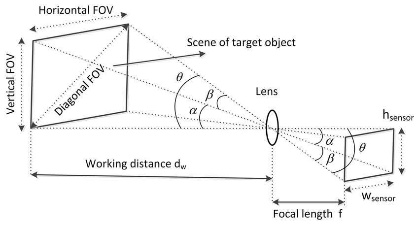
The focal length of a camera is the distance from the center of the lens to the focal points. If the focal points are closer to the lens center, it means the lens has more optical power to converge the light. The stronger the power, the wider field, and there is a mapping relationship between the Field of View and the focal length. Since the light is captured from the scene and cast to the image sensor in the same way, the triangles formed while the light enters and exits the lens are similar. Therefore, we can use the estimated field size and distance to calculate the focal length.
Twolenssystemcalculator
Field of View (FoV) usually refers to the field an image sensor captures. It is not a constant value because further scene results in a larger captured field. Therefore, FoV is usually represented in angles of view – the larger, the wider. The lens casts an image circle while the sensor captures a rectangular section, so the native FoV of the lens is different from the field the sensor captures. Most times, the sensor crops a rectangular section inside the image circle. For the fisheye lens, the image circle is totally inside the rectangle so that the sensor captures the whole cast field.
The light cast to the image sensor forms a circle of light, also known as the image circle. Most times, we want the image circle large enough to shed light on the whole image sensor, otherwise, we will see dark areas on the edges of the image. However, for some fisheye lenses, we want the whole image circle inside the image sensor frame so that we never miss any detail of the whole 180-degree hemisphere.
The focal length of a lens indicates its ability to converge light, and it’s measured by the distance between the lens center and focal point. The shorter the distance is, the more sharply it bends the light, and the larger field it’ll be able to squeeze into its image circle. As M12 lenses are made up of several pieces of glass (or plastic), the term “effective focal length (EFL)” is used to present this ability.
Reliable and accurate testing methods are essential to guiding the polishing process during the figuring of optical telescope mirrors. With the natural advancement of technology, the procedures and instruments used to carry out this delicate task have consistently increased in sensitivity, but also in complexity and cost. Fortunately, throughout history, the Foucault knife-edge test has shown the potential to measure transverse aberrations in the order of the wavelength, mainly when described in terms of physical theory, which allows a quantitative interpretation of its characteristic shadowmaps. Our previous publication on this topic derived a closed mathematical formulation that directly relates the knife-edge position with the observed irradiance pattern. The present work addresses the quite unexplored problem of the wavefront’s gradient estimation from experimental captures of the test, which is achieved by means of an optimization algorithm featuring a proposed ad hoc cost function. The partial derivatives thereby calculated are then integrated by means of a Fourier-based algorithm to retrieve the mirror’s actual surface profile. To date and to the best of our knowledge, this is the very first time that a complete mathematical-grounded treatment of this optical phenomenon is presented, complemented by an image-processing algorithm which allows a quantitative calculation of the corresponding slope at any given point of the mirror’s surface, so that it becomes possible to accurately estimate the aberrations present in the analyzed concave device just through its associated foucaultgrams.
You do not have subscription access to this journal. Cited by links are available to subscribers only. You may subscribe either as an Optica member, or as an authorized user of your institution. Contact your librarian or system administrator or Login to access Optica Member Subscription
In an ideal case, the lens optical format would equal the sensor format, where the sensor’s diagonal equals the image circle’s diameter, so the diagonal field of view of the sensor (DFoV) equals the native FoV of the lens.
Jesús Villa, Gustavo Rodríguez, Ismael de la Rosa, Rumen Ivanov, Tonatiuh Saucedo, and Efrén González J. Opt. Soc. Am. A 31(12) 2719-2722 (2014)


 Ms.Cici
 8618319014500