
Baby SonoShow 2D/3D/4D/5D and Gender Ultrasound - 3d ultrasound las vegas
Integrated frequency conversion with massive bandwidth. Leveraging groundbreaking developments within diode laser technology and photonic integration.
To apply the lens MTF correction, check the Apply sensor MTF compensation checkbox in the compensation window, shown above.
Cardboard Camera Obscura · Step 1: Step 1: Gather Your Materials · Step 2: Step 2: Cut Out Your Cardboard Pieces · Step 3: Step 3: Tape Your Cardboard Pieces · Step ...
The lines shown in blue are saved to a file, which should have a txt or CSV extension. (If the text isn’t in the clipboard, you can select and copy it.) Only the first line (-0.00968, 0.04781) contains data. The rest consists of comments that you can use to verify that you have the correct settings.
Shipping Policy | Privacy Policy | Return Policy | Imatest Terms and Conditions
We receive frequent requests from customers who want to measure lens MTF, and it’s always disappointing to tell them Imatest measures system MTF, which includes the effects of the image sensor, and not lens MTF. While sensor MTF can be removed by deconvolution, i.e., the same division process (in frequency domain) used to compensate for the chart MTF, reliable sensor MTF data is difficult to obtain. But even without exact sensor MTF data Imatest can do a partial (approximate) correction for the sensor MTF.
Chart-compensated MTF model – Chart MTF is measured in units of Cycles per Object mm from a printed edge (appropriately slanted for the measurement), then fit to a simple equation that fits a wide range of chart MTF measurements.
Using chart compensation is somewhat more error-prone than not using it. You need to check settings carefully. Make sure
State Select an option... Australian Capital Territory New South Wales Northern Territory Queensland South Australia Tasmania Victoria Western Australia
modulation transfer function中文
Starting in Imatest 5.1 the effects of the chart can be reduced by dividing the measured MTF by MTFchart-projected, which is equivalent to deconvolution in the spatial domain. We can also calculate the approximate lens MTF by dividing measured MTF by a geometrical model of MTFsensor, which we use because (A) reliable measurements of MTFsensor are difficult to obtain, and (B) results are closer to lens MTF than you can get without the correction.
Convolution and deconvolution – The response of a linear system can be calculated by convolving its components. Convolution is a complex operation— as its name implies— but when response is converted into frequency domain (by means of a Fourier transform), it becomes simple multiplication. The measured response (Modulation Transfer Function = MTF) of an imaging system is the product of its elements:
Imatest can correct for the geometrical component of lens MTF in cameras without anti-aliasing filters. Before you apply this correction, you should find out if your camera has one. Most DSLR and mirrorless interchangeable cameras made before 2015 have them. Since 2015 a number of cameras have small enough pixels (sufficient megapixels) to dispense with them with minimal risk of Moiré. Since removing the AA filter significantly improves camera sharpness (beyond the simple megapixel increase) it may be mentioned in the camera specifications and in reviews. For example, see Wired’s review of the Panasonic GX85.
Supplied with a 20mm corrugate conduit gland this allows for the best protection of the actuators cable without any modifications required to the structure. If required it could be replaced with a typical cable gland.
With the built in and adjustable open and close position stops allow for the simplest and easiest setting of the open and close swing angles, completely adjustable they allow for forward/back slide movement and are tightened with a spanner to lock against the cast in bite points.
mtf光学
Alpha Automation is dedicated to providing excellence with over 18 year of automation experience using the highest quality equipment and uncompromised support you can rest assured that your in the best hands. All products sold by Alpha Automation are backed by Australian warranty and lifetime technical support if needed down the track.
Adimec has a page, CCD vs. CMOS – Modulation Transfer Function (MTF) in NIR, that explains why Sensor MTF is generally worse than the theoretical sinc(πf/(2 fNyq)) model, especially for small pixels and Near Infrared (NIR) wavelengths (> 700μm). It has a plot of MTF at the Nyquist frequency vs. wavelength for two Sony sensors with relatively large pixels, the ICX674 (4.54μm pixels) and IMX174 (5.86μm pixels). MTF is relatively constant and close to the theoretical value of 0.6366 below 700 nm. The method used to obtain this plot is not stated.
The versatile swivel tail system allows for flexible mobility in the gates travel which is seldom seen in the design of the actuator and the bracketing system is supplied at full size ready to cut down and weld to suit most installation geometries.
*The first key value line contains all information required for the Chart Compensation file. The second line (MTF50 in Cycles/Object mm) is included for reference— for conveniently comparing chart sharpness.
For these three modules the chart should be measured carefully. The measurement is entered on the right of the Settings window.
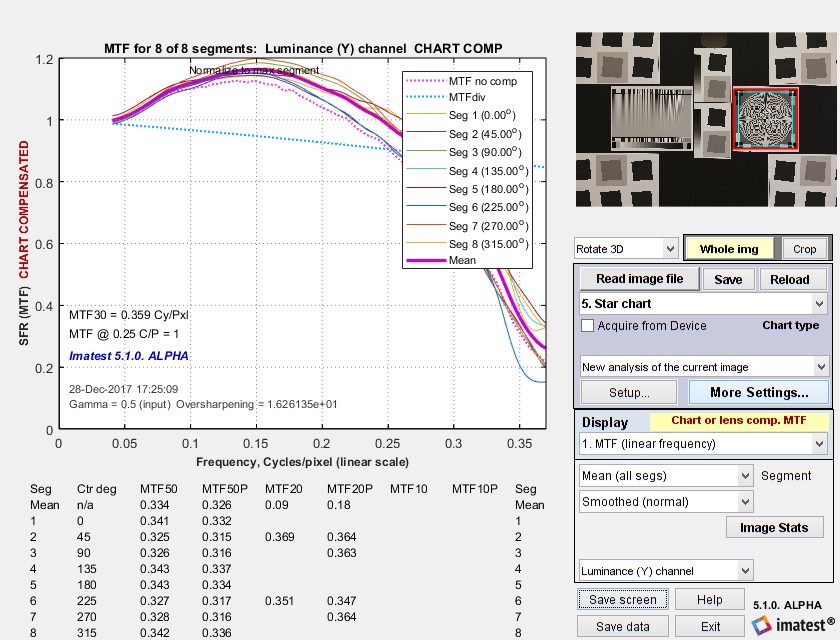
MTF compensation increases measured MTF values at high spatial frequencies. This often means that noise as well as the signal will be boosted. This is very visible in the above image, taken with a Canon EOS-6D DSLR, which has an anti-aliasing filter that removes most response above Nyquist (~3600 LW/PH). What is left is primarily noise.
\(\displaystyle MTF_{sensor} =\frac{ \sin \frac{\pi f}{2 f_{Nyq}}}{ \frac{\pi f}{2 f_{Nyq}}} = \text{sinc} \frac{\pi f}{2 f_{Nyq}}\) where fNyq = Nyquist frequency = 1/(2 pixel pitch).
When the chart is imaged (projected) on the sensor, the projected chart MTF is calculated by transforming the chart frequency units to the native sensor units (Cycles/Pixel) using
Chart MTF is measured from images of slanted-edges on various media (inkjet paper, photographic paper, B&W or color film, or Chrome on Glass) at the same contrast (usually 4:1 or 10:1) used for testing lenses. These media are both transmissive and reflective and have a wide range of sharpness.
MTFchart-projected (the chart MTF projected on the image sensor) is not really a part of the imaging system, so we’ve dealt with it by recommending that charts be used in conditions (low magnification) where MTFchart-projected stays close to 1 in the frequency range of interest. Since our recommendations have been conservative the results have been “good enough” in most instances.
MTF
Furthermore the AXO 5024 is a compact design of only 100mm in width, 123mm in height and an overall length of 1180mm keeping it discreet.
No information is available for this page.
In dentistry various types of laser are used - Click here to discover all types of diode lasers!
Get your Modified Mastering Microbiology with Pearson eText -- Standalone Access Card -- for Microbiology with Diseases by Body System here today at the ...
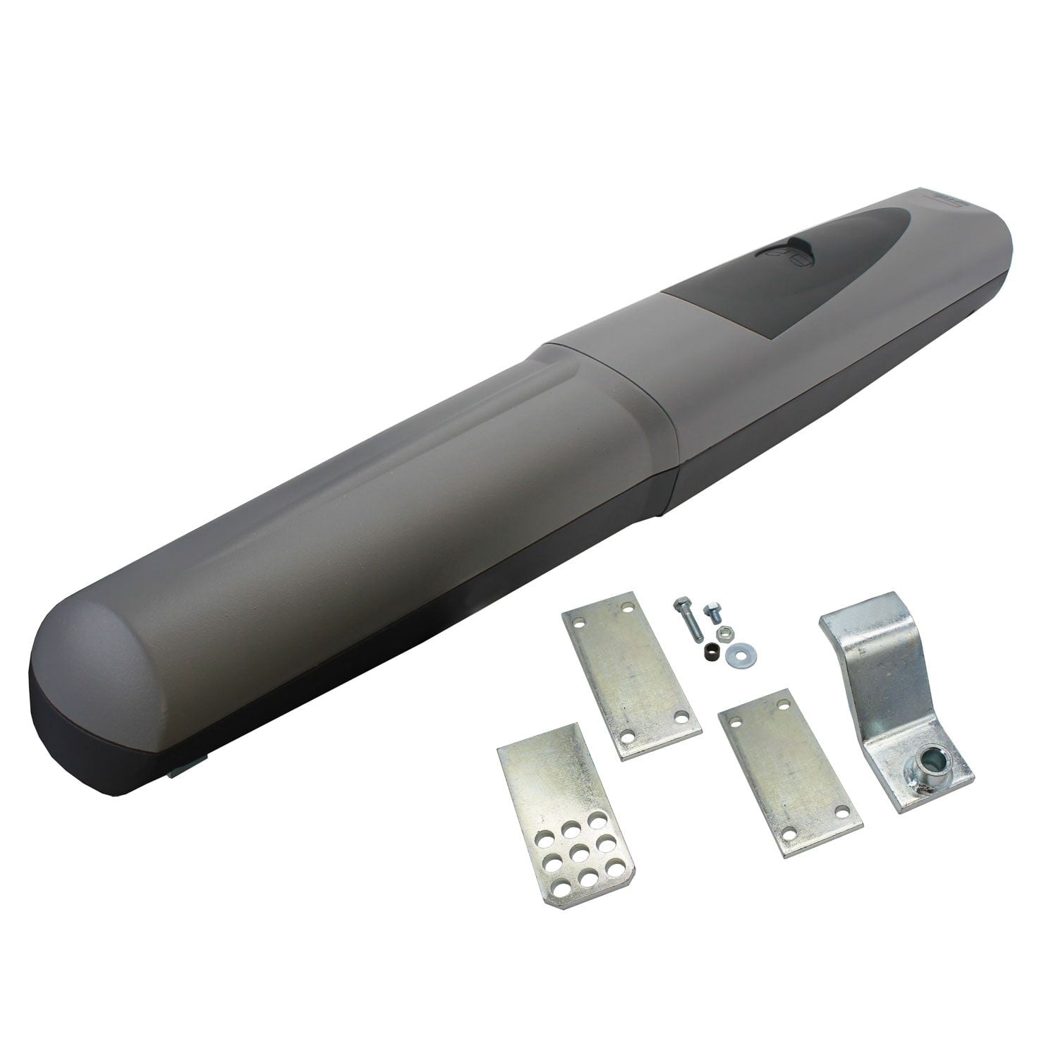
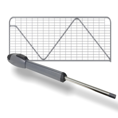
The Axo series Linear Actuator is a high torque, high duty cycle encoder controlled motor. Extremely strong it can be used from short gate installations as well as a complete driveway gate up to 5m in length/1000KG in weight. With the Axo’s wind tolerance and higher torque it can even be used with clad/covered gates in conjunction with an electric lock.
If you need help or cant find what your looking for or just unsure which product best suits your requirements why not give one of friendly and professional staff a call on:
Click on a link in the table to download the chart compensation file for the indicated media type. Save the file to any convenient location. (We recommend the Imatest Resources folder, which can be located by pressing Open resources folder in the Chart and sensor MTF compensation or Options II menu.) Although the files contain several lines, only the numbers in the first line (the first line of Key values in the table below) are used for chart compensation. The remaining lines contain annotations (the file used for the calculation, the chart MTF50, etc.) Some of the data is relatively old: we will be taking new measurements.
The actual calculation (details below) is performed with files that contain parametric fits to the measured data for the specific media type and printing technology. Applying chart compensation will improve the consistency of MTF measurements taken on different test charts.
SensorMTF
If required there is an optional battery backup system available which will fit directly into the systems control box allowing for uninterrupted operation.
L'identité du père du futur bébé de Morgane (Audrey Fleurot) reste un mystère entier pour le moment ➡️ https://l.programme-tv.net/JP1 ... HPI - Série is with ...
In Imatest sharpness modules, pixels/mm is typically derived from the user-entered value of pixel pitch (in μm), where pixels/mm = 1000 / (pixel pitch (μm)). Magnification is either entered in the settings window or derived from geometrical factors (like the bar-to-bar spacing in SFRplus or the vertical registration mark spacing in eSFR ISO). We use MTFdiv(f) and MTFchart-projected(f) interchangeably because the measured camera MTF (MTFmeasured) is divided by MTFdiv to obtain the compensated (more accurate) measurement.
LensMTF
Starting with Imatest 5.1 you can compensate MTF measurements for chart sharpness. Compensation is available in all slanted-edge modules (SFR, SFRplus, eSFR ISO, SFRreg, and Checkerboard), and for Star, Random (Dead Leaves, Spilled coins, etc.), and Log F-Contrast. Applying chart compensation requires care.
If MTFdiv at the Nyquist frequency (fNyq = 0.5 C/P) is lower than 0.9 (90%), measurement accuracy can be improved by dividing the measured MTF by MTFdiv. If MTFdiv(fNyq) is greater than 0.9, there is very little improvement.
Introduction | Calculation | MTF compensation files | Applying the compensation Sensor MTF compensation | Chart MTF measurements
A recent reference to sensor MTF is Interferometric Measurement of Sensor MTF and Crosstalk (2017) by T. Georgiev, et. al. of Qualcomm, presented at the Electronic Imaging 2017 conference. They used a Ximea MQ013RG-E2 sensor, which has 5.3μm pixels.
Lens MTF measurements – Imatest traditionally measures the MTF of the entire system, lens + sensor + image processing, but a number of customers are interested in measuring the MTF of the lens alone. To do so, the effects of the sensor and image processing must be removed. It’s easy to minimize image processing by converting files from raw using LibRaw (for commercial files) or Generalized Read Raw (for binary files), but removing the effects of the image sensor is more difficult. Although exact measurements of sensor MTF are difficult to come by (as of early 2018) we can get a reasonable approximation for many situations (visible light, moderate pixel size) using a simple theoretical equation for geometrical sensor MTF:
You can create an MTF compensation file using the technique described below in Appendix: Chart MTF measurement. This file should be saved with a descriptive name to any convenient location (though we recommend the Resources folder).
Oct 24, 2024 — Plane polarized light consists of waves in which the direction of vibration is the same for all waves. In circular polarization the electric ...
Modulation transfer function
In the case of a power outage, simply slide open the cover and using the supplied key you can release the actuator. Once release you can open and close the gate by hand until ready to re-lock.
Typically a linear actuator is a rigid unit and has very little tolerance for up-down movement in the gate however with the swivel system there is now some allowance, typical scenarios that would utilize the swivel would be gates with a support wheel, gates with a slight sag or gates with misaligned hinges. Note that this will not support rising gates.
Here is a typical example, run in Rescharts for a Star chart image. Indicators appear in the y-label, title, and on the middle-right of the Rescharts window. The compensation file name (media type) does not yet appear. Two additional curves appear on the plot. The original MTF without compensation appears as a Magenta dotted line ………..The projected MTF of the chart (MTFchart-projected ) is a cyan dotted line ………..
For this equation to be valid the sensor must not have an anti-aliasing filter (OLPF) and a raw image must be used (converted with LibRaw or Read Raw). JPEG images from cameras inevitably have signal processing (sharpening and noise reduction) that throws off the results. This approximation is reasonably good for visible light, but poorer for Near Infrared (NIR), where electron diffusion in the silicon degrades the MTF.
Super Duty High Torque Linear Actuator with Encoder and Limit Stops The Axo series Linear Actuator is a high torque, high duty cycle encoder controlled motor. Extremely strong it can be used from short gate installations as well as a complete driveway gate up to 5m in length/1000KG in weight. With the Axo’s wind tolerance and higher torque it can even be used with clad/covered gates in conjunction with an electric lock. Furthermore the AXO 5024 is a compact design of only 100mm in width, 123mm in height and an overall length of 1180mm keeping it discreet. The versatile swivel tail system allows for flexible mobility in the gates travel which is seldom seen in the design of the actuator and the bracketing system is supplied at full size ready to cut down and weld to suit most installation geometries. Adjustable Limit Stops With the built in and adjustable open and close position stops allow for the simplest and easiest setting of the open and close swing angles, completely adjustable they allow for forward/back slide movement and are tightened with a spanner to lock against the cast in bite points. Complete Alloy bodied with a stainless steel lead screw allows for its superior high torque delivery. Built In Encoder Undisputedly the best technology the encoder motor is standard and will feedback to the system where the gate motor and effectively the gate is in its travel through the entire cycle. Allowing for reliable operation regardless of any changes in operation be it due to temperature, wind or other factors. This is the technology you can rely on for constancy and peace of mind. Swivel System Typically a linear actuator is a rigid unit and has very little tolerance for up-down movement in the gate however with the swivel system there is now some allowance, typical scenarios that would utilize the swivel would be gates with a support wheel, gates with a slight sag or gates with misaligned hinges. Note that this will not support rising gates. Conduit Feed Supplied with a 20mm corrugate conduit gland this allows for the best protection of the actuators cable without any modifications required to the structure. If required it could be replaced with a typical cable gland. Manual Release System In the case of a power outage, simply slide open the cover and using the supplied key you can release the actuator. Once release you can open and close the gate by hand until ready to re-lock. If required there is an optional battery backup system available which will fit directly into the systems control box allowing for uninterrupted operation. Installation Geometry Actuator Dimensions Specifications Maximum Gate Length5mMaximum Gate Weight1000KGMaximum Opening Angle110°EncoderYesMotor Power (Volts)24V DCPower (Watts)120WOperating Temperature-20° to +55° CStroke600mmThrust (N)4500N MaxDuty Cycle100%
We plan to supply MTF compensation files in Imatest builds. They will also be available for downloading in the Reflective charts and Transmissive charts quality pages.
mtf是什么
Single Infrared Beam Sensor · Based on 0 reviews · Related products · High Range Wireless Alarm Repeater/Signal Transfer(DES-A08) · High Range Wireless Alarm ...
by K Tejchman · 2021 · Cited by 93 — Oxidative damage leaves a mark, which can be detectible by specific methodology regarding affected molecules. Those substances become the biomarkers of ...
Another very interesting mineral to fluoresce with a 405nm laser is the daylight fluorescing hyalite opal from Mexico. This opal actually fluoresces best under ...
mtf群体
Undisputedly the best technology the encoder motor is standard and will feedback to the system where the gate motor and effectively the gate is in its travel through the entire cycle.
Most users won’t be measuring chart quality themselves. They’ll use the measurement results in Chart MTF compensation files provided by Imatest in the above links. Those users can skip this section.
Imatest MTF measurements are affected by both chart and camera quality. Since its inception, Imatest has recommended test charts that are large enough to minimize the effects of the chart on camera MTF measurements. Although we have some descriptions of chart quality on the Chart Quality Index, Reflective charts, and Transmissive charts quality pages, these pages don’t have enough detail to determine the precise effect of chart MTF on camera MTF measurements, which is particularly important in situations where geometric constraints (test equipment and lab size, etc.) make it difficult to meet the chart recommendations.
These results should not be represented as true lens MTF. At best it’s approximate— closer to true lens MTF than measurements made without the correction, but definitely not all the way there.
-0.01664, 0.05207, Ver-R -0.01670, -0.04956, Hor-T end_data MTF50{Ver-R), measure:, 19.06, model:, 19.35, C/Obj mm MTF50{Hor-T), measure:, 20.34, model:, 20.54, C/Obj mm file, C:\imatest\Data\SFR\Misc\Chart_compensation\Sony download\Uncertain orientation\SFRplus_LVT_157mm_00019.JPG date_run, 12-Jan-2019 15:59:44 date_mod, 2018-11-05_17-46-40, (closest to capture) Magnification, 1 aperture 8.0 um_per_pixel, 3.88 Equation, MTF = exp(-x(1)*f-(x(2)*f).^2); f in cycles/object mm
If you do not already have Imatest Master, purchase or try a free trial of Imatest Master version 5.1 to use the MTF Compensation feature.
Allowing for reliable operation regardless of any changes in operation be it due to temperature, wind or other factors. This is the technology you can rely on for constancy and peace of mind.
To prevent excessive noise boost MTFchart-projected (the cyan dotted line ……….) must not drop too low (to 0.3) in the frequency range of interest.
MTFchart-projected is also called MTFdiv because it is used to divide MTFmeasured. The minimum value of the denominator must be greater than 0.3 because smaller values are unreliable and can cause an excessive noise boost. The frequency where projected chart MTF drops to 0.3 should be outside the range of interest for the measurement— above the Nyquist frequency fNyq .
State Select an option... Australian Capital Territory New South Wales Northern Territory Queensland South Australia Tasmania Victoria Western Australia


 Ms.Cici
 8618319014500