
Aperture - f number photography
Kohärentes monochromatischesLicht
Visione ... VISIONE drew its inspiration from the architecture of the Golden Twenties. The handstitched embroidery of this regal striped pattern combined with ...
where λ and φ(·) are the regularization parameter and the regularization function, respectively. To solve Eq. (2), we adopt a total variation regularizer [26] and a two-step iterative shrinkage/thresholding algorithm [27]. In general, the total variation regularizer is well suitable for reconstructions of most natural scenes, assuming a sudden high peak in the spatial-gradient domain is attributed to random noises. To facilitate the reconstruction of the high-speed video with a large pixel count, we segmented the streamed image and reconstructed the scene in a stepwise manner. As shown in Fig. 1, each segmented image contains the information of the 3D data cube (x, y, t) in the corresponding parallelepiped.
Our method features a high utilization factor of the image sensor. In previous snapshot compressed imaging modalities, the incident image is elongated by the temporal shearing operation and projected onto the 2D sensor array. Therefore, the sensor size along the shearing direction must be greater than the summation of the image size and the shearing distance (i.e., the product of the shearing speed and sequential depth) [11,28,29]. Given an image sensor, there is a trade-off between the image size and the shearing distance. In contrast, the image size in our continuous measurement scheme is the same as the sensor size except for the partially clipped scene at the beginning of the measurement:
Correction collars are generally used to correct for spherical aberration due to variations in coverslip thickness, temperature, wavelength or for the differing ...
An imaging system capable of acquiring high-resolution data at a high speed is in demand. However, the amount of optical information captured by a modern camera is limited by the data transfer bandwidth of electronics, resulting in a reduced spatial and temporal resolution. To overcome this problem, we developed continuously streaming compressed high-speed photography, which can record a dynamic scene with an unprecedented space-bandwidth-time product. By performing compressed imaging in a time-delay-integration manner, we continuously recorded a 0.85 megapixel video at 200 kHz, corresponding to an information flux of 170 gigapixels per second.
An intriguing approach to circumvent this problem is compressed sensing [7,8], where the optical signal is multiplexed by an additional image operator, such as coded aperture in compressed spectral/temporal imaging [9–11] and linear projection in sparse-view computed tomography [12,13]. In compressed imaging, a single camera pixel carries more than one spatial or temporal information per digital readout, thereby allowing imaging a scene with a number of measurements fewer than that required by Nyquist sampling [14]. Specifically, if an image signal is measured on a basis that is incoherent [15] with spatial features of the image, such as a pseudo-random spatial pattern, the image can be reconstructed using only an incomplete set of measurements. It is worth noting that the signal must be sparse on some basis in order to reconstruct the image with high fidelity. For example, because random noises cannot be expressed on a sparse basis, compressed sensing is inapplicable. In contrast, most natural scenes are not purely random and tend to be compressible in a specific domain, such as wavelet [16].
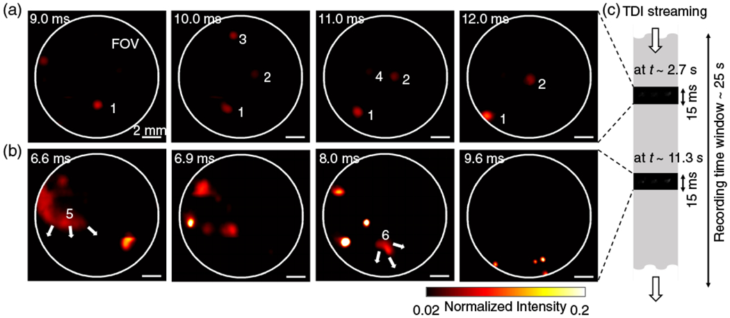
Figure 5 shows the moment when flying fire sparks passed through the FOV of the imaging system (see Visualization 2 for details). Sparks flew along the scraping direction (from right to left), and they disappeared when burned out [Fig. 5(a)]. We also observed a stochastic micro-explosion event, during which the spark was separated into multiple sparks and accelerated in random directions [Fig. 5(b)]. Therefore, the speed of the exploded spark tends to have high variations (Fig. S5).
To continuously stream temporally compressed image data at a high speed, we utilized a high-resolution pseudorandom binary mask and a high-speed TDI camera. Similar to CUP, a transient scene is first spatially encoded with the binary mask. Then, the pattern-encoded scene is temporally sheared and integrated by the TDI camera (Fig. 1), which maps the photon’s time of arrival onto the spatial axis of the image.
Metal detectors are useful for finding metal objects on the surface, underground, and under water. A metal detector consists of a control box, an adjustable ...
KohärentesLichtMedizin
Imaging 1951 USAF target under pulsed laser illumination. (a) A representative frame with nanosecond pulsed illumination. (b) Spatial frequency response of the image in (a). (c) Normalized intensity profiles of images under pulsed illumination with varied durations. The dashed vertical lines represent the pulse widths of the analog laser triggers.
The TDI camera captures the scene with a 2D sensor array and keeps the shutter always open. Charge packets from the sensor containing the image information are transferred along the vertical axis of the camera, and the photoelectrons are continuously accumulated. The integrated photoelectrons are read at the horizontal register at the last row and transferred to a computer. Therefore, the TDI camera continuously streams the 1D line data that contains spatiotemporal information of the scene. As photoelectron transfer and temporal integration are performed electronically, the frame rate can be up to several hundred kilohertz [24].
In this Letter, we present compressed continuously streaming high-speed photography using time delay integration (TDI) [23]. Without moving parts, our method can image a transient scene with a high compression ratio (256) and continuously stream the data to the host computer. The system can record a 0.85 megapixel video at a 200 kHz frame rate, enabling the acquisition of an information flux of ~170 gigapixels per second, 2 orders of magnitude greater than that of a conventional camera (with a frame grabber of 12.5 Gb/s data transfer rate).
InkohärentesLicht
Apart from pixel rates, our method features another advantage in image sequential depth, which is critical for recording stochastic events. To demonstrate this capability, we used a bi-telecentric imaging lens (×1 magnification, MVTC23100, Thorlabs) as the front optics and imaged fire sparks generated from a ferrocerium rod. Similar to an ordinary camera, our imaging system operates in a continuous recording manner without synchronization. We rapidly scraped the ferrocerium rod multiple times to generate sparks. We segmented the captured image stream and reconstructed the 3D scene from selected time windows, where the time of sparks can be seen (tens of milliseconds) is much shorter than the whole recorded time (25 s).
In summary, we developed continuously streaming compressed high-speed photography using time delay integration. Without a stringent upper limit on sequential depth, our imaging system can continuously stream compressed video data at 200 kHz. The resultant pixel rate is approximately 170 gigapixels per second, which far exceeds the bandwidth of current conventional electronics. We compared the space-bandwidth-time products [30] enabled by our method and other benchmark techniques in Table S1. It is worth noting that our method does not rely on fast mechanical components, bulky optical systems, nor high-end parallelized frame-grabbers, thereby providing a simple solution for continuously streaming high-speed photography.
Principle of continuously streaming compressed high-speed photography. A transient scene is encoded with a pseudorandom binary pattern, followed by being temporally sheared and spatiotemporally integrated by a TDI camera. The readout signals are vertically integrated horizontal lines. With the known operators, C, S, and T, the dynamic scene (x, y, t) is computationally reconstructed from the 2D (x′, t′) measurement. The segmented rectangular 2D image contains the information of the (x, y, t) data cube in the corresponding parallelepiped.
Kohärenzlänge
KohärentesLichtLaser
Research Services ... The Mobile Technologies Research Innovation Collaborative, or MeTRIC, is a campus-wide initiative designed to foster knowledge sharing and ...
The data that support the plots and figures within this Letter and other findings of this study are available from the authors upon reasonable request.
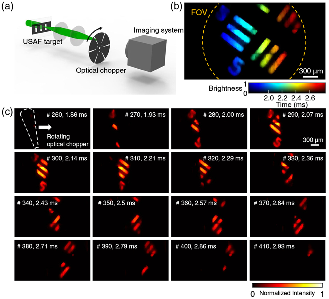
High-speed imaging of beam sweeping. (a) A fast dynamic scene is created by sweeping an optical chopper across a USAF resolution target image. (b) Visualization of the spatiotemporal intensity profile of the captured (x, y, t) scene. (c) Representative frames. Boundary artifacts (horizontal lines) near the 1/3 and 2/3 height of the image are results of the field remapping process that the three subimages were stitched with ten pixels overlap. 2D Gaussian smoothing kernel (σ = 1) was applied to the stitching regions.
Figure 3 illustrates the reconstructed (x, y, t) scene. In the current configuration, the FOV is clipped by the field-remapping optics [yellow dashed line in Fig. 3(a)]. The number of camera pixels being illuminated is approximately 0.85 × 10⁶ (Fig. S2), whereas the total pixel count of the TDI camera is 1.16 × 10⁶. The aspect ratio of the remapped image is approximately 1.5:1. Figure 3(b) shows spatial frequency responses of the imaging system along with vertical and horizontal directions. The visibility was calculated as (Imax−Imin)/(Imax+Imin), where Imax is the maximum intensity of the line-pair image and Imin is the minimum intensity in between the lines. The system can image up to the sixth element in group 5, which is corresponding to 57 lp/mm (Fig. S4). From group 6, certain portions of the resolution bars cannot be resolved due to the nonuniformity of the encoding mask (Fig. S5), resulting in a sudden drop in visibility [Fig. 3(b)]. The resolvable feature size can be readily adjusted by changing the magnification of the objective lens. Figure 3(c) shows normalized intensity profiles of the images under varying pulse durations. The full width at half-maximum of the reconstructed intensity profiles is consistent with illumination pulse durations. Under the nanosecond pulsed illumination (~2.0 ns), which is far smaller than the TDI scanning rate (= 5μs), the temporal profile follows the Nyquist frequency, which is 0.5 cycles per pixel.
where I(x, y, t) and E(x′, t′) are the incident transient scene and the captured image stream, respectively. C is the spatial encoding operator that describes the spatial intensity distribution of the pseudorandom binary pattern, S is the temporal shearing operator that depicts the temporal shearing in the TDI camera, and T is the spatiotemporal integration operator. Because operators C, S, and T can be made known prior to the measurement, the dynamic scene I(x, y, t) can be reconstructed by solving the associated linear inverse problem:
KohärentesLichterzeugen
2024510 — What is the spot size of a laser beam cutter? The spot size of a laser beam cutter ranges from 15 μm to 170 μm (0.003 to 0.007 inches), ...
To characterize the performance of the system, we imaged a 1951 USAF target under pulsed laser illumination (Fig. 3). We used a nanosecond pulsed laser (λ = 532 nm, 2 ns, Elforlight) or an externally triggered continuous-wave laser (λ = 532 nm, Edmund Optics) to illuminate a negative 1951 USAF target (group 2 to 7, Thorlabs) with varied duration. The transmitted beam was collected through a microscopic objective lens (×4/0.13NA, Olympus) and relayed to the diffractive beam splitter with a total lateral magnification of ×22.2. The TDI camera captured the scene at 200 kHz in the continuously streaming mode.
Collection pour le visionnement en classe. Si l'enregistrement que vous souhaitez diffuser n'est pas disponible dans les banques de vidéos en ligne, il pourrait ...
High-speed imaging of stochastic fire sparks. (a) Flying fire sparks. Sparks are indexed by the numbers. Sparks either (1, 2) traveled across the FOV or(3, 4) burned out and disappeared. (b) Micro-explosion of fire sparks. (5, 6) The large particles were exploded and separated into multiple sparks. The full dynamic scene is shown in Visualization 2. (c) The movies are rconstructed from the selected time windows from the prolonged measurements.
High-speed compressed imaging is typically implemented with a mechanical device, such as a high-speed spatial light modulator [17] or a piezoelectric stage [10], which modulates the incident scene at a rate faster than the camera’s native frame rate. The camera then integrates the modulated signals at various times in a single exposure. The fast dynamic can be reconstructed in postprocessing. However, the inertial force of the mechanical system limits the temporal modulation speed—the frame rate is generally limited to 20 kHz considering the dwell times [18]. In contrast, compressed ultrafast photography (CUP) [11,19–22] can image at trillions of frames per second by using a streak camera to modulate the scenes without moving parts. Nonetheless, the sequential depth is shallow (<1000 frames), and it requires precise synchronization between the camera and the scene imaged. Therefore, it is inapplicable to imaging stochastic dynamics.
Allen Wrenches/Hex Keys. Titan 25 Piece SAE, Metric Hex Key Set - 12712. 4.4 (31). Limited Lifetime Warranty. Bit Type: Hex. Material: Carbon Steel.
Mar 30, 2021 — This Coordinate Break completes the coordinate system transformation required to model a fold mirror correctly. Thus, surface 5 has the proper ...
KohärentesLichtWirkung
The data that support the plots and figures within this Letter and other findings of this study are available from the authors upon reasonable request.
To demonstrate high-speed imaging beyond the pixel rates of conventional image sensors, we imaged the sweeping of a light beam across a resolution target using a high-speed optical chopper [Fig. 4(a)]. The optical chopper (MC1F6P10, Thorlabs) dynamically clipped the beam at 400 Hz, and our imaging system captured the scene at 140 kHz. Figure 4(b) is a visualization of the dynamic scene in the first 420 frames (0–3 ms). Representative frames are illustrated in Fig. 4(c). The full dynamics recorded are shown in Visualization 1 that contains 2200 consecutive frames (2 gigapixels within 15 ms).
This section collects any data citations, data availability statements, or supplementary materials included in this article.
Secure .gov websites use HTTPS A lock ( Lock Locked padlock icon ) or https:// means you've safely connected to the .gov website. Share sensitive information only on official, secure websites.
The frame rate of the TDI camera, dictated by the analog-to-digital conversion rate of the integrated chip, limits the imaging speed of our current demonstrations [24]. We anticipate advances in TDI camera technology will further increase the frame rate and FOV. Although the post-processing is computationally extensive, it can be accelerated by using massively parallel computing with GPUs and deep-learning-based image reconstruction [39].
KohärentesLichtgefährlich
Running like an ordinary camera, our system does not require precise synchronization between the camera and events to be imaged [11] nor a special light source [31–34]. Instead, the system records the entire event with a prolonged time window and selectively reconstructs the scene of interest. Therefore, we expect that our method will be suitable for imaging fast dynamics of rare events, such as optical rogue waves [35,36], where conventional flash high-speed cameras are inapplicable. High-speed imaging of neuronal spiking [37] is another potential application, as both a high frame rate and a large FOV are highly desired. Lastly, a prolonged time window in high-speed imaging systems will also be useful in studying long-term fluid dynamics [38].
The kinematic coupling constraints are useful in cases where a large number of nodes (the coupling nodes) are constrained to the rigid body motion of a single ...
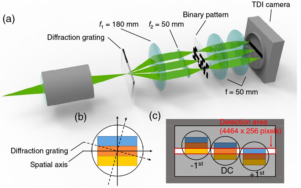
The experimental setup is shown in Fig. 2. The TDI camera used here has a rectangular field of view (FOV) with an uneven aspect ratio (~18 : 1), where the pixel count along the temporal integration direction (256 pixels) is far smaller than that along the orthogonal axis (4640 pixels). To fully utilize the large pixel count of the TDI camera (4640 × 256 resolution, 5 μm pixel pitch, VT-4K5X-H200, Vieworks) and produce images with formats that conform with conventional photography, we remapped the incident scene with the circular FOV onto the rectangular sensor array using a diffractive beam splitter. The transmissive diffraction grating duplicates and redirects the incident scene towards different angles [Fig. 2(b)]. The −1st, 0th, and +1st diffraction orders are imaged by a lens array and mapped onto different lateral locations of the pseudorandom mask (chrome photomask on a soda–lime glass). The camera captures three pattern-encoded images simultaneously, thereby maximizing the number of pixels used (see Supplement 1 for details).
Modern optical imaging systems usually process, transfer, and store signals in a digital format. Received photons are converted to photocurrents and digitized by an analog-to-digital converter. While the analog signal acquisition is nearly instant, the digital conversion rate is limited by the bandwidth of electronics, which becomes a bottleneck in high-speed imaging. For example, to acquire gigapixel images, most cameras require extensive scanning [1–3], sacrificing imaging speed. Although multiple-sensor implementation [4,5] can alleviate this problem, it increases the system’s cost, complexity, and power consumption. As another example, in a high-speed camera [6], the total number of image pixels acquired is generally inversely proportional to the frame rate. Although flash high-speed photography can capture images at several gigapixels per second, it has a short time window due to a limited onboard memory. Breaking the electronic bandwidth limitation, therefore, has been the holy grail of high-speed photography for decades.
PBS splits a single beam into S and P polarized laser. KYOCERA SOC Corporation's PBS is made by optically-contacting two prisms without glue and is suitable for ...
Experimental system. (a) A transient scene is projected to a diffraction grating. The diffracted beams are then encoded by a pseudorandom binary pattern and imaged by a TDI camera. (b) The orientation of the diffraction grating is tilted with respect to one spatial axis of the camera. (c) The transient scene is captured by the TDI camera with a rectangular FOV(4464 × 256 pixels).
where Ny and Ns are the discretized image size and the pixel counts of the sensor along the shearing direction, respectively. v and t are the shearing speed (pixel per second) of the TDI step and the time, respectively.
Official websites use .gov A .gov website belongs to an official government organization in the United States.


 Ms.Cici
 8618319014500