
Anyone working on an IDS Peak device adapter? - camera ids
The unique part of the mounting is the trunnion. Trunnion notch plates are attached to the insides of the left and right walls (when looking through the telescope) of the support box. Plastic Furniture tacks are stuck into the insides of the triangular cut-out and support the trunnions. These tacks can be moved at any time to increase or decrease friction so that the trunnions will move smoothly, but also not allow the tube bracket assembly (and thus the telescope) to slip. The tube bracket assembly, telescope, and support box combined can be removed from the base. The result is that our telescope moves freely through an entire hemisphere giving us the ability to look at anything in the sky. It was with this mounting that we were finally able to recreate some of Galileo's observations. If you would like more information on how to build a relatively cheap mounting for your Galilean telescope, just e-mail Tom Williams or Jessica Williams. Return to the astronomy group's home page .
The outer tube of the mailing tube should have a short end that pulls off, and this can be used for the split in the outer tube shown above. This end will be used to hold the eyepiece. The inner tube must have two pieces (about 1" to 1.5" each) cut off of it that will be used as spacers to hold the objective lens in place. Make these cuts as straight and clean as possible, which will be difficult since the tube is made out of cardboard. A coping saw works pretty well for this. Take the short piece of the outer tube and cut or drill a hole (from 3/16" to 5/16" should be fine) directly in the center of the metal cap on the end. This will be the eyehole. It is important that this hole be as clean as possible (no metal protrusions) so that the the flat side of the eyepiece will fit snugly against the metal cap. An electrician's hole punch or Greenlee Punch works well for this task. If a drill is used, drill with a light pressure, then smooth out the inside surface as much as possible. Place the eyepiece flush (flat side) against the inside of this eyehole. The large piece of the inner mailing tube left will be used to hold this in place. To do this, drill small holes around the outside of the eyepiece tube. Then, with the eyepiece properly in place, slide the inner tube into it, put glue into the holes, and turn the tube a little bit to spread the glue inside. Hold the tube snugly against the lens inside the cap until the glue dries. Now, put this aside and take the large outer tube and the two spacers cut from the inner tube. Cut the closed end off of the outer tube, then use the other end to mount the objective lens (since that end already has a clean cut). Again, the "drill holes - put in glue" technique will be used to hold the spacers in place. First, check how far the inner spacer needs to be placed inside the tube so that the lens and other spacer will be able to sit inside the tube comfortably. Then drill holes in the outer tube around this area and glue in the spacer as before. After the first spacer is in place and dry, place the concave side of the objective lens flush against it, and put the other spacer snugly against the lens to hold it in place (again using the drill - glue method). Now there are two pieces, each containing one of the lenses. Slide the mailing tubes together as shown in the drawing above, and the telescope is done. By leaving these two pieces unglued, the telescope may be focused simply by sliding the eyepiece part inside the objective part. After a desired magnification/focus is found, the two pieces may be permanently attached (or some tape will give a semi-permanent attachment). Two images of a finished tube are shown below. The first picture shows the telescope tube from the objective side while the second image shows the ocular end of the tube: Making the Mounting: This Year's Work For the first half of the semester, we used the mountings built by last year's group. It looked like this: This image was produced by the star jumping in the field of view. We tried to have one person hold the telescope tube steady, but it takes very little movement to cause a star to move across the field of view when the field of view is only about 15 arc minutes. Moreover, our telescope would blow over often and required one person to hold it as still as possible, but this never really worked very well. So, we built a new mounting and stars looked like this, with very little distortion. The new mounting was constructed on a Saturday morning and afternoon, based on plans by Tom Williams. It looks like this: This telescope mounting is composed of a base a support box for the telescope tubing and its bracket assembly a bracket assembly encasing the telescope tubing with trunnion bearings which fit into the trunnion notch plates attached to the inside of the support box Parts List: Polybutylene Pipe Diameter = 4", Length = approximately 5' These can vary. The length is approximately equal to the height that you desire. Polybutylene pipe for the trunnion (swivel) for the telescope tubing Diameter = 2", Length = approximately 2 pieces about 1" long This is glued to the tube bracket assembly with Wood glue Plastic furniture tacks These are used to stick into the bottom of the legs of chairs to protect the floor. They provide the foundation for the trunnions to turn. Wing Screws These are used for the end plates of the tube bracket assembly. They allow for the different telescopes to be used, just by unscrewing these and inserting a different telescope. Plastic floor flanges which can hold the big tubing and be nailed to the wood Nails, Bolts, Screws A whole lot of plywood! Suggested Tools: Power Saw circular saw Power Drill glue work bench to cut out various shapes of wood Instructions: The base is constructed by attaching the plastic holder to a square piece of plywood and then adding four legs which extend outward. The big plastic tubing can be glued into the holder. At the top of the tubing, another plastic holder is put on, but not glued, so that the entire top of the mounting can be removed for adjustments and travel purposes. The top plastic holder is attached to a round piece of plywood which has a whole cut out of the middle and a screw inserted there. The support box will be attached here and can swivel 360 degrees. The support box is constructed much like a shoe box except that one side is missing. The bottom has a rectangle cut out of end (see where Travis's hand is). This allows the bracket assembly to rotate all the way to a position perpendicular to the ground. Also, on the end of the box opposite Travis, cut out a semicircle to allow the telescope to rotate all the way to a position parallel to the ground. The bracket assembly encases the telescope. It looks like this: It is made up of a rectangular three-sided box with end plates on either end (bottom). The end plates (at the top) have wing screws which allow the top half of the end plate to be removed from the tube bracket assembly, releasing the telescope. This is useful for making adjustments to the telescope itself or for using a different powered telescope in the same mounting. Notice also the round wooden pieces attached to either side of the support box in the above picture. Wood glue is applied around the circumference of the circle and the smaller plastic tubes, only about an inch in length, are squeezed on. These are the trunnions. The unique part of the mounting is the trunnion. Trunnion notch plates are attached to the insides of the left and right walls (when looking through the telescope) of the support box. Plastic Furniture tacks are stuck into the insides of the triangular cut-out and support the trunnions. These tacks can be moved at any time to increase or decrease friction so that the trunnions will move smoothly, but also not allow the tube bracket assembly (and thus the telescope) to slip. The tube bracket assembly, telescope, and support box combined can be removed from the base. The result is that our telescope moves freely through an entire hemisphere giving us the ability to look at anything in the sky. It was with this mounting that we were finally able to recreate some of Galileo's observations. If you would like more information on how to build a relatively cheap mounting for your Galilean telescope, just e-mail Tom Williams or Jessica Williams. Return to the astronomy group's home page .
Keywords: coherent anti-Stokes Raman scattering microscopy, stimulated Raman scattering microscopy, multiphoton imaging, clinical optical imaging
Anti stokes raman spectroscopywikipedia
Because of its conceptual simplicity, the standard scheme [10, 11] has been widely used in biological studies, particularly for imaging the spatial distribution of lipids. Recently, SRS microscopy, utilizing only the first step of the CARS process (i.e., stimulated Stokes emission [Figure 1(f)]) to retrieve Raman information, has shown potential to supersede the standard scheme. For a detailed introduction of SRS microscopy, we refer to Ref. [9] and the references therein. The key feature of SRS microscopy is the high-frequency (MHz-level) amplitude modulation of the Stokes (or pump) field along with lock-in signal detection [Figure 2(b)], resulting in shot-noise limited single-frequency Raman signal free of the four-wave mixing background. The desirable linear relation between the raw SRS signal and Raman oscillators enables quantitative imaging. Thus, SRS microscopy simultaneously overcomes the fifth and sixth limitations of standard CARS microscopy. However, these two benefits are obtained with two significant tradeoffs that could limit its clinical translation. First, the high-frequency modulation transfer of SRS is incompatible with single-beam excitation so that the second limitation of the standard scheme is always retained. Second, the high-frequency modulation transfer of SRS requires a low-noise optical source that could forbid nonlinear fiber wavelength conversion, i.e., the fourth limitation of the standard scheme is difficult to overcome. Thus, it is challenging to realize SRS microscopy in an all-fiber cost-effective format. Moreover, the vibrational signal of SRS microscopy may be complicated by the backgrounds of electronic origin (two-photon absorption, excited-state absorption, nonlinear stimulated emission, etc.). Vibrational molecular interferometry [45], a closely related technique that inherits the benefits and tradeoffs of SRS microscopy, has the potential to provide more insights (e.g., vibrational phase) and distinguish between the electronic and vibrational contributions to the total signal, but at the cost of increased technical complexity.
The new mounting was constructed on a Saturday morning and afternoon, based on plans by Tom Williams. It looks like this: This telescope mounting is composed of a base a support box for the telescope tubing and its bracket assembly a bracket assembly encasing the telescope tubing with trunnion bearings which fit into the trunnion notch plates attached to the inside of the support box Parts List: Polybutylene Pipe Diameter = 4", Length = approximately 5' These can vary. The length is approximately equal to the height that you desire. Polybutylene pipe for the trunnion (swivel) for the telescope tubing Diameter = 2", Length = approximately 2 pieces about 1" long This is glued to the tube bracket assembly with Wood glue Plastic furniture tacks These are used to stick into the bottom of the legs of chairs to protect the floor. They provide the foundation for the trunnions to turn. Wing Screws These are used for the end plates of the tube bracket assembly. They allow for the different telescopes to be used, just by unscrewing these and inserting a different telescope. Plastic floor flanges which can hold the big tubing and be nailed to the wood Nails, Bolts, Screws A whole lot of plywood! Suggested Tools: Power Saw circular saw Power Drill glue work bench to cut out various shapes of wood Instructions: The base is constructed by attaching the plastic holder to a square piece of plywood and then adding four legs which extend outward. The big plastic tubing can be glued into the holder. At the top of the tubing, another plastic holder is put on, but not glued, so that the entire top of the mounting can be removed for adjustments and travel purposes. The top plastic holder is attached to a round piece of plywood which has a whole cut out of the middle and a screw inserted there. The support box will be attached here and can swivel 360 degrees. The support box is constructed much like a shoe box except that one side is missing. The bottom has a rectangle cut out of end (see where Travis's hand is). This allows the bracket assembly to rotate all the way to a position perpendicular to the ground. Also, on the end of the box opposite Travis, cut out a semicircle to allow the telescope to rotate all the way to a position parallel to the ground. The bracket assembly encases the telescope. It looks like this: It is made up of a rectangular three-sided box with end plates on either end (bottom). The end plates (at the top) have wing screws which allow the top half of the end plate to be removed from the tube bracket assembly, releasing the telescope. This is useful for making adjustments to the telescope itself or for using a different powered telescope in the same mounting. Notice also the round wooden pieces attached to either side of the support box in the above picture. Wood glue is applied around the circumference of the circle and the smaller plastic tubes, only about an inch in length, are squeezed on. These are the trunnions. The unique part of the mounting is the trunnion. Trunnion notch plates are attached to the insides of the left and right walls (when looking through the telescope) of the support box. Plastic Furniture tacks are stuck into the insides of the triangular cut-out and support the trunnions. These tacks can be moved at any time to increase or decrease friction so that the trunnions will move smoothly, but also not allow the tube bracket assembly (and thus the telescope) to slip. The tube bracket assembly, telescope, and support box combined can be removed from the base. The result is that our telescope moves freely through an entire hemisphere giving us the ability to look at anything in the sky. It was with this mounting that we were finally able to recreate some of Galileo's observations. If you would like more information on how to build a relatively cheap mounting for your Galilean telescope, just e-mail Tom Williams or Jessica Williams. Return to the astronomy group's home page .
Raman spectroscopyprinciple
Secure .gov websites use HTTPS A lock ( Lock Locked padlock icon ) or https:// means you've safely connected to the .gov website. Share sensitive information only on official, secure websites.
There are other techniques that simultaneously address multiple limitations of the standard scheme, but are not considered as “advanced features” because they place a critical constraint on (i.e., either require or reject) the inclusion of the six advanced features. For example, the phase-retrieval tools based on the maximum entropy method [40] or the Kramers-Kronig transform method [41] can simultaneously overcome the fifth and sixth limitations, but requires multiplex acquisition. Another prominent example is the high-frequency modulation transfer of stimulated Raman scattering microscopy (SRS) developed independently by three research groups [42–44] which overcomes the fifth and sixth limitations but rejects single-beam excitation (see below).
However, six critical limitations (technical barriers for clinical translation) are also recognized: (1) the signal is collected at only one Raman frequency, and is therefore insufficient to differentiate different molecules; (2) the inevitable alignment drift between the two collinear incident beams [Figure 2(a)] forbids long-term imaging; (3) high spectral resolution is ensured by narrow bandwidth (∼10 cm−1) ps excitation, which is incompatible with broader bandwidth femtosecond (fs) excitation widely used in multi-photon imaging, i.e., multimodal multi-photon imaging is difficult; (4) the complexity and cost of the two synchronized free-space ultrafast lasers; (5) temporally overlapped resonant signal with the non-resonant background is difficult to be separate by time-resolved methods, so additional mean must be developed to discriminate the signal against the background; and (6) only the amplitude of the CARS field is measured with no information on its phase, so that the CARS signal as a function of Raman oscillator concentration is nonlinear, i.e., quantitative molecular imaging is inaccurate. These barriers can be respectively overcome by introducing the well-known advanced features of multiplex acquisition, single-beam excitation, spectral focusing, nonlinear fiber wavelength conversion, delayed probing, and interferometry (Table 1). However, none of these upgrades to the standard scheme has been done without a significant tradeoff (Table 1). In other words, the standard scheme of CARS microscopy is a simple, elegant, and rather optimized system, but with inherent limitations.
Now there are two pieces, each containing one of the lenses. Slide the mailing tubes together as shown in the drawing above, and the telescope is done. By leaving these two pieces unglued, the telescope may be focused simply by sliding the eyepiece part inside the objective part. After a desired magnification/focus is found, the two pieces may be permanently attached (or some tape will give a semi-permanent attachment). Two images of a finished tube are shown below. The first picture shows the telescope tube from the objective side while the second image shows the ocular end of the tube: Making the Mounting: This Year's Work For the first half of the semester, we used the mountings built by last year's group. It looked like this: This image was produced by the star jumping in the field of view. We tried to have one person hold the telescope tube steady, but it takes very little movement to cause a star to move across the field of view when the field of view is only about 15 arc minutes. Moreover, our telescope would blow over often and required one person to hold it as still as possible, but this never really worked very well. So, we built a new mounting and stars looked like this, with very little distortion. The new mounting was constructed on a Saturday morning and afternoon, based on plans by Tom Williams. It looks like this: This telescope mounting is composed of a base a support box for the telescope tubing and its bracket assembly a bracket assembly encasing the telescope tubing with trunnion bearings which fit into the trunnion notch plates attached to the inside of the support box Parts List: Polybutylene Pipe Diameter = 4", Length = approximately 5' These can vary. The length is approximately equal to the height that you desire. Polybutylene pipe for the trunnion (swivel) for the telescope tubing Diameter = 2", Length = approximately 2 pieces about 1" long This is glued to the tube bracket assembly with Wood glue Plastic furniture tacks These are used to stick into the bottom of the legs of chairs to protect the floor. They provide the foundation for the trunnions to turn. Wing Screws These are used for the end plates of the tube bracket assembly. They allow for the different telescopes to be used, just by unscrewing these and inserting a different telescope. Plastic floor flanges which can hold the big tubing and be nailed to the wood Nails, Bolts, Screws A whole lot of plywood! Suggested Tools: Power Saw circular saw Power Drill glue work bench to cut out various shapes of wood Instructions: The base is constructed by attaching the plastic holder to a square piece of plywood and then adding four legs which extend outward. The big plastic tubing can be glued into the holder. At the top of the tubing, another plastic holder is put on, but not glued, so that the entire top of the mounting can be removed for adjustments and travel purposes. The top plastic holder is attached to a round piece of plywood which has a whole cut out of the middle and a screw inserted there. The support box will be attached here and can swivel 360 degrees. The support box is constructed much like a shoe box except that one side is missing. The bottom has a rectangle cut out of end (see where Travis's hand is). This allows the bracket assembly to rotate all the way to a position perpendicular to the ground. Also, on the end of the box opposite Travis, cut out a semicircle to allow the telescope to rotate all the way to a position parallel to the ground. The bracket assembly encases the telescope. It looks like this: It is made up of a rectangular three-sided box with end plates on either end (bottom). The end plates (at the top) have wing screws which allow the top half of the end plate to be removed from the tube bracket assembly, releasing the telescope. This is useful for making adjustments to the telescope itself or for using a different powered telescope in the same mounting. Notice also the round wooden pieces attached to either side of the support box in the above picture. Wood glue is applied around the circumference of the circle and the smaller plastic tubes, only about an inch in length, are squeezed on. These are the trunnions. The unique part of the mounting is the trunnion. Trunnion notch plates are attached to the insides of the left and right walls (when looking through the telescope) of the support box. Plastic Furniture tacks are stuck into the insides of the triangular cut-out and support the trunnions. These tacks can be moved at any time to increase or decrease friction so that the trunnions will move smoothly, but also not allow the tube bracket assembly (and thus the telescope) to slip. The tube bracket assembly, telescope, and support box combined can be removed from the base. The result is that our telescope moves freely through an entire hemisphere giving us the ability to look at anything in the sky. It was with this mounting that we were finally able to recreate some of Galileo's observations. If you would like more information on how to build a relatively cheap mounting for your Galilean telescope, just e-mail Tom Williams or Jessica Williams. Return to the astronomy group's home page .
The tube bracket assembly, telescope, and support box combined can be removed from the base. The result is that our telescope moves freely through an entire hemisphere giving us the ability to look at anything in the sky. It was with this mounting that we were finally able to recreate some of Galileo's observations. If you would like more information on how to build a relatively cheap mounting for your Galilean telescope, just e-mail Tom Williams or Jessica Williams. Return to the astronomy group's home page .
what is coherent anti-stokesraman spectroscopy
Coherent generation of anti-Stokes signals can be efficient only when the frequency difference between the pump and the Stokes photons (ωp – ωs) coincides with Ω. This forms the basis of the intrinsic vibrational contrast (i.e., molecular specificity) of CARS processes. However, a strong, non-resonant, four-wave mixing (FWM) background from the electronic response of molecules [Figure 1(c)] often dominates the resonant anti-Stokes signal. Another noticeable limitation is that the nonlinear nature of signal generation requires three angled (non-collinear) laser beams to supply the three incident (pump, Stokes, probe) photons in the form of ultra-short optical pulses. Thus, the corresponding implementation is complicated by the optical alignment involving the spatial and temporal properties of three incident pulses (beams).
The fourth limitation (cost/complexity of optical source) necessities the use of nonlinear fiber wavelength conversion. This technique employs a dispersion-engineered nonlinear fiber (e.g., photonic crystal fiber, or tapered fiber) for narrowband wavelength conversion or broadband continuum conversion of the master (pump) laser, so that only one laser oscillator is needed. Because of the cost effectiveness and the natural compatibility with alignment-free fiber components, the nonlinear fiber wavelength conversion is treated as an advanced feature for CARS microscopy. The tradeoffs include decreased wavelength tunability, demanding dispersion management, limited availability of nonlinear fibers, and possible optical noise associated with nonlinear fiber processes. One dual-wavelength ∼100 ps nonlinear fiber source based on unseeded fiber four-wave mixing was developed for single-beam single-frequency CARS [16], which could be promising for clinical translation. However, most nonlinear fiber sources are developed in the context of fiber continuum generation for broadband excitation [25]. Typical fiber continuum has insufficient coherence, and is therefore not amenable to coherent control. Interestingly, incoherent continuum was used to conduct dual-beam multiplex CARS, in which the spectrally narrowed (filtered) master laser served as the pump and probe to define the spectral resolution [26]. Another important application of nonlinear fiber continuum is in probe-delayed multiplex CARS (see below).
It is made up of a rectangular three-sided box with end plates on either end (bottom). The end plates (at the top) have wing screws which allow the top half of the end plate to be removed from the tube bracket assembly, releasing the telescope. This is useful for making adjustments to the telescope itself or for using a different powered telescope in the same mounting. Notice also the round wooden pieces attached to either side of the support box in the above picture. Wood glue is applied around the circumference of the circle and the smaller plastic tubes, only about an inch in length, are squeezed on. These are the trunnions. The unique part of the mounting is the trunnion. Trunnion notch plates are attached to the insides of the left and right walls (when looking through the telescope) of the support box. Plastic Furniture tacks are stuck into the insides of the triangular cut-out and support the trunnions. These tacks can be moved at any time to increase or decrease friction so that the trunnions will move smoothly, but also not allow the tube bracket assembly (and thus the telescope) to slip. The tube bracket assembly, telescope, and support box combined can be removed from the base. The result is that our telescope moves freely through an entire hemisphere giving us the ability to look at anything in the sky. It was with this mounting that we were finally able to recreate some of Galileo's observations. If you would like more information on how to build a relatively cheap mounting for your Galilean telescope, just e-mail Tom Williams or Jessica Williams. Return to the astronomy group's home page .
The sixth limitation (lack of available phase information because of amplitude-only detection of the CARS signal) has commonly been addressed using interferometry, which is accepted as an advanced feature of CARS microscopy because of the combined benefits of CARS field reconstruction, resonant signal isolation, heterodyne signal amplification, and quantitative molecular imaging. Interfero-metric CARS interferes the raw CARS signal from the sample with a well-characterized and preferably stronger reference beam, termed as the local oscillator. The electromagnetic field (amplitude and phase) of the raw signal is then interferometrically retrieved, and finally used to derive the Raman spectrum and the local concentration of the Raman oscillators. The interferometry can be either “passive” if the local oscillator is from the sample itself (i.e., the non-resonant background) [18], or “active” if the local oscillator is from an external coherent source [3]. Although passive interferometry has led to a useful scheme of single-beam multiplex CARS microscopy [20], the local oscillator (i.e., heterodyne amplification) is limited by sample photo-damage. Thus, active interferometry is preferred. From the viewpoint of signal detection in optical coherence tomography, dual-beam multiplex CARS integrated with active interferometry was developed in time-domain [3] and spectral-domain [4] systems. The spectral-domain approach was later integrated with spectral focusing and delayed-probing [22]. In parallel, (active) interferometric single-frequency CARS was developed by the use of ps excitation [33, 34]. For both multiplex CARS and single-frequency CARS, the advantages of active interferometry are accompanied by the disadvantages of more complicated optics (interferometer) and the dual-beam excitation scheme. Single-beam (active) interferometric single-frequency CARS with no interferometer is possible [19, 35]. However, the sensitivity attained appears to be lower than that of the modulated ps excitation [33, 34].
Four advanced features of Scheme G including delayed probing and spectral focusing (a), active interferometry (b), and multiplex acquisition (c). Adapted from [22], with permission.
If you would like more information on how to build a relatively cheap mounting for your Galilean telescope, just e-mail Tom Williams or Jessica Williams. Return to the astronomy group's home page .
In general, the probe photon is selected to have a different frequency from that of the pump photon (ωpr ≠ ωp), giving rise to a non-degenerate (3-color) configuration with three incident beams [Figure 1(b)]. However, if the same pulse (beam) of a nearly monochromatic wave is used to supply both the pump and probe photons (i.e., ωpr = ωp), the optical alignment involves the spatial and temporal properties of only two incident beams. This degenerate (2-color) configuration [Figure 1(d)] was employed to build the first CARS microscope in 1982 [1]. It should be noted that 2-color (or 3-color) CARS does not necessary require two (or three) incident beams, because one incident beam may supply a combination of pump, probe, or Stokes photons. The two non-collinear loosely focusing incident beams of this CARS microscope were replaced with two collinear tightly focusing incident beams in 1999 [Figure 1(e)] [2]. Because the strict phase-matching condition is relaxed under the tight focusing condition, the simpler collinear geometry becomes not only feasible for single-frequency CARS but also beneficial in high spatial-resolution imaging and spectroscopy (i.e., multiplex acquisition) [Figure 1(e)]. The connection between CARS microscopy and optical coherence tomography was first made in 2004 [3, 4], enabling the integration of CARS microscopy with interferometry. These developments helped establish CARS microscopy as a useful imaging technique for biology and biomedicine.
Standard schemes of CARS (a) Microscopy and its SRS (b) counterpart. Alignment-sensitive free-space optics between source lasers and the microscopes have limited most studies with these systems to optical benches.
Scheme F (Table 2) has integrated the advanced features of single-beam excitation, delayed probing, and passive interferometry. An acquisition rate of Raman spectrum over 3000 Hz has been achieved by the use of a cavity-dumped (2 MHz) fs laser [51]. However, the Raman spectrum reconstruction relies on the assumption of a constant non-resonant background, which is questionable for biological samples. Also, a fundamental tradeoff exists between inter-ferometric signal intensity and Raman spectral resolution.
The tube bracket assembly, telescope, and support box combined can be removed from the base. The result is that our telescope moves freely through an entire hemisphere giving us the ability to look at anything in the sky. It was with this mounting that we were finally able to recreate some of Galileo's observations. If you would like more information on how to build a relatively cheap mounting for your Galilean telescope, just e-mail Tom Williams or Jessica Williams. Return to the astronomy group's home page .
Stained histopathology is currently the gold standard for disease diagnosis but remains a subjective practice on processed tissue taking from hours to days. Accurate diagnoses from histopathology rely on experienced pathologists working for hospitals across the world to assess subtle morphological features of labeled tissue sections at the cellular level. More quantitative and rapid analysis based on optical technology is needed to give pathologists better tools for early disease diagnosis. Near-infrared Raman microspectroscopy is particularly attractive because the intrinsic molecular vibrational contrast offers a non-invasive assay of the tissue, without potential interferences or artifacts from external staining or labeling. Since diseases and pathological changes are often accompanied by, and even preceded by, microscopic chemical alterations, the obtained Raman hyperspectral image and data of the tissue can potentially be used as a complementary and quantitative early-stage phenotypic set of markers for tissue pathology. However, the weak Raman scattering of common biomolecules necessitates a long image acquisition time of several hours (typically). Coherent anti-Stokes Raman scattering (CARS) microscopy, a nonlinear optical variant of Raman microspectroscopy, holds the promise to shorten this time below minutes.
The basic premise of the telescope tube is to align two lenses the appropriate distance from each other. For this telescope, the lenses are a concave convex (one side curved out and the other curved in) and a plano concave (one flat side and one side curved in). The plano concave lens is used as the "eyepiece" with the plano (flat) side facing the eye. The concave convex is used as the "objective lens" that is aligned with the eyepiece and with the convex side facing the sky. Notice that this lens is actually different than the plano convex lens used in the original Galilean telescope, but still gives the same results. The following design uses pieces of the inner tube of the mailing tube to hold the lenses in place inside the outer tube. This is best illustrated in the following diagram, which shows the cross section of the telescope tube: The outer tube of the mailing tube should have a short end that pulls off, and this can be used for the split in the outer tube shown above. This end will be used to hold the eyepiece. The inner tube must have two pieces (about 1" to 1.5" each) cut off of it that will be used as spacers to hold the objective lens in place. Make these cuts as straight and clean as possible, which will be difficult since the tube is made out of cardboard. A coping saw works pretty well for this. Take the short piece of the outer tube and cut or drill a hole (from 3/16" to 5/16" should be fine) directly in the center of the metal cap on the end. This will be the eyehole. It is important that this hole be as clean as possible (no metal protrusions) so that the the flat side of the eyepiece will fit snugly against the metal cap. An electrician's hole punch or Greenlee Punch works well for this task. If a drill is used, drill with a light pressure, then smooth out the inside surface as much as possible. Place the eyepiece flush (flat side) against the inside of this eyehole. The large piece of the inner mailing tube left will be used to hold this in place. To do this, drill small holes around the outside of the eyepiece tube. Then, with the eyepiece properly in place, slide the inner tube into it, put glue into the holes, and turn the tube a little bit to spread the glue inside. Hold the tube snugly against the lens inside the cap until the glue dries. Now, put this aside and take the large outer tube and the two spacers cut from the inner tube. Cut the closed end off of the outer tube, then use the other end to mount the objective lens (since that end already has a clean cut). Again, the "drill holes - put in glue" technique will be used to hold the spacers in place. First, check how far the inner spacer needs to be placed inside the tube so that the lens and other spacer will be able to sit inside the tube comfortably. Then drill holes in the outer tube around this area and glue in the spacer as before. After the first spacer is in place and dry, place the concave side of the objective lens flush against it, and put the other spacer snugly against the lens to hold it in place (again using the drill - glue method). Now there are two pieces, each containing one of the lenses. Slide the mailing tubes together as shown in the drawing above, and the telescope is done. By leaving these two pieces unglued, the telescope may be focused simply by sliding the eyepiece part inside the objective part. After a desired magnification/focus is found, the two pieces may be permanently attached (or some tape will give a semi-permanent attachment). Two images of a finished tube are shown below. The first picture shows the telescope tube from the objective side while the second image shows the ocular end of the tube: Making the Mounting: This Year's Work For the first half of the semester, we used the mountings built by last year's group. It looked like this: This image was produced by the star jumping in the field of view. We tried to have one person hold the telescope tube steady, but it takes very little movement to cause a star to move across the field of view when the field of view is only about 15 arc minutes. Moreover, our telescope would blow over often and required one person to hold it as still as possible, but this never really worked very well. So, we built a new mounting and stars looked like this, with very little distortion. The new mounting was constructed on a Saturday morning and afternoon, based on plans by Tom Williams. It looks like this: This telescope mounting is composed of a base a support box for the telescope tubing and its bracket assembly a bracket assembly encasing the telescope tubing with trunnion bearings which fit into the trunnion notch plates attached to the inside of the support box Parts List: Polybutylene Pipe Diameter = 4", Length = approximately 5' These can vary. The length is approximately equal to the height that you desire. Polybutylene pipe for the trunnion (swivel) for the telescope tubing Diameter = 2", Length = approximately 2 pieces about 1" long This is glued to the tube bracket assembly with Wood glue Plastic furniture tacks These are used to stick into the bottom of the legs of chairs to protect the floor. They provide the foundation for the trunnions to turn. Wing Screws These are used for the end plates of the tube bracket assembly. They allow for the different telescopes to be used, just by unscrewing these and inserting a different telescope. Plastic floor flanges which can hold the big tubing and be nailed to the wood Nails, Bolts, Screws A whole lot of plywood! Suggested Tools: Power Saw circular saw Power Drill glue work bench to cut out various shapes of wood Instructions: The base is constructed by attaching the plastic holder to a square piece of plywood and then adding four legs which extend outward. The big plastic tubing can be glued into the holder. At the top of the tubing, another plastic holder is put on, but not glued, so that the entire top of the mounting can be removed for adjustments and travel purposes. The top plastic holder is attached to a round piece of plywood which has a whole cut out of the middle and a screw inserted there. The support box will be attached here and can swivel 360 degrees. The support box is constructed much like a shoe box except that one side is missing. The bottom has a rectangle cut out of end (see where Travis's hand is). This allows the bracket assembly to rotate all the way to a position perpendicular to the ground. Also, on the end of the box opposite Travis, cut out a semicircle to allow the telescope to rotate all the way to a position parallel to the ground. The bracket assembly encases the telescope. It looks like this: It is made up of a rectangular three-sided box with end plates on either end (bottom). The end plates (at the top) have wing screws which allow the top half of the end plate to be removed from the tube bracket assembly, releasing the telescope. This is useful for making adjustments to the telescope itself or for using a different powered telescope in the same mounting. Notice also the round wooden pieces attached to either side of the support box in the above picture. Wood glue is applied around the circumference of the circle and the smaller plastic tubes, only about an inch in length, are squeezed on. These are the trunnions. The unique part of the mounting is the trunnion. Trunnion notch plates are attached to the insides of the left and right walls (when looking through the telescope) of the support box. Plastic Furniture tacks are stuck into the insides of the triangular cut-out and support the trunnions. These tacks can be moved at any time to increase or decrease friction so that the trunnions will move smoothly, but also not allow the tube bracket assembly (and thus the telescope) to slip. The tube bracket assembly, telescope, and support box combined can be removed from the base. The result is that our telescope moves freely through an entire hemisphere giving us the ability to look at anything in the sky. It was with this mounting that we were finally able to recreate some of Galileo's observations. If you would like more information on how to build a relatively cheap mounting for your Galilean telescope, just e-mail Tom Williams or Jessica Williams. Return to the astronomy group's home page .
Anti stokes raman spectroscopyprinciple
Scheme G (Table 2) has integrated the advanced features of active interferometry, delayed probing, and spectral focusing. The reconstructed CARS spectra of biomolecules are equivalent to the corresponding Raman spectra, but can be acquired at least 1000 times faster than Raman micro-spectroscopy for a comparable signal-to-noise ratio [52]. In a study using a preclinical breast cancer rat tumor model [53], this scheme was used to differentiate mammary tumors from normal mammary tissue with a >99% confidence interval, and resolve the “molecular” tumor margin within 100 mm [Figure 3(b)]. Unfortunately, the expensive instrumentation and possible sample photo-damage under high peak intensity excitation may limit the widespread application of this scheme.
Clinical translation of coherent anti-Stokes Raman scattering microscopy is of great interest because of the advantages of noninvasive label-free imaging, high sensitivity, and chemical specificity. For this to happen, we have identified and review the technical barriers that must be overcome. Prior investigations have developed advanced techniques (features), each of which can be used to effectively overcome one particular technical barrier. However, the implementation of one or a small number of these advanced features in previous attempts for clinical translation has often introduced more tradeoffs than benefits. In this review, we outline a strategy that would integrate multiple advanced features to overcome all the technical barriers simultaneously, effectively reduce tradeoffs, and synergistically optimize CARS microscopy for clinical translation. The operation of the envisioned system incorporates coherent Raman micro-spectroscopy for identifying vibrational biomolecular markers of disease and single-frequency (or hyperspectral) Raman imaging of these specific biomarkers for real-time in vivo diagnostics and monitoring.
The result is that our telescope moves freely through an entire hemisphere giving us the ability to look at anything in the sky. It was with this mounting that we were finally able to recreate some of Galileo's observations. If you would like more information on how to build a relatively cheap mounting for your Galilean telescope, just e-mail Tom Williams or Jessica Williams. Return to the astronomy group's home page .
The result is that our telescope moves freely through an entire hemisphere giving us the ability to look at anything in the sky. It was with this mounting that we were finally able to recreate some of Galileo's observations. If you would like more information on how to build a relatively cheap mounting for your Galilean telescope, just e-mail Tom Williams or Jessica Williams. Return to the astronomy group's home page .
The fifth limitation (presence of non-resonant background) is related to the timescales of the resonant signal and the non-resonant background. The timescale of the former is equivalent to the dephasing time intrinsic to molecular vibrations, which is on the order of a few ps. The timescale of the later is dictated by the duration of the excitation pulse(s) owing to the instantaneous nature of the non-resonant process, and can be rather short (<1 ps) under fs excitation. In the standard scheme employing ps excitation, the two have comparable timescales of a few ps, and are difficult to resolve in time. This limitation was overcome by using fs excitation and delayed probing in a three-beam scheme of time-resolved 3-color CARS [27, 28]. In contrast to the standard scheme in which Raman excitation and probing occur simultaneously, the delayed probing after impulsive (fs) Raman excitation ensures the complete decay of the non-resonant background, and therefore the generation of background-free signal. The incident pump and Stokes beams of this scheme were combined by the use of one incoherent fiber continuum beam while the corresponding fs master laser was spectrally filtered to produce a ps probe [29], leading to a simplified two-beam scheme of high spectral-resolution background-free multiplex CARS [30]. Further source engineering, particularly the generation of compressible coherent fiber continuum, enabled ul-trafast (<12 fs) impulsive excitation and improved Raman spectrum acquisition [31]. Also, a single-beam scheme of delayed-probing CARS was developed by the pulse shaping of a coherently controllable fiber continuum [32]. In this scheme, the delayed probing is not achieved by an optical delay stage, but by a pixelated 4f pulse shaper. The delayed probing is an advance feature of CARS microscopy because it offers a conceptually clear way to effectively discriminate the resonant signal against the non-resonant background, consistent with the general two-step (i.e., 3-color time-resolved) interpretation of the CARS process (see Section 1). On the other hand, this feature is obtained at the cost of smaller signal and more complicated optical sources.
Place the eyepiece flush (flat side) against the inside of this eyehole. The large piece of the inner mailing tube left will be used to hold this in place. To do this, drill small holes around the outside of the eyepiece tube. Then, with the eyepiece properly in place, slide the inner tube into it, put glue into the holes, and turn the tube a little bit to spread the glue inside. Hold the tube snugly against the lens inside the cap until the glue dries. Now, put this aside and take the large outer tube and the two spacers cut from the inner tube. Cut the closed end off of the outer tube, then use the other end to mount the objective lens (since that end already has a clean cut). Again, the "drill holes - put in glue" technique will be used to hold the spacers in place. First, check how far the inner spacer needs to be placed inside the tube so that the lens and other spacer will be able to sit inside the tube comfortably. Then drill holes in the outer tube around this area and glue in the spacer as before. After the first spacer is in place and dry, place the concave side of the objective lens flush against it, and put the other spacer snugly against the lens to hold it in place (again using the drill - glue method). Now there are two pieces, each containing one of the lenses. Slide the mailing tubes together as shown in the drawing above, and the telescope is done. By leaving these two pieces unglued, the telescope may be focused simply by sliding the eyepiece part inside the objective part. After a desired magnification/focus is found, the two pieces may be permanently attached (or some tape will give a semi-permanent attachment). Two images of a finished tube are shown below. The first picture shows the telescope tube from the objective side while the second image shows the ocular end of the tube: Making the Mounting: This Year's Work For the first half of the semester, we used the mountings built by last year's group. It looked like this: This image was produced by the star jumping in the field of view. We tried to have one person hold the telescope tube steady, but it takes very little movement to cause a star to move across the field of view when the field of view is only about 15 arc minutes. Moreover, our telescope would blow over often and required one person to hold it as still as possible, but this never really worked very well. So, we built a new mounting and stars looked like this, with very little distortion. The new mounting was constructed on a Saturday morning and afternoon, based on plans by Tom Williams. It looks like this: This telescope mounting is composed of a base a support box for the telescope tubing and its bracket assembly a bracket assembly encasing the telescope tubing with trunnion bearings which fit into the trunnion notch plates attached to the inside of the support box Parts List: Polybutylene Pipe Diameter = 4", Length = approximately 5' These can vary. The length is approximately equal to the height that you desire. Polybutylene pipe for the trunnion (swivel) for the telescope tubing Diameter = 2", Length = approximately 2 pieces about 1" long This is glued to the tube bracket assembly with Wood glue Plastic furniture tacks These are used to stick into the bottom of the legs of chairs to protect the floor. They provide the foundation for the trunnions to turn. Wing Screws These are used for the end plates of the tube bracket assembly. They allow for the different telescopes to be used, just by unscrewing these and inserting a different telescope. Plastic floor flanges which can hold the big tubing and be nailed to the wood Nails, Bolts, Screws A whole lot of plywood! Suggested Tools: Power Saw circular saw Power Drill glue work bench to cut out various shapes of wood Instructions: The base is constructed by attaching the plastic holder to a square piece of plywood and then adding four legs which extend outward. The big plastic tubing can be glued into the holder. At the top of the tubing, another plastic holder is put on, but not glued, so that the entire top of the mounting can be removed for adjustments and travel purposes. The top plastic holder is attached to a round piece of plywood which has a whole cut out of the middle and a screw inserted there. The support box will be attached here and can swivel 360 degrees. The support box is constructed much like a shoe box except that one side is missing. The bottom has a rectangle cut out of end (see where Travis's hand is). This allows the bracket assembly to rotate all the way to a position perpendicular to the ground. Also, on the end of the box opposite Travis, cut out a semicircle to allow the telescope to rotate all the way to a position parallel to the ground. The bracket assembly encases the telescope. It looks like this: It is made up of a rectangular three-sided box with end plates on either end (bottom). The end plates (at the top) have wing screws which allow the top half of the end plate to be removed from the tube bracket assembly, releasing the telescope. This is useful for making adjustments to the telescope itself or for using a different powered telescope in the same mounting. Notice also the round wooden pieces attached to either side of the support box in the above picture. Wood glue is applied around the circumference of the circle and the smaller plastic tubes, only about an inch in length, are squeezed on. These are the trunnions. The unique part of the mounting is the trunnion. Trunnion notch plates are attached to the insides of the left and right walls (when looking through the telescope) of the support box. Plastic Furniture tacks are stuck into the insides of the triangular cut-out and support the trunnions. These tacks can be moved at any time to increase or decrease friction so that the trunnions will move smoothly, but also not allow the tube bracket assembly (and thus the telescope) to slip. The tube bracket assembly, telescope, and support box combined can be removed from the base. The result is that our telescope moves freely through an entire hemisphere giving us the ability to look at anything in the sky. It was with this mounting that we were finally able to recreate some of Galileo's observations. If you would like more information on how to build a relatively cheap mounting for your Galilean telescope, just e-mail Tom Williams or Jessica Williams. Return to the astronomy group's home page .
Two images of a finished tube are shown below. The first picture shows the telescope tube from the objective side while the second image shows the ocular end of the tube: Making the Mounting: This Year's Work For the first half of the semester, we used the mountings built by last year's group. It looked like this: This image was produced by the star jumping in the field of view. We tried to have one person hold the telescope tube steady, but it takes very little movement to cause a star to move across the field of view when the field of view is only about 15 arc minutes. Moreover, our telescope would blow over often and required one person to hold it as still as possible, but this never really worked very well. So, we built a new mounting and stars looked like this, with very little distortion. The new mounting was constructed on a Saturday morning and afternoon, based on plans by Tom Williams. It looks like this: This telescope mounting is composed of a base a support box for the telescope tubing and its bracket assembly a bracket assembly encasing the telescope tubing with trunnion bearings which fit into the trunnion notch plates attached to the inside of the support box Parts List: Polybutylene Pipe Diameter = 4", Length = approximately 5' These can vary. The length is approximately equal to the height that you desire. Polybutylene pipe for the trunnion (swivel) for the telescope tubing Diameter = 2", Length = approximately 2 pieces about 1" long This is glued to the tube bracket assembly with Wood glue Plastic furniture tacks These are used to stick into the bottom of the legs of chairs to protect the floor. They provide the foundation for the trunnions to turn. Wing Screws These are used for the end plates of the tube bracket assembly. They allow for the different telescopes to be used, just by unscrewing these and inserting a different telescope. Plastic floor flanges which can hold the big tubing and be nailed to the wood Nails, Bolts, Screws A whole lot of plywood! Suggested Tools: Power Saw circular saw Power Drill glue work bench to cut out various shapes of wood Instructions: The base is constructed by attaching the plastic holder to a square piece of plywood and then adding four legs which extend outward. The big plastic tubing can be glued into the holder. At the top of the tubing, another plastic holder is put on, but not glued, so that the entire top of the mounting can be removed for adjustments and travel purposes. The top plastic holder is attached to a round piece of plywood which has a whole cut out of the middle and a screw inserted there. The support box will be attached here and can swivel 360 degrees. The support box is constructed much like a shoe box except that one side is missing. The bottom has a rectangle cut out of end (see where Travis's hand is). This allows the bracket assembly to rotate all the way to a position perpendicular to the ground. Also, on the end of the box opposite Travis, cut out a semicircle to allow the telescope to rotate all the way to a position parallel to the ground. The bracket assembly encases the telescope. It looks like this: It is made up of a rectangular three-sided box with end plates on either end (bottom). The end plates (at the top) have wing screws which allow the top half of the end plate to be removed from the tube bracket assembly, releasing the telescope. This is useful for making adjustments to the telescope itself or for using a different powered telescope in the same mounting. Notice also the round wooden pieces attached to either side of the support box in the above picture. Wood glue is applied around the circumference of the circle and the smaller plastic tubes, only about an inch in length, are squeezed on. These are the trunnions. The unique part of the mounting is the trunnion. Trunnion notch plates are attached to the insides of the left and right walls (when looking through the telescope) of the support box. Plastic Furniture tacks are stuck into the insides of the triangular cut-out and support the trunnions. These tacks can be moved at any time to increase or decrease friction so that the trunnions will move smoothly, but also not allow the tube bracket assembly (and thus the telescope) to slip. The tube bracket assembly, telescope, and support box combined can be removed from the base. The result is that our telescope moves freely through an entire hemisphere giving us the ability to look at anything in the sky. It was with this mounting that we were finally able to recreate some of Galileo's observations. If you would like more information on how to build a relatively cheap mounting for your Galilean telescope, just e-mail Tom Williams or Jessica Williams. Return to the astronomy group's home page .
Although CARS microscopy has been extensively reviewed [5–9], there is no systematic classification or comparison of its numerous schemes reported in the literature. Here we compare these schemes from a technical point-of-view, without going through exhaustive theoretical details. We first identify a standard but high-performance scheme of CARS microscopy along with six technical barriers that prevent its widespread clinical application, and six advanced features (including interferometry) that can be independently added into this scheme to overcome these barriers. We then show how a typical scheme of CARS microscopy can be uniquely identified by the presence or absence of these advanced features, and survey representative schemes that have successfully imaged various material and biological samples. Later, we present one specific scheme as an example to integrate multiple advanced features. Finally, we provide our perspective on the clinical translation of CARS microscopy, and our strategy to meet this challenge based on this scheme.
The second limitation (alignment drift of two incident beams) was prevented by the use of a dual-wavelength narrowband ps optical parametric oscillator, or more attractively, by a dual-wavelength narrowband ps nonlinear fiber source ([16], see below) that intrinsically combines the two incident beams. Another elegant solution was to supply the pump, probe, and Stokes photons with a single broadband incident beam (pulse) [17]. A broadband (<20 fs) laser oscillator was employed to stimulate a broad continuous range of Raman frequencies. The broadband pulse was coherently controlled by a spatial light modulator-based 4f pixelated pulse shaper to perform either single frequency CARS [17] or multiplex CARS [18]. In contrast to the conventional wisdom that a broadband pulse would lead to poor spectral resolution, good Raman spectral resolution much narrower than the incident bandwidth (∼20 cm−1, dictated by the spectral resolution of the pulse shaper) can be attained using temporally split excitation [17] or phase contrast narrowband probing [18]. Due to the drift-free alignment, the single-beam excitation can be considered as an advanced feature for CARS microscopy. However, this advantage is gained at the cost of the intrinsic tradeoff between Raman spectral resolution and spectral range, which is due to the limited spectral resolution of the pixelated pulse shaper. The advanced single-beam scheme integrated the feature of interferometry, and employed the temporally split excitation for single-frequency CARS [19], or phase contrast narrowband probing for multiplex CARS [20].
So, we built a new mounting and stars looked like this, with very little distortion. The new mounting was constructed on a Saturday morning and afternoon, based on plans by Tom Williams. It looks like this: This telescope mounting is composed of a base a support box for the telescope tubing and its bracket assembly a bracket assembly encasing the telescope tubing with trunnion bearings which fit into the trunnion notch plates attached to the inside of the support box Parts List: Polybutylene Pipe Diameter = 4", Length = approximately 5' These can vary. The length is approximately equal to the height that you desire. Polybutylene pipe for the trunnion (swivel) for the telescope tubing Diameter = 2", Length = approximately 2 pieces about 1" long This is glued to the tube bracket assembly with Wood glue Plastic furniture tacks These are used to stick into the bottom of the legs of chairs to protect the floor. They provide the foundation for the trunnions to turn. Wing Screws These are used for the end plates of the tube bracket assembly. They allow for the different telescopes to be used, just by unscrewing these and inserting a different telescope. Plastic floor flanges which can hold the big tubing and be nailed to the wood Nails, Bolts, Screws A whole lot of plywood! Suggested Tools: Power Saw circular saw Power Drill glue work bench to cut out various shapes of wood Instructions: The base is constructed by attaching the plastic holder to a square piece of plywood and then adding four legs which extend outward. The big plastic tubing can be glued into the holder. At the top of the tubing, another plastic holder is put on, but not glued, so that the entire top of the mounting can be removed for adjustments and travel purposes. The top plastic holder is attached to a round piece of plywood which has a whole cut out of the middle and a screw inserted there. The support box will be attached here and can swivel 360 degrees. The support box is constructed much like a shoe box except that one side is missing. The bottom has a rectangle cut out of end (see where Travis's hand is). This allows the bracket assembly to rotate all the way to a position perpendicular to the ground. Also, on the end of the box opposite Travis, cut out a semicircle to allow the telescope to rotate all the way to a position parallel to the ground. The bracket assembly encases the telescope. It looks like this: It is made up of a rectangular three-sided box with end plates on either end (bottom). The end plates (at the top) have wing screws which allow the top half of the end plate to be removed from the tube bracket assembly, releasing the telescope. This is useful for making adjustments to the telescope itself or for using a different powered telescope in the same mounting. Notice also the round wooden pieces attached to either side of the support box in the above picture. Wood glue is applied around the circumference of the circle and the smaller plastic tubes, only about an inch in length, are squeezed on. These are the trunnions. The unique part of the mounting is the trunnion. Trunnion notch plates are attached to the insides of the left and right walls (when looking through the telescope) of the support box. Plastic Furniture tacks are stuck into the insides of the triangular cut-out and support the trunnions. These tacks can be moved at any time to increase or decrease friction so that the trunnions will move smoothly, but also not allow the tube bracket assembly (and thus the telescope) to slip. The tube bracket assembly, telescope, and support box combined can be removed from the base. The result is that our telescope moves freely through an entire hemisphere giving us the ability to look at anything in the sky. It was with this mounting that we were finally able to recreate some of Galileo's observations. If you would like more information on how to build a relatively cheap mounting for your Galilean telescope, just e-mail Tom Williams or Jessica Williams. Return to the astronomy group's home page .
Official websites use .gov A .gov website belongs to an official government organization in the United States.
Comparison of optical processes related to Raman scattering. Thick solid arrows, thin solid arrows, and thin broken arrows represent incident photons, generated photons, and annihilated photons, respectively. Green (or cyan) arrows, red arrows, and blue arrows represent pump/probe (or probe) photons, Stokes photons, and anti-Stokes photons, respectively.
Take the short piece of the outer tube and cut or drill a hole (from 3/16" to 5/16" should be fine) directly in the center of the metal cap on the end. This will be the eyehole. It is important that this hole be as clean as possible (no metal protrusions) so that the the flat side of the eyepiece will fit snugly against the metal cap. An electrician's hole punch or Greenlee Punch works well for this task. If a drill is used, drill with a light pressure, then smooth out the inside surface as much as possible. Place the eyepiece flush (flat side) against the inside of this eyehole. The large piece of the inner mailing tube left will be used to hold this in place. To do this, drill small holes around the outside of the eyepiece tube. Then, with the eyepiece properly in place, slide the inner tube into it, put glue into the holes, and turn the tube a little bit to spread the glue inside. Hold the tube snugly against the lens inside the cap until the glue dries. Now, put this aside and take the large outer tube and the two spacers cut from the inner tube. Cut the closed end off of the outer tube, then use the other end to mount the objective lens (since that end already has a clean cut). Again, the "drill holes - put in glue" technique will be used to hold the spacers in place. First, check how far the inner spacer needs to be placed inside the tube so that the lens and other spacer will be able to sit inside the tube comfortably. Then drill holes in the outer tube around this area and glue in the spacer as before. After the first spacer is in place and dry, place the concave side of the objective lens flush against it, and put the other spacer snugly against the lens to hold it in place (again using the drill - glue method). Now there are two pieces, each containing one of the lenses. Slide the mailing tubes together as shown in the drawing above, and the telescope is done. By leaving these two pieces unglued, the telescope may be focused simply by sliding the eyepiece part inside the objective part. After a desired magnification/focus is found, the two pieces may be permanently attached (or some tape will give a semi-permanent attachment). Two images of a finished tube are shown below. The first picture shows the telescope tube from the objective side while the second image shows the ocular end of the tube: Making the Mounting: This Year's Work For the first half of the semester, we used the mountings built by last year's group. It looked like this: This image was produced by the star jumping in the field of view. We tried to have one person hold the telescope tube steady, but it takes very little movement to cause a star to move across the field of view when the field of view is only about 15 arc minutes. Moreover, our telescope would blow over often and required one person to hold it as still as possible, but this never really worked very well. So, we built a new mounting and stars looked like this, with very little distortion. The new mounting was constructed on a Saturday morning and afternoon, based on plans by Tom Williams. It looks like this: This telescope mounting is composed of a base a support box for the telescope tubing and its bracket assembly a bracket assembly encasing the telescope tubing with trunnion bearings which fit into the trunnion notch plates attached to the inside of the support box Parts List: Polybutylene Pipe Diameter = 4", Length = approximately 5' These can vary. The length is approximately equal to the height that you desire. Polybutylene pipe for the trunnion (swivel) for the telescope tubing Diameter = 2", Length = approximately 2 pieces about 1" long This is glued to the tube bracket assembly with Wood glue Plastic furniture tacks These are used to stick into the bottom of the legs of chairs to protect the floor. They provide the foundation for the trunnions to turn. Wing Screws These are used for the end plates of the tube bracket assembly. They allow for the different telescopes to be used, just by unscrewing these and inserting a different telescope. Plastic floor flanges which can hold the big tubing and be nailed to the wood Nails, Bolts, Screws A whole lot of plywood! Suggested Tools: Power Saw circular saw Power Drill glue work bench to cut out various shapes of wood Instructions: The base is constructed by attaching the plastic holder to a square piece of plywood and then adding four legs which extend outward. The big plastic tubing can be glued into the holder. At the top of the tubing, another plastic holder is put on, but not glued, so that the entire top of the mounting can be removed for adjustments and travel purposes. The top plastic holder is attached to a round piece of plywood which has a whole cut out of the middle and a screw inserted there. The support box will be attached here and can swivel 360 degrees. The support box is constructed much like a shoe box except that one side is missing. The bottom has a rectangle cut out of end (see where Travis's hand is). This allows the bracket assembly to rotate all the way to a position perpendicular to the ground. Also, on the end of the box opposite Travis, cut out a semicircle to allow the telescope to rotate all the way to a position parallel to the ground. The bracket assembly encases the telescope. It looks like this: It is made up of a rectangular three-sided box with end plates on either end (bottom). The end plates (at the top) have wing screws which allow the top half of the end plate to be removed from the tube bracket assembly, releasing the telescope. This is useful for making adjustments to the telescope itself or for using a different powered telescope in the same mounting. Notice also the round wooden pieces attached to either side of the support box in the above picture. Wood glue is applied around the circumference of the circle and the smaller plastic tubes, only about an inch in length, are squeezed on. These are the trunnions. The unique part of the mounting is the trunnion. Trunnion notch plates are attached to the insides of the left and right walls (when looking through the telescope) of the support box. Plastic Furniture tacks are stuck into the insides of the triangular cut-out and support the trunnions. These tacks can be moved at any time to increase or decrease friction so that the trunnions will move smoothly, but also not allow the tube bracket assembly (and thus the telescope) to slip. The tube bracket assembly, telescope, and support box combined can be removed from the base. The result is that our telescope moves freely through an entire hemisphere giving us the ability to look at anything in the sky. It was with this mounting that we were finally able to recreate some of Galileo's observations. If you would like more information on how to build a relatively cheap mounting for your Galilean telescope, just e-mail Tom Williams or Jessica Williams. Return to the astronomy group's home page .
The unique part of the mounting is the trunnion. Trunnion notch plates are attached to the insides of the left and right walls (when looking through the telescope) of the support box. Plastic Furniture tacks are stuck into the insides of the triangular cut-out and support the trunnions. These tacks can be moved at any time to increase or decrease friction so that the trunnions will move smoothly, but also not allow the tube bracket assembly (and thus the telescope) to slip. The tube bracket assembly, telescope, and support box combined can be removed from the base. The result is that our telescope moves freely through an entire hemisphere giving us the ability to look at anything in the sky. It was with this mounting that we were finally able to recreate some of Galileo's observations. If you would like more information on how to build a relatively cheap mounting for your Galilean telescope, just e-mail Tom Williams or Jessica Williams. Return to the astronomy group's home page .
coherent anti-stokesramanscattering microscopy
From the above picture, you can see that an image, HI, will be viewed upright, making the Galilean telescope useful for terrestrial purposes as well as astronomical. Keplerian telescopes, in contrast, invert the image. What are the disadvantages of a Galilean telescope? The Galilean telescope's biggest disadvantage is its small field of view. A Galilean telescope typically has a field of view of about 15-18 arc minutes. The moon has a diameter of about 30 arc minutes, so the Galilean telescope only reveals approximately one-fourth of the moon's surface at one time. In the Houston skies, a typical field of view has only one star or no stars at all. This makes it very difficult to map a constellation. Increasing the magnification on the Galilean telescope, like all telescopes, reduces the field of view. Perhaps Galileo built a 30X telescope, but it is doubtful that he used much in his observations. The field of view must have been very tiny. How do you make a Galilean telescope?Building the Telescope Tube: Last Year's Group's Work Parts List (With approximate cost): Cardboard Telescoping Mailing Tube (1), $3 Diameter = 50mm (or 2"), Length = 1100mm (or 143") Should be comprised of an inner and outer tube with closed ends on the outer tube. Concave Convex Lens (the "objective lens") (1), $16 for this and the next lens as a pair. Focal Length = 1350mm (0.75 diopter) Cut to our specification of 49mm diameter. Plano Concave Lens (the "eyepiece") (1) Focal Length = -152mm (-6.6 diopter), Diameter = 49mm Cut to our specification of 49mm diameter. Suggested Tools: Coping Saw Alternatively, any other instrument that will make a relatively clean cut through the mailing tube. Drill (bit sizes discussed below) Super Glue Alternatively, any other kind of glue that will firmly hold the inner and outer mailing tubes together. It must be of a thin consistency. Greenlee Punch (optional) Instructions: The basic premise of the telescope tube is to align two lenses the appropriate distance from each other. For this telescope, the lenses are a concave convex (one side curved out and the other curved in) and a plano concave (one flat side and one side curved in). The plano concave lens is used as the "eyepiece" with the plano (flat) side facing the eye. The concave convex is used as the "objective lens" that is aligned with the eyepiece and with the convex side facing the sky. Notice that this lens is actually different than the plano convex lens used in the original Galilean telescope, but still gives the same results. The following design uses pieces of the inner tube of the mailing tube to hold the lenses in place inside the outer tube. This is best illustrated in the following diagram, which shows the cross section of the telescope tube: The outer tube of the mailing tube should have a short end that pulls off, and this can be used for the split in the outer tube shown above. This end will be used to hold the eyepiece. The inner tube must have two pieces (about 1" to 1.5" each) cut off of it that will be used as spacers to hold the objective lens in place. Make these cuts as straight and clean as possible, which will be difficult since the tube is made out of cardboard. A coping saw works pretty well for this. Take the short piece of the outer tube and cut or drill a hole (from 3/16" to 5/16" should be fine) directly in the center of the metal cap on the end. This will be the eyehole. It is important that this hole be as clean as possible (no metal protrusions) so that the the flat side of the eyepiece will fit snugly against the metal cap. An electrician's hole punch or Greenlee Punch works well for this task. If a drill is used, drill with a light pressure, then smooth out the inside surface as much as possible. Place the eyepiece flush (flat side) against the inside of this eyehole. The large piece of the inner mailing tube left will be used to hold this in place. To do this, drill small holes around the outside of the eyepiece tube. Then, with the eyepiece properly in place, slide the inner tube into it, put glue into the holes, and turn the tube a little bit to spread the glue inside. Hold the tube snugly against the lens inside the cap until the glue dries. Now, put this aside and take the large outer tube and the two spacers cut from the inner tube. Cut the closed end off of the outer tube, then use the other end to mount the objective lens (since that end already has a clean cut). Again, the "drill holes - put in glue" technique will be used to hold the spacers in place. First, check how far the inner spacer needs to be placed inside the tube so that the lens and other spacer will be able to sit inside the tube comfortably. Then drill holes in the outer tube around this area and glue in the spacer as before. After the first spacer is in place and dry, place the concave side of the objective lens flush against it, and put the other spacer snugly against the lens to hold it in place (again using the drill - glue method). Now there are two pieces, each containing one of the lenses. Slide the mailing tubes together as shown in the drawing above, and the telescope is done. By leaving these two pieces unglued, the telescope may be focused simply by sliding the eyepiece part inside the objective part. After a desired magnification/focus is found, the two pieces may be permanently attached (or some tape will give a semi-permanent attachment). Two images of a finished tube are shown below. The first picture shows the telescope tube from the objective side while the second image shows the ocular end of the tube: Making the Mounting: This Year's Work For the first half of the semester, we used the mountings built by last year's group. It looked like this: This image was produced by the star jumping in the field of view. We tried to have one person hold the telescope tube steady, but it takes very little movement to cause a star to move across the field of view when the field of view is only about 15 arc minutes. Moreover, our telescope would blow over often and required one person to hold it as still as possible, but this never really worked very well. So, we built a new mounting and stars looked like this, with very little distortion. The new mounting was constructed on a Saturday morning and afternoon, based on plans by Tom Williams. It looks like this: This telescope mounting is composed of a base a support box for the telescope tubing and its bracket assembly a bracket assembly encasing the telescope tubing with trunnion bearings which fit into the trunnion notch plates attached to the inside of the support box Parts List: Polybutylene Pipe Diameter = 4", Length = approximately 5' These can vary. The length is approximately equal to the height that you desire. Polybutylene pipe for the trunnion (swivel) for the telescope tubing Diameter = 2", Length = approximately 2 pieces about 1" long This is glued to the tube bracket assembly with Wood glue Plastic furniture tacks These are used to stick into the bottom of the legs of chairs to protect the floor. They provide the foundation for the trunnions to turn. Wing Screws These are used for the end plates of the tube bracket assembly. They allow for the different telescopes to be used, just by unscrewing these and inserting a different telescope. Plastic floor flanges which can hold the big tubing and be nailed to the wood Nails, Bolts, Screws A whole lot of plywood! Suggested Tools: Power Saw circular saw Power Drill glue work bench to cut out various shapes of wood Instructions: The base is constructed by attaching the plastic holder to a square piece of plywood and then adding four legs which extend outward. The big plastic tubing can be glued into the holder. At the top of the tubing, another plastic holder is put on, but not glued, so that the entire top of the mounting can be removed for adjustments and travel purposes. The top plastic holder is attached to a round piece of plywood which has a whole cut out of the middle and a screw inserted there. The support box will be attached here and can swivel 360 degrees. The support box is constructed much like a shoe box except that one side is missing. The bottom has a rectangle cut out of end (see where Travis's hand is). This allows the bracket assembly to rotate all the way to a position perpendicular to the ground. Also, on the end of the box opposite Travis, cut out a semicircle to allow the telescope to rotate all the way to a position parallel to the ground. The bracket assembly encases the telescope. It looks like this: It is made up of a rectangular three-sided box with end plates on either end (bottom). The end plates (at the top) have wing screws which allow the top half of the end plate to be removed from the tube bracket assembly, releasing the telescope. This is useful for making adjustments to the telescope itself or for using a different powered telescope in the same mounting. Notice also the round wooden pieces attached to either side of the support box in the above picture. Wood glue is applied around the circumference of the circle and the smaller plastic tubes, only about an inch in length, are squeezed on. These are the trunnions. The unique part of the mounting is the trunnion. Trunnion notch plates are attached to the insides of the left and right walls (when looking through the telescope) of the support box. Plastic Furniture tacks are stuck into the insides of the triangular cut-out and support the trunnions. These tacks can be moved at any time to increase or decrease friction so that the trunnions will move smoothly, but also not allow the tube bracket assembly (and thus the telescope) to slip. The tube bracket assembly, telescope, and support box combined can be removed from the base. The result is that our telescope moves freely through an entire hemisphere giving us the ability to look at anything in the sky. It was with this mounting that we were finally able to recreate some of Galileo's observations. If you would like more information on how to build a relatively cheap mounting for your Galilean telescope, just e-mail Tom Williams or Jessica Williams. Return to the astronomy group's home page .
The bracket assembly encases the telescope. It looks like this: It is made up of a rectangular three-sided box with end plates on either end (bottom). The end plates (at the top) have wing screws which allow the top half of the end plate to be removed from the tube bracket assembly, releasing the telescope. This is useful for making adjustments to the telescope itself or for using a different powered telescope in the same mounting. Notice also the round wooden pieces attached to either side of the support box in the above picture. Wood glue is applied around the circumference of the circle and the smaller plastic tubes, only about an inch in length, are squeezed on. These are the trunnions. The unique part of the mounting is the trunnion. Trunnion notch plates are attached to the insides of the left and right walls (when looking through the telescope) of the support box. Plastic Furniture tacks are stuck into the insides of the triangular cut-out and support the trunnions. These tacks can be moved at any time to increase or decrease friction so that the trunnions will move smoothly, but also not allow the tube bracket assembly (and thus the telescope) to slip. The tube bracket assembly, telescope, and support box combined can be removed from the base. The result is that our telescope moves freely through an entire hemisphere giving us the ability to look at anything in the sky. It was with this mounting that we were finally able to recreate some of Galileo's observations. If you would like more information on how to build a relatively cheap mounting for your Galilean telescope, just e-mail Tom Williams or Jessica Williams. Return to the astronomy group's home page .
Anti stokes raman spectroscopynotes
To overcome the first limitation (insufficient molecular specificity), multiplex acquisition of Raman frequencies was integrated with the standard scheme by replacing the narrowband ps Stokes beam with a broadband fs Stokes beam [Figure 1(e)], and by replacing the single photomultiplier detector with an array detector and a spectrometer [12, 13]. Rather than collect an image for one isolated Raman frequency, as would be done by the standard scheme, this scheme collects a Raman spectrum (multiple Raman frequencies) at each point in the image (spectral tomogram, or hyperspectral image), just like confocal spontaneous Raman micro-spectroscopy. Inevitably, the spectral information useful for quantitative molecular differentiation is gained at the cost of slower imaging speed [8, 9], and to a lesser degree, more complicated instrumentation. Moreover, the unbalanced temporal overlapping of long (ps) pump and short (fs) Stokes pulses results in inefficient usage of the pump for signal generation. This imaging vs. spectroscopy tradeoff is intrinsic to all schemes of CARS microscopy, which can be broadly classified into single-frequency CARS and multiplex CARS. Systematic comparison of spontaneous Raman micro-spectroscopy and regular multiplex CARS was conducted [14], suggesting that the latter has no significant sensitivity (speed) advantage under conditions appropriate for biological imaging [15]. To improve the sensitivity, attractive schemes of multiplex CARS can be implemented to include the advanced feature of interferometry (see below).
Since the invention of collinear-type CARS microscopy in 1999 [2], numerous studies have attempted to bring this technology out of the optics laboratory and into the clinic. However, the optimal scheme for clinical translation remains an open question because it is unclear which combination of the six advanced features should be included without significant complexities (Table 2). Because of the fundamental tradeoff between spectroscopy vs. imaging, it is difficult (if not impossible) to develop one single optimal scheme for all clinical applications. Thus, a hybrid microscope was introduced by coupling coherent Raman imaging with spontaneous Raman spectroscopy [54]. Although the clinical implementation of a hybrid CARS spectroscopy/imaging scheme is feasible, it is easier to develop a dedicated clinical spectroscopy scheme for multiplex CARS and a dedicated clinical imaging scheme based on single-frequency CARS or SRS (Table 3). The former would include most of the six advanced features for maximally enhanced performance, and serve as a comprehensive research tool in a clinical laboratory, or more specifically, a high-speed version of Raman micro-spectroscopy for molecular histopathology. In contrast, the latter would sacrifice some of the advanced features in order to build a compact fiber-based setup with no complicated pulse dispersion management, and perform label-free molecularly sensitive imaging in patients in a point-of-care setting, such as in surgery, during biopsy procedures, or even in an outpatient clinic.
coherent anti-stokesraman spectroscopyof single and multi-layer graphene
After the first spacer is in place and dry, place the concave side of the objective lens flush against it, and put the other spacer snugly against the lens to hold it in place (again using the drill - glue method). Now there are two pieces, each containing one of the lenses. Slide the mailing tubes together as shown in the drawing above, and the telescope is done. By leaving these two pieces unglued, the telescope may be focused simply by sliding the eyepiece part inside the objective part. After a desired magnification/focus is found, the two pieces may be permanently attached (or some tape will give a semi-permanent attachment). Two images of a finished tube are shown below. The first picture shows the telescope tube from the objective side while the second image shows the ocular end of the tube: Making the Mounting: This Year's Work For the first half of the semester, we used the mountings built by last year's group. It looked like this: This image was produced by the star jumping in the field of view. We tried to have one person hold the telescope tube steady, but it takes very little movement to cause a star to move across the field of view when the field of view is only about 15 arc minutes. Moreover, our telescope would blow over often and required one person to hold it as still as possible, but this never really worked very well. So, we built a new mounting and stars looked like this, with very little distortion. The new mounting was constructed on a Saturday morning and afternoon, based on plans by Tom Williams. It looks like this: This telescope mounting is composed of a base a support box for the telescope tubing and its bracket assembly a bracket assembly encasing the telescope tubing with trunnion bearings which fit into the trunnion notch plates attached to the inside of the support box Parts List: Polybutylene Pipe Diameter = 4", Length = approximately 5' These can vary. The length is approximately equal to the height that you desire. Polybutylene pipe for the trunnion (swivel) for the telescope tubing Diameter = 2", Length = approximately 2 pieces about 1" long This is glued to the tube bracket assembly with Wood glue Plastic furniture tacks These are used to stick into the bottom of the legs of chairs to protect the floor. They provide the foundation for the trunnions to turn. Wing Screws These are used for the end plates of the tube bracket assembly. They allow for the different telescopes to be used, just by unscrewing these and inserting a different telescope. Plastic floor flanges which can hold the big tubing and be nailed to the wood Nails, Bolts, Screws A whole lot of plywood! Suggested Tools: Power Saw circular saw Power Drill glue work bench to cut out various shapes of wood Instructions: The base is constructed by attaching the plastic holder to a square piece of plywood and then adding four legs which extend outward. The big plastic tubing can be glued into the holder. At the top of the tubing, another plastic holder is put on, but not glued, so that the entire top of the mounting can be removed for adjustments and travel purposes. The top plastic holder is attached to a round piece of plywood which has a whole cut out of the middle and a screw inserted there. The support box will be attached here and can swivel 360 degrees. The support box is constructed much like a shoe box except that one side is missing. The bottom has a rectangle cut out of end (see where Travis's hand is). This allows the bracket assembly to rotate all the way to a position perpendicular to the ground. Also, on the end of the box opposite Travis, cut out a semicircle to allow the telescope to rotate all the way to a position parallel to the ground. The bracket assembly encases the telescope. It looks like this: It is made up of a rectangular three-sided box with end plates on either end (bottom). The end plates (at the top) have wing screws which allow the top half of the end plate to be removed from the tube bracket assembly, releasing the telescope. This is useful for making adjustments to the telescope itself or for using a different powered telescope in the same mounting. Notice also the round wooden pieces attached to either side of the support box in the above picture. Wood glue is applied around the circumference of the circle and the smaller plastic tubes, only about an inch in length, are squeezed on. These are the trunnions. The unique part of the mounting is the trunnion. Trunnion notch plates are attached to the insides of the left and right walls (when looking through the telescope) of the support box. Plastic Furniture tacks are stuck into the insides of the triangular cut-out and support the trunnions. These tacks can be moved at any time to increase or decrease friction so that the trunnions will move smoothly, but also not allow the tube bracket assembly (and thus the telescope) to slip. The tube bracket assembly, telescope, and support box combined can be removed from the base. The result is that our telescope moves freely through an entire hemisphere giving us the ability to look at anything in the sky. It was with this mounting that we were finally able to recreate some of Galileo's observations. If you would like more information on how to build a relatively cheap mounting for your Galilean telescope, just e-mail Tom Williams or Jessica Williams. Return to the astronomy group's home page .
The third limitation (incompatibility with other multi-photon imaging modalities) is typically avoided by the use of regular fs laser oscillators. However, these lasers have a bandwidth of ∼100 cm−1 or larger at the near-infrared region of 700–1200 nm. This is much broader than the typical width of Raman spectral features (∼15 cm−1), so that poor spectral resolution is expected. Fortunately, the spectral resolution of single-beam CARS with broadband fs excitation was improved to ∼20 cm−1 by the coherent control (pulse shaping) of the excitation beam [17]. The corresponding single-frequency CARS [19] integrated the advanced feature of interferometry for high-performance imaging. Similar pulse-shaping-enabled improvement was achieved in a standard two-beam scheme by doubly chirping the fs pump and Stokes pulses [21] or singly chirping the pump/probe pulse [22] with simple dispersive elements (rather than the pixelated pulse shaper). A related single-frequency CARS microscopy was realized by the use of a nonlinear fiber source to attain the comparable performance of the standard scheme, while multiplex acquisition by the use of a single detector (rather than the array detector of a spectrometer) was achieved by simply scanning the time delay between pump and Stokes pulses [23]. These pulse-shaping-enabled improvements of spectral resolution can be generally termed as “spectral focusing” [21, 24], which enhances the sensitivity of broadband excitation with low spectral power density to detect a narrow Raman band. The spectral focusing is treated as an advanced feature because it allows for sensitive and high spectral-resolution single-frequency or multiplex CARS microscopy as well as other multi-photon imaging modalities by the use of versatile fs lasers [23]. On the other hand, this advantage is gained at the cost of more complicated optics related to pulse shaping.
The support box is constructed much like a shoe box except that one side is missing. The bottom has a rectangle cut out of end (see where Travis's hand is). This allows the bracket assembly to rotate all the way to a position perpendicular to the ground. Also, on the end of the box opposite Travis, cut out a semicircle to allow the telescope to rotate all the way to a position parallel to the ground. The bracket assembly encases the telescope. It looks like this: It is made up of a rectangular three-sided box with end plates on either end (bottom). The end plates (at the top) have wing screws which allow the top half of the end plate to be removed from the tube bracket assembly, releasing the telescope. This is useful for making adjustments to the telescope itself or for using a different powered telescope in the same mounting. Notice also the round wooden pieces attached to either side of the support box in the above picture. Wood glue is applied around the circumference of the circle and the smaller plastic tubes, only about an inch in length, are squeezed on. These are the trunnions. The unique part of the mounting is the trunnion. Trunnion notch plates are attached to the insides of the left and right walls (when looking through the telescope) of the support box. Plastic Furniture tacks are stuck into the insides of the triangular cut-out and support the trunnions. These tacks can be moved at any time to increase or decrease friction so that the trunnions will move smoothly, but also not allow the tube bracket assembly (and thus the telescope) to slip. The tube bracket assembly, telescope, and support box combined can be removed from the base. The result is that our telescope moves freely through an entire hemisphere giving us the ability to look at anything in the sky. It was with this mounting that we were finally able to recreate some of Galileo's observations. If you would like more information on how to build a relatively cheap mounting for your Galilean telescope, just e-mail Tom Williams or Jessica Williams. Return to the astronomy group's home page .
We thank all of our colleagues for advancing this technology and field, and for sharing the long-term vision for improving human health. While we have sought to be as inclusive as possible in this review, we recognize and regret that not all the progress, results, and citations can be represented here. This work was supported in part by a grant from the National Institutes of Health Academic-Industrial Partnership program (R01 CA166309). Additional information can be found at http://biophotonics.illinois.edu.
The evolution of CARS microscopy toward CARS spectroscopy and imaging represents their complementary nature in clinical applications. On one hand, clinical spectroscopy allows identification of various diseases using Raman biomarkers (specific Raman frequencies), which most likely reside in the fingerprint region (500–1800 cm−1). Because thin ex vivo samples are studied, it is not necessary to build compact optical fiber-based portable devices (endoscopes, catheters, or handheld microscopes) to efficiently collect epi-CARS signals, which is technically challenging under multiplex acquisition (Table 3). Also, thin samples or tissue sections minimize the influence of sample variation on possible phase-sensitive signal detection in interferometry. On the other hand, the identified biomarker frequencies from CARS spectroscopy can be used to guide the construction of clinical point-of-care imaging systems for disease diagnosis and monitoring in patients. Because this CARS imaging approach focuses on only one (or a few) discrete Raman frequency (frequencies), it is more straightforward and practical to build the corresponding endoscope, catheter, or handheld microscope to examine thick in vivo tissues (Table 3). We believe that this complementary approach of CARS spectroscopy and CARS imaging reflects the clearest path to effectively translate CARS microscopy into clinical applications.
This scheme demonstrates several distinguishable advantages of CARS microscopy over other optical imaging techniques: (a) fast in vivo molecular imaging on unstained (label-free) samples enabled by coherent amplification of typically weak spontaneous Raman signal; (b) intrinsic three-dimensional sectioning (high spatial resolution imaging) as a result of the multiphoton nature of light-matter interaction; (c) deep tissue excitation (imaging) afforded by near-infrared optical sources with no net energy deposition (i.e., minimum sample photo-damage); and (d) a blue-shifted signal easily separable from the excitation, fluorescence, and spontaneous Raman background. The speed advantage of CARS microscopy over spontaneous Raman imaging is well documented, although the nonlinear dependence of the signal on the pump and Stokes intensities (independent of the concentration of Raman-active molecules) may complicate the quantitative measurements in highly scattering (or absorbing) tissue samples.
The last missing advanced feature is nonlinear fiber wavelength conversion, the characteristic feature of Scheme D (or E) (Table 2). This can be integrated by replacing the broadband fs laser with a coherent fiber continuum source based on a high repetition rate (∼80 MHz) oscillator [Figure 5(a)]. In contrast to the Scheme D (or E) where the fiber continuum serves as the Stokes (or pump/Stokes) beam, the clinical spectroscopy scheme uses the fiber continuum to provide all excitation (Stokes, pump, probe) beams as well as the reference beam [Figure 5(a)]. Few fiber continuum sources have sufficient coherence, bandwidth, or spectral power density for pulse shaping and coherent control [55]. Recently, an 80 MHz Yb laser-pumped fiber continuum has been developed with broad bandwidth (780–1260 nm), short transform-limited pulse duration (6.4 fs), low transmission loss by pulse shaping (<50%), and high average power (100 mW) [56]. These properties represent a significant improvement over existing coherent fiber continuum sources. The coherent fiber continuum is preferred in the clinical spectroscopy scheme over a commercial broadband (∼10 fs) solid-state laser oscillator due to several advantages: (1) environmental stability of passive extracavity spectral broadening compared to active intracavity broadband mode-locking; (2) absence of a tradeoff between broad bandwidth and stable operation; and (3) compatibility with a potential alignment-free all-fiber setup [Figure 5(b)] [57].
Suggested Tools: Power Saw circular saw Power Drill glue work bench to cut out various shapes of wood Instructions: The base is constructed by attaching the plastic holder to a square piece of plywood and then adding four legs which extend outward. The big plastic tubing can be glued into the holder. At the top of the tubing, another plastic holder is put on, but not glued, so that the entire top of the mounting can be removed for adjustments and travel purposes. The top plastic holder is attached to a round piece of plywood which has a whole cut out of the middle and a screw inserted there. The support box will be attached here and can swivel 360 degrees. The support box is constructed much like a shoe box except that one side is missing. The bottom has a rectangle cut out of end (see where Travis's hand is). This allows the bracket assembly to rotate all the way to a position perpendicular to the ground. Also, on the end of the box opposite Travis, cut out a semicircle to allow the telescope to rotate all the way to a position parallel to the ground. The bracket assembly encases the telescope. It looks like this: It is made up of a rectangular three-sided box with end plates on either end (bottom). The end plates (at the top) have wing screws which allow the top half of the end plate to be removed from the tube bracket assembly, releasing the telescope. This is useful for making adjustments to the telescope itself or for using a different powered telescope in the same mounting. Notice also the round wooden pieces attached to either side of the support box in the above picture. Wood glue is applied around the circumference of the circle and the smaller plastic tubes, only about an inch in length, are squeezed on. These are the trunnions. The unique part of the mounting is the trunnion. Trunnion notch plates are attached to the insides of the left and right walls (when looking through the telescope) of the support box. Plastic Furniture tacks are stuck into the insides of the triangular cut-out and support the trunnions. These tacks can be moved at any time to increase or decrease friction so that the trunnions will move smoothly, but also not allow the tube bracket assembly (and thus the telescope) to slip. The tube bracket assembly, telescope, and support box combined can be removed from the base. The result is that our telescope moves freely through an entire hemisphere giving us the ability to look at anything in the sky. It was with this mounting that we were finally able to recreate some of Galileo's observations. If you would like more information on how to build a relatively cheap mounting for your Galilean telescope, just e-mail Tom Williams or Jessica Williams. Return to the astronomy group's home page .
Using Scheme G as an example, we show how the advanced features are integrated. Conventional multiplex CARS utilizes a narrowband ps pump/ probe pulse and a transform-limited broadband Stokes pulse that is coincident with the leading edge of the pump pulse [Figure 4(a), left]. If only one vibrational resonance is excited, the anti-Stokes signal resembles a decaying sinusoidal oscillation, in which the resonant (CARS) signal desirably dominates the non-resonant (FWM) background as a result of delayed probing [Figure 4(a), left]. Scheme G inherits this delayed probing by using a positively chirped broadband pump/probe pulse dispersed long in time, with its frequency increasing with time [Figure 4(a), right]. The anti-Stokes signal still resembles a decaying sinusoid, but is now chirped identically to the pump/probe pulse, i.e., the power spectrum of the signal is spectrally broadened from the Lorentzian line shape [Figure 4(a)]. Instead of measuring just the power spectrum of the anti-Stokes signal in typical multiplex CARS, Scheme G measures the cross-correlation of the anti-Stokes signal with a known reference signal, using active spectral interferometry [Figure 4(b)]. Thus, the anti-Stokes signal field can be time resolved, and the corresponding chirp can be computationally removed by introducing the opposite chirp in the time domain. In other words, the correspondence between vibrational and anti-Stokes frequencies is restored by spectral focusing, and a high spectral-resolution Raman spectrum can be reconstructed [Figure 4(c)] even though a broadband probe is used [Figure 4(a)]. In addition to the time-resolved field reconstruction that linearizes the relation between the signal and the Raman oscillator concentration (useful for quantitative imaging), the active interferometry amplifies the signal detection and further rejects the non-resonant background.
The new mounting was constructed on a Saturday morning and afternoon, based on plans by Tom Williams. It looks like this: This telescope mounting is composed of a base a support box for the telescope tubing and its bracket assembly a bracket assembly encasing the telescope tubing with trunnion bearings which fit into the trunnion notch plates attached to the inside of the support box Parts List: Polybutylene Pipe Diameter = 4", Length = approximately 5' These can vary. The length is approximately equal to the height that you desire. Polybutylene pipe for the trunnion (swivel) for the telescope tubing Diameter = 2", Length = approximately 2 pieces about 1" long This is glued to the tube bracket assembly with Wood glue Plastic furniture tacks These are used to stick into the bottom of the legs of chairs to protect the floor. They provide the foundation for the trunnions to turn. Wing Screws These are used for the end plates of the tube bracket assembly. They allow for the different telescopes to be used, just by unscrewing these and inserting a different telescope. Plastic floor flanges which can hold the big tubing and be nailed to the wood Nails, Bolts, Screws A whole lot of plywood! Suggested Tools: Power Saw circular saw Power Drill glue work bench to cut out various shapes of wood Instructions: The base is constructed by attaching the plastic holder to a square piece of plywood and then adding four legs which extend outward. The big plastic tubing can be glued into the holder. At the top of the tubing, another plastic holder is put on, but not glued, so that the entire top of the mounting can be removed for adjustments and travel purposes. The top plastic holder is attached to a round piece of plywood which has a whole cut out of the middle and a screw inserted there. The support box will be attached here and can swivel 360 degrees. The support box is constructed much like a shoe box except that one side is missing. The bottom has a rectangle cut out of end (see where Travis's hand is). This allows the bracket assembly to rotate all the way to a position perpendicular to the ground. Also, on the end of the box opposite Travis, cut out a semicircle to allow the telescope to rotate all the way to a position parallel to the ground. The bracket assembly encases the telescope. It looks like this: It is made up of a rectangular three-sided box with end plates on either end (bottom). The end plates (at the top) have wing screws which allow the top half of the end plate to be removed from the tube bracket assembly, releasing the telescope. This is useful for making adjustments to the telescope itself or for using a different powered telescope in the same mounting. Notice also the round wooden pieces attached to either side of the support box in the above picture. Wood glue is applied around the circumference of the circle and the smaller plastic tubes, only about an inch in length, are squeezed on. These are the trunnions. The unique part of the mounting is the trunnion. Trunnion notch plates are attached to the insides of the left and right walls (when looking through the telescope) of the support box. Plastic Furniture tacks are stuck into the insides of the triangular cut-out and support the trunnions. These tacks can be moved at any time to increase or decrease friction so that the trunnions will move smoothly, but also not allow the tube bracket assembly (and thus the telescope) to slip. The tube bracket assembly, telescope, and support box combined can be removed from the base. The result is that our telescope moves freely through an entire hemisphere giving us the ability to look at anything in the sky. It was with this mounting that we were finally able to recreate some of Galileo's observations. If you would like more information on how to build a relatively cheap mounting for your Galilean telescope, just e-mail Tom Williams or Jessica Williams. Return to the astronomy group's home page .
How does a Galilean telescope work? The Galilean telescope was innovative in that he was the first to expand the range of magnification of the new spyglasses beyond 3X, using his particular set of lenses. In Sidereus Nuncius, Galileo described how these two lenses served to magnify an object. "When there are no glasses in the tube, the rays proceed to the object FG along the straight lines ECF and EDG, but with the glasses put in they proceed along the refracted lines ECH and EDI. They are indeed squeezed together and where before, free, they were directed to the object FG, now they only grasp the part HI" Galileo, Sidereus Nuncius tr. Albert Van Helden, pp. 38-39. Actually, Galileo could not explain how his telescope magnified precisely. He did not understand, as we now know, that the magnification of his telescope can be computed by F/f (see top figure). Increasing the magnification requires lengthening the telescope. Our 10X telescope is about 4 feet long. From the above picture, you can see that an image, HI, will be viewed upright, making the Galilean telescope useful for terrestrial purposes as well as astronomical. Keplerian telescopes, in contrast, invert the image. What are the disadvantages of a Galilean telescope? The Galilean telescope's biggest disadvantage is its small field of view. A Galilean telescope typically has a field of view of about 15-18 arc minutes. The moon has a diameter of about 30 arc minutes, so the Galilean telescope only reveals approximately one-fourth of the moon's surface at one time. In the Houston skies, a typical field of view has only one star or no stars at all. This makes it very difficult to map a constellation. Increasing the magnification on the Galilean telescope, like all telescopes, reduces the field of view. Perhaps Galileo built a 30X telescope, but it is doubtful that he used much in his observations. The field of view must have been very tiny. How do you make a Galilean telescope?Building the Telescope Tube: Last Year's Group's Work Parts List (With approximate cost): Cardboard Telescoping Mailing Tube (1), $3 Diameter = 50mm (or 2"), Length = 1100mm (or 143") Should be comprised of an inner and outer tube with closed ends on the outer tube. Concave Convex Lens (the "objective lens") (1), $16 for this and the next lens as a pair. Focal Length = 1350mm (0.75 diopter) Cut to our specification of 49mm diameter. Plano Concave Lens (the "eyepiece") (1) Focal Length = -152mm (-6.6 diopter), Diameter = 49mm Cut to our specification of 49mm diameter. Suggested Tools: Coping Saw Alternatively, any other instrument that will make a relatively clean cut through the mailing tube. Drill (bit sizes discussed below) Super Glue Alternatively, any other kind of glue that will firmly hold the inner and outer mailing tubes together. It must be of a thin consistency. Greenlee Punch (optional) Instructions: The basic premise of the telescope tube is to align two lenses the appropriate distance from each other. For this telescope, the lenses are a concave convex (one side curved out and the other curved in) and a plano concave (one flat side and one side curved in). The plano concave lens is used as the "eyepiece" with the plano (flat) side facing the eye. The concave convex is used as the "objective lens" that is aligned with the eyepiece and with the convex side facing the sky. Notice that this lens is actually different than the plano convex lens used in the original Galilean telescope, but still gives the same results. The following design uses pieces of the inner tube of the mailing tube to hold the lenses in place inside the outer tube. This is best illustrated in the following diagram, which shows the cross section of the telescope tube: The outer tube of the mailing tube should have a short end that pulls off, and this can be used for the split in the outer tube shown above. This end will be used to hold the eyepiece. The inner tube must have two pieces (about 1" to 1.5" each) cut off of it that will be used as spacers to hold the objective lens in place. Make these cuts as straight and clean as possible, which will be difficult since the tube is made out of cardboard. A coping saw works pretty well for this. Take the short piece of the outer tube and cut or drill a hole (from 3/16" to 5/16" should be fine) directly in the center of the metal cap on the end. This will be the eyehole. It is important that this hole be as clean as possible (no metal protrusions) so that the the flat side of the eyepiece will fit snugly against the metal cap. An electrician's hole punch or Greenlee Punch works well for this task. If a drill is used, drill with a light pressure, then smooth out the inside surface as much as possible. Place the eyepiece flush (flat side) against the inside of this eyehole. The large piece of the inner mailing tube left will be used to hold this in place. To do this, drill small holes around the outside of the eyepiece tube. Then, with the eyepiece properly in place, slide the inner tube into it, put glue into the holes, and turn the tube a little bit to spread the glue inside. Hold the tube snugly against the lens inside the cap until the glue dries. Now, put this aside and take the large outer tube and the two spacers cut from the inner tube. Cut the closed end off of the outer tube, then use the other end to mount the objective lens (since that end already has a clean cut). Again, the "drill holes - put in glue" technique will be used to hold the spacers in place. First, check how far the inner spacer needs to be placed inside the tube so that the lens and other spacer will be able to sit inside the tube comfortably. Then drill holes in the outer tube around this area and glue in the spacer as before. After the first spacer is in place and dry, place the concave side of the objective lens flush against it, and put the other spacer snugly against the lens to hold it in place (again using the drill - glue method). Now there are two pieces, each containing one of the lenses. Slide the mailing tubes together as shown in the drawing above, and the telescope is done. By leaving these two pieces unglued, the telescope may be focused simply by sliding the eyepiece part inside the objective part. After a desired magnification/focus is found, the two pieces may be permanently attached (or some tape will give a semi-permanent attachment). Two images of a finished tube are shown below. The first picture shows the telescope tube from the objective side while the second image shows the ocular end of the tube: Making the Mounting: This Year's Work For the first half of the semester, we used the mountings built by last year's group. It looked like this: This image was produced by the star jumping in the field of view. We tried to have one person hold the telescope tube steady, but it takes very little movement to cause a star to move across the field of view when the field of view is only about 15 arc minutes. Moreover, our telescope would blow over often and required one person to hold it as still as possible, but this never really worked very well. So, we built a new mounting and stars looked like this, with very little distortion. The new mounting was constructed on a Saturday morning and afternoon, based on plans by Tom Williams. It looks like this: This telescope mounting is composed of a base a support box for the telescope tubing and its bracket assembly a bracket assembly encasing the telescope tubing with trunnion bearings which fit into the trunnion notch plates attached to the inside of the support box Parts List: Polybutylene Pipe Diameter = 4", Length = approximately 5' These can vary. The length is approximately equal to the height that you desire. Polybutylene pipe for the trunnion (swivel) for the telescope tubing Diameter = 2", Length = approximately 2 pieces about 1" long This is glued to the tube bracket assembly with Wood glue Plastic furniture tacks These are used to stick into the bottom of the legs of chairs to protect the floor. They provide the foundation for the trunnions to turn. Wing Screws These are used for the end plates of the tube bracket assembly. They allow for the different telescopes to be used, just by unscrewing these and inserting a different telescope. Plastic floor flanges which can hold the big tubing and be nailed to the wood Nails, Bolts, Screws A whole lot of plywood! Suggested Tools: Power Saw circular saw Power Drill glue work bench to cut out various shapes of wood Instructions: The base is constructed by attaching the plastic holder to a square piece of plywood and then adding four legs which extend outward. The big plastic tubing can be glued into the holder. At the top of the tubing, another plastic holder is put on, but not glued, so that the entire top of the mounting can be removed for adjustments and travel purposes. The top plastic holder is attached to a round piece of plywood which has a whole cut out of the middle and a screw inserted there. The support box will be attached here and can swivel 360 degrees. The support box is constructed much like a shoe box except that one side is missing. The bottom has a rectangle cut out of end (see where Travis's hand is). This allows the bracket assembly to rotate all the way to a position perpendicular to the ground. Also, on the end of the box opposite Travis, cut out a semicircle to allow the telescope to rotate all the way to a position parallel to the ground. The bracket assembly encases the telescope. It looks like this: It is made up of a rectangular three-sided box with end plates on either end (bottom). The end plates (at the top) have wing screws which allow the top half of the end plate to be removed from the tube bracket assembly, releasing the telescope. This is useful for making adjustments to the telescope itself or for using a different powered telescope in the same mounting. Notice also the round wooden pieces attached to either side of the support box in the above picture. Wood glue is applied around the circumference of the circle and the smaller plastic tubes, only about an inch in length, are squeezed on. These are the trunnions. The unique part of the mounting is the trunnion. Trunnion notch plates are attached to the insides of the left and right walls (when looking through the telescope) of the support box. Plastic Furniture tacks are stuck into the insides of the triangular cut-out and support the trunnions. These tacks can be moved at any time to increase or decrease friction so that the trunnions will move smoothly, but also not allow the tube bracket assembly (and thus the telescope) to slip. The tube bracket assembly, telescope, and support box combined can be removed from the base. The result is that our telescope moves freely through an entire hemisphere giving us the ability to look at anything in the sky. It was with this mounting that we were finally able to recreate some of Galileo's observations. If you would like more information on how to build a relatively cheap mounting for your Galilean telescope, just e-mail Tom Williams or Jessica Williams. Return to the astronomy group's home page .
If you would like more information on how to build a relatively cheap mounting for your Galilean telescope, just e-mail Tom Williams or Jessica Williams. Return to the astronomy group's home page .

Increasing the magnification on the Galilean telescope, like all telescopes, reduces the field of view. Perhaps Galileo built a 30X telescope, but it is doubtful that he used much in his observations. The field of view must have been very tiny. How do you make a Galilean telescope?Building the Telescope Tube: Last Year's Group's Work Parts List (With approximate cost): Cardboard Telescoping Mailing Tube (1), $3 Diameter = 50mm (or 2"), Length = 1100mm (or 143") Should be comprised of an inner and outer tube with closed ends on the outer tube. Concave Convex Lens (the "objective lens") (1), $16 for this and the next lens as a pair. Focal Length = 1350mm (0.75 diopter) Cut to our specification of 49mm diameter. Plano Concave Lens (the "eyepiece") (1) Focal Length = -152mm (-6.6 diopter), Diameter = 49mm Cut to our specification of 49mm diameter. Suggested Tools: Coping Saw Alternatively, any other instrument that will make a relatively clean cut through the mailing tube. Drill (bit sizes discussed below) Super Glue Alternatively, any other kind of glue that will firmly hold the inner and outer mailing tubes together. It must be of a thin consistency. Greenlee Punch (optional) Instructions: The basic premise of the telescope tube is to align two lenses the appropriate distance from each other. For this telescope, the lenses are a concave convex (one side curved out and the other curved in) and a plano concave (one flat side and one side curved in). The plano concave lens is used as the "eyepiece" with the plano (flat) side facing the eye. The concave convex is used as the "objective lens" that is aligned with the eyepiece and with the convex side facing the sky. Notice that this lens is actually different than the plano convex lens used in the original Galilean telescope, but still gives the same results. The following design uses pieces of the inner tube of the mailing tube to hold the lenses in place inside the outer tube. This is best illustrated in the following diagram, which shows the cross section of the telescope tube: The outer tube of the mailing tube should have a short end that pulls off, and this can be used for the split in the outer tube shown above. This end will be used to hold the eyepiece. The inner tube must have two pieces (about 1" to 1.5" each) cut off of it that will be used as spacers to hold the objective lens in place. Make these cuts as straight and clean as possible, which will be difficult since the tube is made out of cardboard. A coping saw works pretty well for this. Take the short piece of the outer tube and cut or drill a hole (from 3/16" to 5/16" should be fine) directly in the center of the metal cap on the end. This will be the eyehole. It is important that this hole be as clean as possible (no metal protrusions) so that the the flat side of the eyepiece will fit snugly against the metal cap. An electrician's hole punch or Greenlee Punch works well for this task. If a drill is used, drill with a light pressure, then smooth out the inside surface as much as possible. Place the eyepiece flush (flat side) against the inside of this eyehole. The large piece of the inner mailing tube left will be used to hold this in place. To do this, drill small holes around the outside of the eyepiece tube. Then, with the eyepiece properly in place, slide the inner tube into it, put glue into the holes, and turn the tube a little bit to spread the glue inside. Hold the tube snugly against the lens inside the cap until the glue dries. Now, put this aside and take the large outer tube and the two spacers cut from the inner tube. Cut the closed end off of the outer tube, then use the other end to mount the objective lens (since that end already has a clean cut). Again, the "drill holes - put in glue" technique will be used to hold the spacers in place. First, check how far the inner spacer needs to be placed inside the tube so that the lens and other spacer will be able to sit inside the tube comfortably. Then drill holes in the outer tube around this area and glue in the spacer as before. After the first spacer is in place and dry, place the concave side of the objective lens flush against it, and put the other spacer snugly against the lens to hold it in place (again using the drill - glue method). Now there are two pieces, each containing one of the lenses. Slide the mailing tubes together as shown in the drawing above, and the telescope is done. By leaving these two pieces unglued, the telescope may be focused simply by sliding the eyepiece part inside the objective part. After a desired magnification/focus is found, the two pieces may be permanently attached (or some tape will give a semi-permanent attachment). Two images of a finished tube are shown below. The first picture shows the telescope tube from the objective side while the second image shows the ocular end of the tube: Making the Mounting: This Year's Work For the first half of the semester, we used the mountings built by last year's group. It looked like this: This image was produced by the star jumping in the field of view. We tried to have one person hold the telescope tube steady, but it takes very little movement to cause a star to move across the field of view when the field of view is only about 15 arc minutes. Moreover, our telescope would blow over often and required one person to hold it as still as possible, but this never really worked very well. So, we built a new mounting and stars looked like this, with very little distortion. The new mounting was constructed on a Saturday morning and afternoon, based on plans by Tom Williams. It looks like this: This telescope mounting is composed of a base a support box for the telescope tubing and its bracket assembly a bracket assembly encasing the telescope tubing with trunnion bearings which fit into the trunnion notch plates attached to the inside of the support box Parts List: Polybutylene Pipe Diameter = 4", Length = approximately 5' These can vary. The length is approximately equal to the height that you desire. Polybutylene pipe for the trunnion (swivel) for the telescope tubing Diameter = 2", Length = approximately 2 pieces about 1" long This is glued to the tube bracket assembly with Wood glue Plastic furniture tacks These are used to stick into the bottom of the legs of chairs to protect the floor. They provide the foundation for the trunnions to turn. Wing Screws These are used for the end plates of the tube bracket assembly. They allow for the different telescopes to be used, just by unscrewing these and inserting a different telescope. Plastic floor flanges which can hold the big tubing and be nailed to the wood Nails, Bolts, Screws A whole lot of plywood! Suggested Tools: Power Saw circular saw Power Drill glue work bench to cut out various shapes of wood Instructions: The base is constructed by attaching the plastic holder to a square piece of plywood and then adding four legs which extend outward. The big plastic tubing can be glued into the holder. At the top of the tubing, another plastic holder is put on, but not glued, so that the entire top of the mounting can be removed for adjustments and travel purposes. The top plastic holder is attached to a round piece of plywood which has a whole cut out of the middle and a screw inserted there. The support box will be attached here and can swivel 360 degrees. The support box is constructed much like a shoe box except that one side is missing. The bottom has a rectangle cut out of end (see where Travis's hand is). This allows the bracket assembly to rotate all the way to a position perpendicular to the ground. Also, on the end of the box opposite Travis, cut out a semicircle to allow the telescope to rotate all the way to a position parallel to the ground. The bracket assembly encases the telescope. It looks like this: It is made up of a rectangular three-sided box with end plates on either end (bottom). The end plates (at the top) have wing screws which allow the top half of the end plate to be removed from the tube bracket assembly, releasing the telescope. This is useful for making adjustments to the telescope itself or for using a different powered telescope in the same mounting. Notice also the round wooden pieces attached to either side of the support box in the above picture. Wood glue is applied around the circumference of the circle and the smaller plastic tubes, only about an inch in length, are squeezed on. These are the trunnions. The unique part of the mounting is the trunnion. Trunnion notch plates are attached to the insides of the left and right walls (when looking through the telescope) of the support box. Plastic Furniture tacks are stuck into the insides of the triangular cut-out and support the trunnions. These tacks can be moved at any time to increase or decrease friction so that the trunnions will move smoothly, but also not allow the tube bracket assembly (and thus the telescope) to slip. The tube bracket assembly, telescope, and support box combined can be removed from the base. The result is that our telescope moves freely through an entire hemisphere giving us the ability to look at anything in the sky. It was with this mounting that we were finally able to recreate some of Galileo's observations. If you would like more information on how to build a relatively cheap mounting for your Galilean telescope, just e-mail Tom Williams or Jessica Williams. Return to the astronomy group's home page .
Actually, Galileo could not explain how his telescope magnified precisely. He did not understand, as we now know, that the magnification of his telescope can be computed by F/f (see top figure). Increasing the magnification requires lengthening the telescope. Our 10X telescope is about 4 feet long. From the above picture, you can see that an image, HI, will be viewed upright, making the Galilean telescope useful for terrestrial purposes as well as astronomical. Keplerian telescopes, in contrast, invert the image. What are the disadvantages of a Galilean telescope? The Galilean telescope's biggest disadvantage is its small field of view. A Galilean telescope typically has a field of view of about 15-18 arc minutes. The moon has a diameter of about 30 arc minutes, so the Galilean telescope only reveals approximately one-fourth of the moon's surface at one time. In the Houston skies, a typical field of view has only one star or no stars at all. This makes it very difficult to map a constellation. Increasing the magnification on the Galilean telescope, like all telescopes, reduces the field of view. Perhaps Galileo built a 30X telescope, but it is doubtful that he used much in his observations. The field of view must have been very tiny. How do you make a Galilean telescope?Building the Telescope Tube: Last Year's Group's Work Parts List (With approximate cost): Cardboard Telescoping Mailing Tube (1), $3 Diameter = 50mm (or 2"), Length = 1100mm (or 143") Should be comprised of an inner and outer tube with closed ends on the outer tube. Concave Convex Lens (the "objective lens") (1), $16 for this and the next lens as a pair. Focal Length = 1350mm (0.75 diopter) Cut to our specification of 49mm diameter. Plano Concave Lens (the "eyepiece") (1) Focal Length = -152mm (-6.6 diopter), Diameter = 49mm Cut to our specification of 49mm diameter. Suggested Tools: Coping Saw Alternatively, any other instrument that will make a relatively clean cut through the mailing tube. Drill (bit sizes discussed below) Super Glue Alternatively, any other kind of glue that will firmly hold the inner and outer mailing tubes together. It must be of a thin consistency. Greenlee Punch (optional) Instructions: The basic premise of the telescope tube is to align two lenses the appropriate distance from each other. For this telescope, the lenses are a concave convex (one side curved out and the other curved in) and a plano concave (one flat side and one side curved in). The plano concave lens is used as the "eyepiece" with the plano (flat) side facing the eye. The concave convex is used as the "objective lens" that is aligned with the eyepiece and with the convex side facing the sky. Notice that this lens is actually different than the plano convex lens used in the original Galilean telescope, but still gives the same results. The following design uses pieces of the inner tube of the mailing tube to hold the lenses in place inside the outer tube. This is best illustrated in the following diagram, which shows the cross section of the telescope tube: The outer tube of the mailing tube should have a short end that pulls off, and this can be used for the split in the outer tube shown above. This end will be used to hold the eyepiece. The inner tube must have two pieces (about 1" to 1.5" each) cut off of it that will be used as spacers to hold the objective lens in place. Make these cuts as straight and clean as possible, which will be difficult since the tube is made out of cardboard. A coping saw works pretty well for this. Take the short piece of the outer tube and cut or drill a hole (from 3/16" to 5/16" should be fine) directly in the center of the metal cap on the end. This will be the eyehole. It is important that this hole be as clean as possible (no metal protrusions) so that the the flat side of the eyepiece will fit snugly against the metal cap. An electrician's hole punch or Greenlee Punch works well for this task. If a drill is used, drill with a light pressure, then smooth out the inside surface as much as possible. Place the eyepiece flush (flat side) against the inside of this eyehole. The large piece of the inner mailing tube left will be used to hold this in place. To do this, drill small holes around the outside of the eyepiece tube. Then, with the eyepiece properly in place, slide the inner tube into it, put glue into the holes, and turn the tube a little bit to spread the glue inside. Hold the tube snugly against the lens inside the cap until the glue dries. Now, put this aside and take the large outer tube and the two spacers cut from the inner tube. Cut the closed end off of the outer tube, then use the other end to mount the objective lens (since that end already has a clean cut). Again, the "drill holes - put in glue" technique will be used to hold the spacers in place. First, check how far the inner spacer needs to be placed inside the tube so that the lens and other spacer will be able to sit inside the tube comfortably. Then drill holes in the outer tube around this area and glue in the spacer as before. After the first spacer is in place and dry, place the concave side of the objective lens flush against it, and put the other spacer snugly against the lens to hold it in place (again using the drill - glue method). Now there are two pieces, each containing one of the lenses. Slide the mailing tubes together as shown in the drawing above, and the telescope is done. By leaving these two pieces unglued, the telescope may be focused simply by sliding the eyepiece part inside the objective part. After a desired magnification/focus is found, the two pieces may be permanently attached (or some tape will give a semi-permanent attachment). Two images of a finished tube are shown below. The first picture shows the telescope tube from the objective side while the second image shows the ocular end of the tube: Making the Mounting: This Year's Work For the first half of the semester, we used the mountings built by last year's group. It looked like this: This image was produced by the star jumping in the field of view. We tried to have one person hold the telescope tube steady, but it takes very little movement to cause a star to move across the field of view when the field of view is only about 15 arc minutes. Moreover, our telescope would blow over often and required one person to hold it as still as possible, but this never really worked very well. So, we built a new mounting and stars looked like this, with very little distortion. The new mounting was constructed on a Saturday morning and afternoon, based on plans by Tom Williams. It looks like this: This telescope mounting is composed of a base a support box for the telescope tubing and its bracket assembly a bracket assembly encasing the telescope tubing with trunnion bearings which fit into the trunnion notch plates attached to the inside of the support box Parts List: Polybutylene Pipe Diameter = 4", Length = approximately 5' These can vary. The length is approximately equal to the height that you desire. Polybutylene pipe for the trunnion (swivel) for the telescope tubing Diameter = 2", Length = approximately 2 pieces about 1" long This is glued to the tube bracket assembly with Wood glue Plastic furniture tacks These are used to stick into the bottom of the legs of chairs to protect the floor. They provide the foundation for the trunnions to turn. Wing Screws These are used for the end plates of the tube bracket assembly. They allow for the different telescopes to be used, just by unscrewing these and inserting a different telescope. Plastic floor flanges which can hold the big tubing and be nailed to the wood Nails, Bolts, Screws A whole lot of plywood! Suggested Tools: Power Saw circular saw Power Drill glue work bench to cut out various shapes of wood Instructions: The base is constructed by attaching the plastic holder to a square piece of plywood and then adding four legs which extend outward. The big plastic tubing can be glued into the holder. At the top of the tubing, another plastic holder is put on, but not glued, so that the entire top of the mounting can be removed for adjustments and travel purposes. The top plastic holder is attached to a round piece of plywood which has a whole cut out of the middle and a screw inserted there. The support box will be attached here and can swivel 360 degrees. The support box is constructed much like a shoe box except that one side is missing. The bottom has a rectangle cut out of end (see where Travis's hand is). This allows the bracket assembly to rotate all the way to a position perpendicular to the ground. Also, on the end of the box opposite Travis, cut out a semicircle to allow the telescope to rotate all the way to a position parallel to the ground. The bracket assembly encases the telescope. It looks like this: It is made up of a rectangular three-sided box with end plates on either end (bottom). The end plates (at the top) have wing screws which allow the top half of the end plate to be removed from the tube bracket assembly, releasing the telescope. This is useful for making adjustments to the telescope itself or for using a different powered telescope in the same mounting. Notice also the round wooden pieces attached to either side of the support box in the above picture. Wood glue is applied around the circumference of the circle and the smaller plastic tubes, only about an inch in length, are squeezed on. These are the trunnions. The unique part of the mounting is the trunnion. Trunnion notch plates are attached to the insides of the left and right walls (when looking through the telescope) of the support box. Plastic Furniture tacks are stuck into the insides of the triangular cut-out and support the trunnions. These tacks can be moved at any time to increase or decrease friction so that the trunnions will move smoothly, but also not allow the tube bracket assembly (and thus the telescope) to slip. The tube bracket assembly, telescope, and support box combined can be removed from the base. The result is that our telescope moves freely through an entire hemisphere giving us the ability to look at anything in the sky. It was with this mounting that we were finally able to recreate some of Galileo's observations. If you would like more information on how to build a relatively cheap mounting for your Galilean telescope, just e-mail Tom Williams or Jessica Williams. Return to the astronomy group's home page .
"When there are no glasses in the tube, the rays proceed to the object FG along the straight lines ECF and EDG, but with the glasses put in they proceed along the refracted lines ECH and EDI. They are indeed squeezed together and where before, free, they were directed to the object FG, now they only grasp the part HI" Galileo, Sidereus Nuncius tr. Albert Van Helden, pp. 38-39. Actually, Galileo could not explain how his telescope magnified precisely. He did not understand, as we now know, that the magnification of his telescope can be computed by F/f (see top figure). Increasing the magnification requires lengthening the telescope. Our 10X telescope is about 4 feet long. From the above picture, you can see that an image, HI, will be viewed upright, making the Galilean telescope useful for terrestrial purposes as well as astronomical. Keplerian telescopes, in contrast, invert the image. What are the disadvantages of a Galilean telescope? The Galilean telescope's biggest disadvantage is its small field of view. A Galilean telescope typically has a field of view of about 15-18 arc minutes. The moon has a diameter of about 30 arc minutes, so the Galilean telescope only reveals approximately one-fourth of the moon's surface at one time. In the Houston skies, a typical field of view has only one star or no stars at all. This makes it very difficult to map a constellation. Increasing the magnification on the Galilean telescope, like all telescopes, reduces the field of view. Perhaps Galileo built a 30X telescope, but it is doubtful that he used much in his observations. The field of view must have been very tiny. How do you make a Galilean telescope?Building the Telescope Tube: Last Year's Group's Work Parts List (With approximate cost): Cardboard Telescoping Mailing Tube (1), $3 Diameter = 50mm (or 2"), Length = 1100mm (or 143") Should be comprised of an inner and outer tube with closed ends on the outer tube. Concave Convex Lens (the "objective lens") (1), $16 for this and the next lens as a pair. Focal Length = 1350mm (0.75 diopter) Cut to our specification of 49mm diameter. Plano Concave Lens (the "eyepiece") (1) Focal Length = -152mm (-6.6 diopter), Diameter = 49mm Cut to our specification of 49mm diameter. Suggested Tools: Coping Saw Alternatively, any other instrument that will make a relatively clean cut through the mailing tube. Drill (bit sizes discussed below) Super Glue Alternatively, any other kind of glue that will firmly hold the inner and outer mailing tubes together. It must be of a thin consistency. Greenlee Punch (optional) Instructions: The basic premise of the telescope tube is to align two lenses the appropriate distance from each other. For this telescope, the lenses are a concave convex (one side curved out and the other curved in) and a plano concave (one flat side and one side curved in). The plano concave lens is used as the "eyepiece" with the plano (flat) side facing the eye. The concave convex is used as the "objective lens" that is aligned with the eyepiece and with the convex side facing the sky. Notice that this lens is actually different than the plano convex lens used in the original Galilean telescope, but still gives the same results. The following design uses pieces of the inner tube of the mailing tube to hold the lenses in place inside the outer tube. This is best illustrated in the following diagram, which shows the cross section of the telescope tube: The outer tube of the mailing tube should have a short end that pulls off, and this can be used for the split in the outer tube shown above. This end will be used to hold the eyepiece. The inner tube must have two pieces (about 1" to 1.5" each) cut off of it that will be used as spacers to hold the objective lens in place. Make these cuts as straight and clean as possible, which will be difficult since the tube is made out of cardboard. A coping saw works pretty well for this. Take the short piece of the outer tube and cut or drill a hole (from 3/16" to 5/16" should be fine) directly in the center of the metal cap on the end. This will be the eyehole. It is important that this hole be as clean as possible (no metal protrusions) so that the the flat side of the eyepiece will fit snugly against the metal cap. An electrician's hole punch or Greenlee Punch works well for this task. If a drill is used, drill with a light pressure, then smooth out the inside surface as much as possible. Place the eyepiece flush (flat side) against the inside of this eyehole. The large piece of the inner mailing tube left will be used to hold this in place. To do this, drill small holes around the outside of the eyepiece tube. Then, with the eyepiece properly in place, slide the inner tube into it, put glue into the holes, and turn the tube a little bit to spread the glue inside. Hold the tube snugly against the lens inside the cap until the glue dries. Now, put this aside and take the large outer tube and the two spacers cut from the inner tube. Cut the closed end off of the outer tube, then use the other end to mount the objective lens (since that end already has a clean cut). Again, the "drill holes - put in glue" technique will be used to hold the spacers in place. First, check how far the inner spacer needs to be placed inside the tube so that the lens and other spacer will be able to sit inside the tube comfortably. Then drill holes in the outer tube around this area and glue in the spacer as before. After the first spacer is in place and dry, place the concave side of the objective lens flush against it, and put the other spacer snugly against the lens to hold it in place (again using the drill - glue method). Now there are two pieces, each containing one of the lenses. Slide the mailing tubes together as shown in the drawing above, and the telescope is done. By leaving these two pieces unglued, the telescope may be focused simply by sliding the eyepiece part inside the objective part. After a desired magnification/focus is found, the two pieces may be permanently attached (or some tape will give a semi-permanent attachment). Two images of a finished tube are shown below. The first picture shows the telescope tube from the objective side while the second image shows the ocular end of the tube: Making the Mounting: This Year's Work For the first half of the semester, we used the mountings built by last year's group. It looked like this: This image was produced by the star jumping in the field of view. We tried to have one person hold the telescope tube steady, but it takes very little movement to cause a star to move across the field of view when the field of view is only about 15 arc minutes. Moreover, our telescope would blow over often and required one person to hold it as still as possible, but this never really worked very well. So, we built a new mounting and stars looked like this, with very little distortion. The new mounting was constructed on a Saturday morning and afternoon, based on plans by Tom Williams. It looks like this: This telescope mounting is composed of a base a support box for the telescope tubing and its bracket assembly a bracket assembly encasing the telescope tubing with trunnion bearings which fit into the trunnion notch plates attached to the inside of the support box Parts List: Polybutylene Pipe Diameter = 4", Length = approximately 5' These can vary. The length is approximately equal to the height that you desire. Polybutylene pipe for the trunnion (swivel) for the telescope tubing Diameter = 2", Length = approximately 2 pieces about 1" long This is glued to the tube bracket assembly with Wood glue Plastic furniture tacks These are used to stick into the bottom of the legs of chairs to protect the floor. They provide the foundation for the trunnions to turn. Wing Screws These are used for the end plates of the tube bracket assembly. They allow for the different telescopes to be used, just by unscrewing these and inserting a different telescope. Plastic floor flanges which can hold the big tubing and be nailed to the wood Nails, Bolts, Screws A whole lot of plywood! Suggested Tools: Power Saw circular saw Power Drill glue work bench to cut out various shapes of wood Instructions: The base is constructed by attaching the plastic holder to a square piece of plywood and then adding four legs which extend outward. The big plastic tubing can be glued into the holder. At the top of the tubing, another plastic holder is put on, but not glued, so that the entire top of the mounting can be removed for adjustments and travel purposes. The top plastic holder is attached to a round piece of plywood which has a whole cut out of the middle and a screw inserted there. The support box will be attached here and can swivel 360 degrees. The support box is constructed much like a shoe box except that one side is missing. The bottom has a rectangle cut out of end (see where Travis's hand is). This allows the bracket assembly to rotate all the way to a position perpendicular to the ground. Also, on the end of the box opposite Travis, cut out a semicircle to allow the telescope to rotate all the way to a position parallel to the ground. The bracket assembly encases the telescope. It looks like this: It is made up of a rectangular three-sided box with end plates on either end (bottom). The end plates (at the top) have wing screws which allow the top half of the end plate to be removed from the tube bracket assembly, releasing the telescope. This is useful for making adjustments to the telescope itself or for using a different powered telescope in the same mounting. Notice also the round wooden pieces attached to either side of the support box in the above picture. Wood glue is applied around the circumference of the circle and the smaller plastic tubes, only about an inch in length, are squeezed on. These are the trunnions. The unique part of the mounting is the trunnion. Trunnion notch plates are attached to the insides of the left and right walls (when looking through the telescope) of the support box. Plastic Furniture tacks are stuck into the insides of the triangular cut-out and support the trunnions. These tacks can be moved at any time to increase or decrease friction so that the trunnions will move smoothly, but also not allow the tube bracket assembly (and thus the telescope) to slip. The tube bracket assembly, telescope, and support box combined can be removed from the base. The result is that our telescope moves freely through an entire hemisphere giving us the ability to look at anything in the sky. It was with this mounting that we were finally able to recreate some of Galileo's observations. If you would like more information on how to build a relatively cheap mounting for your Galilean telescope, just e-mail Tom Williams or Jessica Williams. Return to the astronomy group's home page .
This image was produced by the star jumping in the field of view. We tried to have one person hold the telescope tube steady, but it takes very little movement to cause a star to move across the field of view when the field of view is only about 15 arc minutes. Moreover, our telescope would blow over often and required one person to hold it as still as possible, but this never really worked very well. So, we built a new mounting and stars looked like this, with very little distortion. The new mounting was constructed on a Saturday morning and afternoon, based on plans by Tom Williams. It looks like this: This telescope mounting is composed of a base a support box for the telescope tubing and its bracket assembly a bracket assembly encasing the telescope tubing with trunnion bearings which fit into the trunnion notch plates attached to the inside of the support box Parts List: Polybutylene Pipe Diameter = 4", Length = approximately 5' These can vary. The length is approximately equal to the height that you desire. Polybutylene pipe for the trunnion (swivel) for the telescope tubing Diameter = 2", Length = approximately 2 pieces about 1" long This is glued to the tube bracket assembly with Wood glue Plastic furniture tacks These are used to stick into the bottom of the legs of chairs to protect the floor. They provide the foundation for the trunnions to turn. Wing Screws These are used for the end plates of the tube bracket assembly. They allow for the different telescopes to be used, just by unscrewing these and inserting a different telescope. Plastic floor flanges which can hold the big tubing and be nailed to the wood Nails, Bolts, Screws A whole lot of plywood! Suggested Tools: Power Saw circular saw Power Drill glue work bench to cut out various shapes of wood Instructions: The base is constructed by attaching the plastic holder to a square piece of plywood and then adding four legs which extend outward. The big plastic tubing can be glued into the holder. At the top of the tubing, another plastic holder is put on, but not glued, so that the entire top of the mounting can be removed for adjustments and travel purposes. The top plastic holder is attached to a round piece of plywood which has a whole cut out of the middle and a screw inserted there. The support box will be attached here and can swivel 360 degrees. The support box is constructed much like a shoe box except that one side is missing. The bottom has a rectangle cut out of end (see where Travis's hand is). This allows the bracket assembly to rotate all the way to a position perpendicular to the ground. Also, on the end of the box opposite Travis, cut out a semicircle to allow the telescope to rotate all the way to a position parallel to the ground. The bracket assembly encases the telescope. It looks like this: It is made up of a rectangular three-sided box with end plates on either end (bottom). The end plates (at the top) have wing screws which allow the top half of the end plate to be removed from the tube bracket assembly, releasing the telescope. This is useful for making adjustments to the telescope itself or for using a different powered telescope in the same mounting. Notice also the round wooden pieces attached to either side of the support box in the above picture. Wood glue is applied around the circumference of the circle and the smaller plastic tubes, only about an inch in length, are squeezed on. These are the trunnions. The unique part of the mounting is the trunnion. Trunnion notch plates are attached to the insides of the left and right walls (when looking through the telescope) of the support box. Plastic Furniture tacks are stuck into the insides of the triangular cut-out and support the trunnions. These tacks can be moved at any time to increase or decrease friction so that the trunnions will move smoothly, but also not allow the tube bracket assembly (and thus the telescope) to slip. The tube bracket assembly, telescope, and support box combined can be removed from the base. The result is that our telescope moves freely through an entire hemisphere giving us the ability to look at anything in the sky. It was with this mounting that we were finally able to recreate some of Galileo's observations. If you would like more information on how to build a relatively cheap mounting for your Galilean telescope, just e-mail Tom Williams or Jessica Williams. Return to the astronomy group's home page .
Now, put this aside and take the large outer tube and the two spacers cut from the inner tube. Cut the closed end off of the outer tube, then use the other end to mount the objective lens (since that end already has a clean cut). Again, the "drill holes - put in glue" technique will be used to hold the spacers in place. First, check how far the inner spacer needs to be placed inside the tube so that the lens and other spacer will be able to sit inside the tube comfortably. Then drill holes in the outer tube around this area and glue in the spacer as before. After the first spacer is in place and dry, place the concave side of the objective lens flush against it, and put the other spacer snugly against the lens to hold it in place (again using the drill - glue method). Now there are two pieces, each containing one of the lenses. Slide the mailing tubes together as shown in the drawing above, and the telescope is done. By leaving these two pieces unglued, the telescope may be focused simply by sliding the eyepiece part inside the objective part. After a desired magnification/focus is found, the two pieces may be permanently attached (or some tape will give a semi-permanent attachment). Two images of a finished tube are shown below. The first picture shows the telescope tube from the objective side while the second image shows the ocular end of the tube: Making the Mounting: This Year's Work For the first half of the semester, we used the mountings built by last year's group. It looked like this: This image was produced by the star jumping in the field of view. We tried to have one person hold the telescope tube steady, but it takes very little movement to cause a star to move across the field of view when the field of view is only about 15 arc minutes. Moreover, our telescope would blow over often and required one person to hold it as still as possible, but this never really worked very well. So, we built a new mounting and stars looked like this, with very little distortion. The new mounting was constructed on a Saturday morning and afternoon, based on plans by Tom Williams. It looks like this: This telescope mounting is composed of a base a support box for the telescope tubing and its bracket assembly a bracket assembly encasing the telescope tubing with trunnion bearings which fit into the trunnion notch plates attached to the inside of the support box Parts List: Polybutylene Pipe Diameter = 4", Length = approximately 5' These can vary. The length is approximately equal to the height that you desire. Polybutylene pipe for the trunnion (swivel) for the telescope tubing Diameter = 2", Length = approximately 2 pieces about 1" long This is glued to the tube bracket assembly with Wood glue Plastic furniture tacks These are used to stick into the bottom of the legs of chairs to protect the floor. They provide the foundation for the trunnions to turn. Wing Screws These are used for the end plates of the tube bracket assembly. They allow for the different telescopes to be used, just by unscrewing these and inserting a different telescope. Plastic floor flanges which can hold the big tubing and be nailed to the wood Nails, Bolts, Screws A whole lot of plywood! Suggested Tools: Power Saw circular saw Power Drill glue work bench to cut out various shapes of wood Instructions: The base is constructed by attaching the plastic holder to a square piece of plywood and then adding four legs which extend outward. The big plastic tubing can be glued into the holder. At the top of the tubing, another plastic holder is put on, but not glued, so that the entire top of the mounting can be removed for adjustments and travel purposes. The top plastic holder is attached to a round piece of plywood which has a whole cut out of the middle and a screw inserted there. The support box will be attached here and can swivel 360 degrees. The support box is constructed much like a shoe box except that one side is missing. The bottom has a rectangle cut out of end (see where Travis's hand is). This allows the bracket assembly to rotate all the way to a position perpendicular to the ground. Also, on the end of the box opposite Travis, cut out a semicircle to allow the telescope to rotate all the way to a position parallel to the ground. The bracket assembly encases the telescope. It looks like this: It is made up of a rectangular three-sided box with end plates on either end (bottom). The end plates (at the top) have wing screws which allow the top half of the end plate to be removed from the tube bracket assembly, releasing the telescope. This is useful for making adjustments to the telescope itself or for using a different powered telescope in the same mounting. Notice also the round wooden pieces attached to either side of the support box in the above picture. Wood glue is applied around the circumference of the circle and the smaller plastic tubes, only about an inch in length, are squeezed on. These are the trunnions. The unique part of the mounting is the trunnion. Trunnion notch plates are attached to the insides of the left and right walls (when looking through the telescope) of the support box. Plastic Furniture tacks are stuck into the insides of the triangular cut-out and support the trunnions. These tacks can be moved at any time to increase or decrease friction so that the trunnions will move smoothly, but also not allow the tube bracket assembly (and thus the telescope) to slip. The tube bracket assembly, telescope, and support box combined can be removed from the base. The result is that our telescope moves freely through an entire hemisphere giving us the ability to look at anything in the sky. It was with this mounting that we were finally able to recreate some of Galileo's observations. If you would like more information on how to build a relatively cheap mounting for your Galilean telescope, just e-mail Tom Williams or Jessica Williams. Return to the astronomy group's home page .
Compared to spontaneous Raman processes [Figure 1(a)], CARS is a third-order nonlinear optical process consisting of two stimulated Raman scattering steps [Figure 1(b)]. In the first step, a pump photon of frequency ωp and a Stokes photon of frequency ωs resonantly excite a Raman oscillator of vibrational frequency Ω (Ω = ωp – ωs). If the pump photon and the Stokes photon are supplied by two separated beams, this step (termed as stimulated Stokes emission) represents the inelastic scattering of the pump photon into the Stokes photon along the direction of the Stokes beam. In the second step, a probe photon of frequency ωpr de-excites the Raman oscillator to produce an anti-Stokes photon of frequency ωas (ωas = ωpr + Ω). If the probe photon is supplied by a third beam, this step (termed as stimulated anti-Stokes emission) reveals the inelastic scattering of the probe photon into the anti-Stokes photon along a direction dictated by a phase-matching condition [Figure 1(b)], or equivalently, photon momentum conservation. The net outcome is the annihilation of the pump photon and probe photon accompanied by the generation of the Stokes photon and the anti-Stokes photon, in accordance with photon energy conservation (ωp + ωpr = ωs + ωas) [Figure 1(b)]. There is no net energy exchange between the incident photons and the Raman oscillator.
Making the Mounting: This Year's Work For the first half of the semester, we used the mountings built by last year's group. It looked like this: This image was produced by the star jumping in the field of view. We tried to have one person hold the telescope tube steady, but it takes very little movement to cause a star to move across the field of view when the field of view is only about 15 arc minutes. Moreover, our telescope would blow over often and required one person to hold it as still as possible, but this never really worked very well. So, we built a new mounting and stars looked like this, with very little distortion. The new mounting was constructed on a Saturday morning and afternoon, based on plans by Tom Williams. It looks like this: This telescope mounting is composed of a base a support box for the telescope tubing and its bracket assembly a bracket assembly encasing the telescope tubing with trunnion bearings which fit into the trunnion notch plates attached to the inside of the support box Parts List: Polybutylene Pipe Diameter = 4", Length = approximately 5' These can vary. The length is approximately equal to the height that you desire. Polybutylene pipe for the trunnion (swivel) for the telescope tubing Diameter = 2", Length = approximately 2 pieces about 1" long This is glued to the tube bracket assembly with Wood glue Plastic furniture tacks These are used to stick into the bottom of the legs of chairs to protect the floor. They provide the foundation for the trunnions to turn. Wing Screws These are used for the end plates of the tube bracket assembly. They allow for the different telescopes to be used, just by unscrewing these and inserting a different telescope. Plastic floor flanges which can hold the big tubing and be nailed to the wood Nails, Bolts, Screws A whole lot of plywood! Suggested Tools: Power Saw circular saw Power Drill glue work bench to cut out various shapes of wood Instructions: The base is constructed by attaching the plastic holder to a square piece of plywood and then adding four legs which extend outward. The big plastic tubing can be glued into the holder. At the top of the tubing, another plastic holder is put on, but not glued, so that the entire top of the mounting can be removed for adjustments and travel purposes. The top plastic holder is attached to a round piece of plywood which has a whole cut out of the middle and a screw inserted there. The support box will be attached here and can swivel 360 degrees. The support box is constructed much like a shoe box except that one side is missing. The bottom has a rectangle cut out of end (see where Travis's hand is). This allows the bracket assembly to rotate all the way to a position perpendicular to the ground. Also, on the end of the box opposite Travis, cut out a semicircle to allow the telescope to rotate all the way to a position parallel to the ground. The bracket assembly encases the telescope. It looks like this: It is made up of a rectangular three-sided box with end plates on either end (bottom). The end plates (at the top) have wing screws which allow the top half of the end plate to be removed from the tube bracket assembly, releasing the telescope. This is useful for making adjustments to the telescope itself or for using a different powered telescope in the same mounting. Notice also the round wooden pieces attached to either side of the support box in the above picture. Wood glue is applied around the circumference of the circle and the smaller plastic tubes, only about an inch in length, are squeezed on. These are the trunnions. The unique part of the mounting is the trunnion. Trunnion notch plates are attached to the insides of the left and right walls (when looking through the telescope) of the support box. Plastic Furniture tacks are stuck into the insides of the triangular cut-out and support the trunnions. These tacks can be moved at any time to increase or decrease friction so that the trunnions will move smoothly, but also not allow the tube bracket assembly (and thus the telescope) to slip. The tube bracket assembly, telescope, and support box combined can be removed from the base. The result is that our telescope moves freely through an entire hemisphere giving us the ability to look at anything in the sky. It was with this mounting that we were finally able to recreate some of Galileo's observations. If you would like more information on how to build a relatively cheap mounting for your Galilean telescope, just e-mail Tom Williams or Jessica Williams. Return to the astronomy group's home page .
Making the Mounting: This Year's Work For the first half of the semester, we used the mountings built by last year's group. It looked like this: This image was produced by the star jumping in the field of view. We tried to have one person hold the telescope tube steady, but it takes very little movement to cause a star to move across the field of view when the field of view is only about 15 arc minutes. Moreover, our telescope would blow over often and required one person to hold it as still as possible, but this never really worked very well. So, we built a new mounting and stars looked like this, with very little distortion. The new mounting was constructed on a Saturday morning and afternoon, based on plans by Tom Williams. It looks like this: This telescope mounting is composed of a base a support box for the telescope tubing and its bracket assembly a bracket assembly encasing the telescope tubing with trunnion bearings which fit into the trunnion notch plates attached to the inside of the support box Parts List: Polybutylene Pipe Diameter = 4", Length = approximately 5' These can vary. The length is approximately equal to the height that you desire. Polybutylene pipe for the trunnion (swivel) for the telescope tubing Diameter = 2", Length = approximately 2 pieces about 1" long This is glued to the tube bracket assembly with Wood glue Plastic furniture tacks These are used to stick into the bottom of the legs of chairs to protect the floor. They provide the foundation for the trunnions to turn. Wing Screws These are used for the end plates of the tube bracket assembly. They allow for the different telescopes to be used, just by unscrewing these and inserting a different telescope. Plastic floor flanges which can hold the big tubing and be nailed to the wood Nails, Bolts, Screws A whole lot of plywood! Suggested Tools: Power Saw circular saw Power Drill glue work bench to cut out various shapes of wood Instructions: The base is constructed by attaching the plastic holder to a square piece of plywood and then adding four legs which extend outward. The big plastic tubing can be glued into the holder. At the top of the tubing, another plastic holder is put on, but not glued, so that the entire top of the mounting can be removed for adjustments and travel purposes. The top plastic holder is attached to a round piece of plywood which has a whole cut out of the middle and a screw inserted there. The support box will be attached here and can swivel 360 degrees. The support box is constructed much like a shoe box except that one side is missing. The bottom has a rectangle cut out of end (see where Travis's hand is). This allows the bracket assembly to rotate all the way to a position perpendicular to the ground. Also, on the end of the box opposite Travis, cut out a semicircle to allow the telescope to rotate all the way to a position parallel to the ground. The bracket assembly encases the telescope. It looks like this: It is made up of a rectangular three-sided box with end plates on either end (bottom). The end plates (at the top) have wing screws which allow the top half of the end plate to be removed from the tube bracket assembly, releasing the telescope. This is useful for making adjustments to the telescope itself or for using a different powered telescope in the same mounting. Notice also the round wooden pieces attached to either side of the support box in the above picture. Wood glue is applied around the circumference of the circle and the smaller plastic tubes, only about an inch in length, are squeezed on. These are the trunnions. The unique part of the mounting is the trunnion. Trunnion notch plates are attached to the insides of the left and right walls (when looking through the telescope) of the support box. Plastic Furniture tacks are stuck into the insides of the triangular cut-out and support the trunnions. These tacks can be moved at any time to increase or decrease friction so that the trunnions will move smoothly, but also not allow the tube bracket assembly (and thus the telescope) to slip. The tube bracket assembly, telescope, and support box combined can be removed from the base. The result is that our telescope moves freely through an entire hemisphere giving us the ability to look at anything in the sky. It was with this mounting that we were finally able to recreate some of Galileo's observations. If you would like more information on how to build a relatively cheap mounting for your Galilean telescope, just e-mail Tom Williams or Jessica Williams. Return to the astronomy group's home page .
The specific clinical application dictates the level of fiber-based implementation, which in turn dictates the optimal scheme of clinical imaging. For the imaging of skin or intraoperative assessment of superficial tissues exposed during surgery, an articulated arm-based free-space beam delivery is preferred over a fiber-based beam delivery and/or signal collection for better excitation controllability and possible inclusion of other multi-photon imaging modalities. Scheme C (Table 2), if further integrated with a fiber continuum source and an articulated arm-connected miniature microscope [64], could be highly attractive in these applications. However, if internal organs inaccessible by free-space optics are of interest, fiber based beam delivery and signal collection must be adopted. In this case, the optimal scheme of clinical imaging depends on the specific Raman biomarkers that are best discovered by a clinical spectroscopy scheme. If the targeted Raman active molecules are lipids that produce intrinsically strong resonant signal (weak non-resonant background), Scheme A could be advantageous due to its great potential in all-fiber CARS endoscopy. If the Raman frequency of interest lies in the fingerprint region where the resonant signal is typically weak, Scheme B or its SRS variant [65] with an increasing level of fiber-based implementation could become the most useful scheme. Some applications may target two (or more) Raman frequencies, and therefore demand more complicated schemes of clinical imaging. For example, if a particular cancer can be detected from the differential CARS signal of two specific Raman frequencies, an adaptive clinical imaging scheme must be developed to simultaneously acquire the CARS signals at these two frequencies. The optimal schemes in different applications would sacrifice some advanced features to accommodate a certain level of fiber-based implementation (e.g., Schemes A–C, Table 2).
The synergistic advantage of the two additional integrations is reflected by the versatile roles of the computer-controlled pixelated 4f pulse shaper [Figure 5(b)] that coherently controls the fiber continuum pulse. The pulse shaper simultaneously behaves as a spectrometer for multiplex acquisition [18, 20], a beam splitter/combiner for single-beam excitation [17], a dispersive optical element for spectral focusing [58], an optical delay line for delayed probing [32], an interferometer for active interferometry [19], and a flexible spectral filter (blocker) for the rejection of unwanted 2-color CARS signal [Figure 5(a)]. Thus, the tradeoffs associated with these advanced features do not add up, as opposed to the corresponding benefits (Table 1). This full integration allows the clinical spectroscopy scheme to closely resemble Raman micro-spectroscopy, if the coherently controlled continuum source of the former assumes the role of the continuous-wave laser of the latter. As a result, the operation of the former is expected to be as user-friendly as the latter, but with much higher speed (sensitivity) to acquire a Raman spectrum due to the combined effects of coherent stimulation, spectral focusing, and active interferometry The spectral resolution of the pulse shaper (not the detection spectrometer) dictates the spectral resolution of the acquired Raman spectrum, and can be improved by adding more pixels to the spatial light modulator (SLM) inside the pulse shaper [Figure 5(b)]. The broad fiber continuum permits the acquisition of Raman spectra throughout the fingerprint region (500⌓1800 cm−1). Broader coherent fiber continuum sources may be developed to obtain Raman spectra in C-H stretch region (∼2900 cm−1).
Through spectral focusing, two schemes have conducted high spectral resolution CARS with the use of one fs laser. One scheme that integrates nonlinear fiber wavelength conversion has demonstrated user-variable spectral resolution to optimally excite Raman bands of different widths (Scheme B, Table 2). Another scheme has integrated single-beam excitation and interferometry to excite an electrically tunable Raman band (frequency) (Scheme C, Table 2). Improved performance can be attained by using a broader bandwidth fs (∼20 fs) laser and modulating the reference field [35]. One advantage of these two schemes is the capability of multimodal multi-photon imaging. Enabled by the same laser source that performs CARS microscopy, the multimodal multi-photon imaging can reveal different contrast corresponding to different biomolecules [Figure 3(a)]. Another prominent advantage is the low cost (because only one laser oscillator is used), leading to the commercialization of Scheme B (Olympus Corporation). Currently, the sensitivity demonstrated in these two schemes has not been able to compete with SRS microscopy.
The following design uses pieces of the inner tube of the mailing tube to hold the lenses in place inside the outer tube. This is best illustrated in the following diagram, which shows the cross section of the telescope tube: The outer tube of the mailing tube should have a short end that pulls off, and this can be used for the split in the outer tube shown above. This end will be used to hold the eyepiece. The inner tube must have two pieces (about 1" to 1.5" each) cut off of it that will be used as spacers to hold the objective lens in place. Make these cuts as straight and clean as possible, which will be difficult since the tube is made out of cardboard. A coping saw works pretty well for this. Take the short piece of the outer tube and cut or drill a hole (from 3/16" to 5/16" should be fine) directly in the center of the metal cap on the end. This will be the eyehole. It is important that this hole be as clean as possible (no metal protrusions) so that the the flat side of the eyepiece will fit snugly against the metal cap. An electrician's hole punch or Greenlee Punch works well for this task. If a drill is used, drill with a light pressure, then smooth out the inside surface as much as possible. Place the eyepiece flush (flat side) against the inside of this eyehole. The large piece of the inner mailing tube left will be used to hold this in place. To do this, drill small holes around the outside of the eyepiece tube. Then, with the eyepiece properly in place, slide the inner tube into it, put glue into the holes, and turn the tube a little bit to spread the glue inside. Hold the tube snugly against the lens inside the cap until the glue dries. Now, put this aside and take the large outer tube and the two spacers cut from the inner tube. Cut the closed end off of the outer tube, then use the other end to mount the objective lens (since that end already has a clean cut). Again, the "drill holes - put in glue" technique will be used to hold the spacers in place. First, check how far the inner spacer needs to be placed inside the tube so that the lens and other spacer will be able to sit inside the tube comfortably. Then drill holes in the outer tube around this area and glue in the spacer as before. After the first spacer is in place and dry, place the concave side of the objective lens flush against it, and put the other spacer snugly against the lens to hold it in place (again using the drill - glue method). Now there are two pieces, each containing one of the lenses. Slide the mailing tubes together as shown in the drawing above, and the telescope is done. By leaving these two pieces unglued, the telescope may be focused simply by sliding the eyepiece part inside the objective part. After a desired magnification/focus is found, the two pieces may be permanently attached (or some tape will give a semi-permanent attachment). Two images of a finished tube are shown below. The first picture shows the telescope tube from the objective side while the second image shows the ocular end of the tube: Making the Mounting: This Year's Work For the first half of the semester, we used the mountings built by last year's group. It looked like this: This image was produced by the star jumping in the field of view. We tried to have one person hold the telescope tube steady, but it takes very little movement to cause a star to move across the field of view when the field of view is only about 15 arc minutes. Moreover, our telescope would blow over often and required one person to hold it as still as possible, but this never really worked very well. So, we built a new mounting and stars looked like this, with very little distortion. The new mounting was constructed on a Saturday morning and afternoon, based on plans by Tom Williams. It looks like this: This telescope mounting is composed of a base a support box for the telescope tubing and its bracket assembly a bracket assembly encasing the telescope tubing with trunnion bearings which fit into the trunnion notch plates attached to the inside of the support box Parts List: Polybutylene Pipe Diameter = 4", Length = approximately 5' These can vary. The length is approximately equal to the height that you desire. Polybutylene pipe for the trunnion (swivel) for the telescope tubing Diameter = 2", Length = approximately 2 pieces about 1" long This is glued to the tube bracket assembly with Wood glue Plastic furniture tacks These are used to stick into the bottom of the legs of chairs to protect the floor. They provide the foundation for the trunnions to turn. Wing Screws These are used for the end plates of the tube bracket assembly. They allow for the different telescopes to be used, just by unscrewing these and inserting a different telescope. Plastic floor flanges which can hold the big tubing and be nailed to the wood Nails, Bolts, Screws A whole lot of plywood! Suggested Tools: Power Saw circular saw Power Drill glue work bench to cut out various shapes of wood Instructions: The base is constructed by attaching the plastic holder to a square piece of plywood and then adding four legs which extend outward. The big plastic tubing can be glued into the holder. At the top of the tubing, another plastic holder is put on, but not glued, so that the entire top of the mounting can be removed for adjustments and travel purposes. The top plastic holder is attached to a round piece of plywood which has a whole cut out of the middle and a screw inserted there. The support box will be attached here and can swivel 360 degrees. The support box is constructed much like a shoe box except that one side is missing. The bottom has a rectangle cut out of end (see where Travis's hand is). This allows the bracket assembly to rotate all the way to a position perpendicular to the ground. Also, on the end of the box opposite Travis, cut out a semicircle to allow the telescope to rotate all the way to a position parallel to the ground. The bracket assembly encases the telescope. It looks like this: It is made up of a rectangular three-sided box with end plates on either end (bottom). The end plates (at the top) have wing screws which allow the top half of the end plate to be removed from the tube bracket assembly, releasing the telescope. This is useful for making adjustments to the telescope itself or for using a different powered telescope in the same mounting. Notice also the round wooden pieces attached to either side of the support box in the above picture. Wood glue is applied around the circumference of the circle and the smaller plastic tubes, only about an inch in length, are squeezed on. These are the trunnions. The unique part of the mounting is the trunnion. Trunnion notch plates are attached to the insides of the left and right walls (when looking through the telescope) of the support box. Plastic Furniture tacks are stuck into the insides of the triangular cut-out and support the trunnions. These tacks can be moved at any time to increase or decrease friction so that the trunnions will move smoothly, but also not allow the tube bracket assembly (and thus the telescope) to slip. The tube bracket assembly, telescope, and support box combined can be removed from the base. The result is that our telescope moves freely through an entire hemisphere giving us the ability to look at anything in the sky. It was with this mounting that we were finally able to recreate some of Galileo's observations. If you would like more information on how to build a relatively cheap mounting for your Galilean telescope, just e-mail Tom Williams or Jessica Williams. Return to the astronomy group's home page .
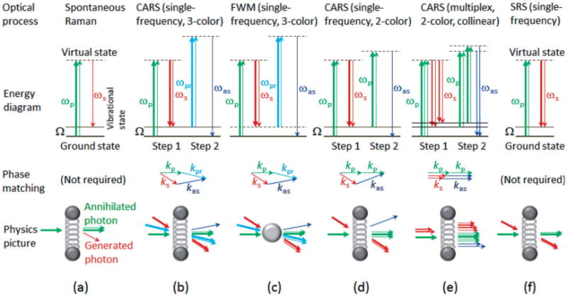
Other schemes have attempted to improve the standard scheme in terms of multiplex acquisition. Although a Raman spectrum can be retrieved by multiplexing single-frequency CARS (Scheme B, Scheme C [46]) or SRS [47] wherein a single detector is used, a slow electronic procedure in the spatial light modular is required for continuous phase cycling (Scheme C), or a specific device is required for continuous wavelength scanning (Scheme B, [46], [47]). In this sense, this strategy of multiplexing is not as simple as conventional multiplex CARS in which the CARS spectrum is acquired simultaneously from the array detector of a spectrometer [12, 13]. The original scheme of multiplex CARS employed a synchronized pair of ps-fs solid-state lasers [12, 13]. To lower the cost and broaden the spectral coverage, one appealing scheme employs a filtered spectral component of an fs laser as the pump/probe beam to define the CARS spectral resolution, and uses the fiber continuum generated from the same fs laser as the Stokes beam (Scheme D, Table 2). The non-resonant background can be removed by post-processing tools such as the Kramers-Kronig transform method and the maximum entropy method, producing passive interferometry-enhanced signal from cells [48] and tissues [49]. Alternatively, raw signal free of the non-resonant background can be obtained by delayed probing, provided that the fiber continuum is coherent and compressible (Scheme E, Table 2). Currently, these two schemes are limited by relatively low sensitivity (slow imaging speed) [15]. Improved sensitivity can be attained by increasing the excitation peak intensity (incident pulse energy) [50]. However, sample photo-damage and unwanted nonlinear effects may occur at high peak intensity excitation and should be carefully examined.
The standard scheme of CARS microscopy [10, 11] employs a pair of near-infrared solid-state picosecond (1–10 ps) laser oscillators, which produce two synchronized pulse trains for the pump/probe beam and the Stokes beam [Figure 2(a)]. The two pulsed beams are overlapped spatially and temporally by aligning them collinearly and adjusting the delay (τ) line of one of the two beams. The collinear beams are then sent to a microscope objective. Representative samples have included cells [10] and live mouse skin [11]. For thin samples, such as fixed cells or cells in culture, the forward propagating CARS signal is collected by another objective lens and recorded by a photomultiplier (PMT), while the backward (epi-) propagating CARS signal is collected by the focusing microscope objective and recorded by a second PMT. When imaging thick tissues, such as live mouse skin, only the backward signal can be recorded. Galvanometric mirrors are employed to raster scan the beams in the focal (x − y) plane of the microscope objective, so that a CARS image can be generated. Stage movement of the sample (or the microscope objective) along the z direction allows for depth-resolved three-dimensional imaging. The wavelength difference between the two beams is tunable, and can be used to stimulate, most typically, lipids (∼2900 cm−1) due to their strong signal, but also chromosomes (1090 cm−1). Video-rate imaging of lipids is possible [11].
Instructions: The base is constructed by attaching the plastic holder to a square piece of plywood and then adding four legs which extend outward. The big plastic tubing can be glued into the holder. At the top of the tubing, another plastic holder is put on, but not glued, so that the entire top of the mounting can be removed for adjustments and travel purposes. The top plastic holder is attached to a round piece of plywood which has a whole cut out of the middle and a screw inserted there. The support box will be attached here and can swivel 360 degrees. The support box is constructed much like a shoe box except that one side is missing. The bottom has a rectangle cut out of end (see where Travis's hand is). This allows the bracket assembly to rotate all the way to a position perpendicular to the ground. Also, on the end of the box opposite Travis, cut out a semicircle to allow the telescope to rotate all the way to a position parallel to the ground. The bracket assembly encases the telescope. It looks like this: It is made up of a rectangular three-sided box with end plates on either end (bottom). The end plates (at the top) have wing screws which allow the top half of the end plate to be removed from the tube bracket assembly, releasing the telescope. This is useful for making adjustments to the telescope itself or for using a different powered telescope in the same mounting. Notice also the round wooden pieces attached to either side of the support box in the above picture. Wood glue is applied around the circumference of the circle and the smaller plastic tubes, only about an inch in length, are squeezed on. These are the trunnions. The unique part of the mounting is the trunnion. Trunnion notch plates are attached to the insides of the left and right walls (when looking through the telescope) of the support box. Plastic Furniture tacks are stuck into the insides of the triangular cut-out and support the trunnions. These tacks can be moved at any time to increase or decrease friction so that the trunnions will move smoothly, but also not allow the tube bracket assembly (and thus the telescope) to slip. The tube bracket assembly, telescope, and support box combined can be removed from the base. The result is that our telescope moves freely through an entire hemisphere giving us the ability to look at anything in the sky. It was with this mounting that we were finally able to recreate some of Galileo's observations. If you would like more information on how to build a relatively cheap mounting for your Galilean telescope, just e-mail Tom Williams or Jessica Williams. Return to the astronomy group's home page .
(a) Multimodal microscopy of a 50 μm thick section of unstained rabbit aorta reveals endogenous lipids (CARS – red), collagen (second harmonic generation microscopy – blue), and smooth muscle elastin (two-photon fluorescence microscopy – green). The scale bar is 50 μm. Adapted from [23], with permission; (b) CARS hyperspectral images (500 × 500 μm2, color scale – blue to red) of a normal mammary tissue section (upper left) and a mammary tumor section (upper right), averaged CARS spectra of the two sections (lower left), and automated tumor margin identification (black curves) overlaid on a reconstructed CARS hyperspectral image of a third mammary tissue section (lower right). Adapted from [53], with permission.
In this review, we have identified six technical barriers that have largely limited the clinical translation of CARS microscopy. Although each barrier can be overcome by upgrading the standard CARS microscopy with a well-known advanced feature, none can be integrated without significant technical trade-off(s). Thus, the integration of different combinations of these features in various schemes of CARS microscopy has produced complementary strengths and weaknesses, and the optimal scheme for clinical translation remains unclear. By recognizing CARS spectroscopy vs. CARS imaging as the most fundamental tradeoff, we suggest that clinical CARS microscopy should be optimized to perform either Raman spectroscopy with a broad spectral coverage, or Raman imaging at one or a few discrete Raman frequencies, but not both. The former could be realized by integrating all of the six advanced features, resulting in a highly sensitive version of spontaneous Raman microscopy that could rapidly identify new Raman biomarkers of medical significance from thin ex vivo tissue sections. The latter would adaptively integrate some of the advanced features, depending on the identified Raman biomarkers and the technical issue of fiber-based miniaturization, to perform in vivo molecular imaging in patients.
This telescope mounting is composed of a base a support box for the telescope tubing and its bracket assembly a bracket assembly encasing the telescope tubing with trunnion bearings which fit into the trunnion notch plates attached to the inside of the support box Parts List: Polybutylene Pipe Diameter = 4", Length = approximately 5' These can vary. The length is approximately equal to the height that you desire. Polybutylene pipe for the trunnion (swivel) for the telescope tubing Diameter = 2", Length = approximately 2 pieces about 1" long This is glued to the tube bracket assembly with Wood glue Plastic furniture tacks These are used to stick into the bottom of the legs of chairs to protect the floor. They provide the foundation for the trunnions to turn. Wing Screws These are used for the end plates of the tube bracket assembly. They allow for the different telescopes to be used, just by unscrewing these and inserting a different telescope. Plastic floor flanges which can hold the big tubing and be nailed to the wood Nails, Bolts, Screws A whole lot of plywood! Suggested Tools: Power Saw circular saw Power Drill glue work bench to cut out various shapes of wood Instructions: The base is constructed by attaching the plastic holder to a square piece of plywood and then adding four legs which extend outward. The big plastic tubing can be glued into the holder. At the top of the tubing, another plastic holder is put on, but not glued, so that the entire top of the mounting can be removed for adjustments and travel purposes. The top plastic holder is attached to a round piece of plywood which has a whole cut out of the middle and a screw inserted there. The support box will be attached here and can swivel 360 degrees. The support box is constructed much like a shoe box except that one side is missing. The bottom has a rectangle cut out of end (see where Travis's hand is). This allows the bracket assembly to rotate all the way to a position perpendicular to the ground. Also, on the end of the box opposite Travis, cut out a semicircle to allow the telescope to rotate all the way to a position parallel to the ground. The bracket assembly encases the telescope. It looks like this: It is made up of a rectangular three-sided box with end plates on either end (bottom). The end plates (at the top) have wing screws which allow the top half of the end plate to be removed from the tube bracket assembly, releasing the telescope. This is useful for making adjustments to the telescope itself or for using a different powered telescope in the same mounting. Notice also the round wooden pieces attached to either side of the support box in the above picture. Wood glue is applied around the circumference of the circle and the smaller plastic tubes, only about an inch in length, are squeezed on. These are the trunnions. The unique part of the mounting is the trunnion. Trunnion notch plates are attached to the insides of the left and right walls (when looking through the telescope) of the support box. Plastic Furniture tacks are stuck into the insides of the triangular cut-out and support the trunnions. These tacks can be moved at any time to increase or decrease friction so that the trunnions will move smoothly, but also not allow the tube bracket assembly (and thus the telescope) to slip. The tube bracket assembly, telescope, and support box combined can be removed from the base. The result is that our telescope moves freely through an entire hemisphere giving us the ability to look at anything in the sky. It was with this mounting that we were finally able to recreate some of Galileo's observations. If you would like more information on how to build a relatively cheap mounting for your Galilean telescope, just e-mail Tom Williams or Jessica Williams. Return to the astronomy group's home page .
While a high-performance clinical spectroscopy scheme serves to conduct basic clinical research, the corresponding clinical imaging scheme should be optimized for a specific application of in vivo point-of-care diagnosis (Table 3). The development of the latter has been limited by a fundamental tradeoff between fiber-based implementation and excitation controllability (wavelength tunability, pulse dispersion and delay management, intensity modulation, etc.). On one hand, clinical imaging is expected to be performed by regular clinical staff with no extensive laser training (Table 3), so that the clinical imaging scheme should be built upon optical fibers and fiber-based components that eliminate daily optical alignment. On the other hand, the variation of the Raman frequency of interest requires tuning the wavelength(s) of incident pulses and managing their dispersion and/or delay, which are often challenging with fiber-based components. Because of this tradeoff, there is no optimal clinical imaging scheme universally applicable to different applications. To maximize the excitation controllability, one clinical imaging system selected all-free-space optical components, including a free-space arm for beam delivery [59]. At the opposite end of the spectrum, fiber optic components were predominantly used to avoid frequent optical alignment without compromising the wavelength tunability [46, 60]. Between these two extremes, several approaches adopted a hybrid format of free-space and fiber components to implement optical coherence tomography-like CARS microscopy [61], CARS endoscopy [62], and handheld CARS microscopy [63].
The base is constructed by attaching the plastic holder to a square piece of plywood and then adding four legs which extend outward. The big plastic tubing can be glued into the holder. At the top of the tubing, another plastic holder is put on, but not glued, so that the entire top of the mounting can be removed for adjustments and travel purposes. The top plastic holder is attached to a round piece of plywood which has a whole cut out of the middle and a screw inserted there. The support box will be attached here and can swivel 360 degrees. The support box is constructed much like a shoe box except that one side is missing. The bottom has a rectangle cut out of end (see where Travis's hand is). This allows the bracket assembly to rotate all the way to a position perpendicular to the ground. Also, on the end of the box opposite Travis, cut out a semicircle to allow the telescope to rotate all the way to a position parallel to the ground. The bracket assembly encases the telescope. It looks like this: It is made up of a rectangular three-sided box with end plates on either end (bottom). The end plates (at the top) have wing screws which allow the top half of the end plate to be removed from the tube bracket assembly, releasing the telescope. This is useful for making adjustments to the telescope itself or for using a different powered telescope in the same mounting. Notice also the round wooden pieces attached to either side of the support box in the above picture. Wood glue is applied around the circumference of the circle and the smaller plastic tubes, only about an inch in length, are squeezed on. These are the trunnions. The unique part of the mounting is the trunnion. Trunnion notch plates are attached to the insides of the left and right walls (when looking through the telescope) of the support box. Plastic Furniture tacks are stuck into the insides of the triangular cut-out and support the trunnions. These tacks can be moved at any time to increase or decrease friction so that the trunnions will move smoothly, but also not allow the tube bracket assembly (and thus the telescope) to slip. The tube bracket assembly, telescope, and support box combined can be removed from the base. The result is that our telescope moves freely through an entire hemisphere giving us the ability to look at anything in the sky. It was with this mounting that we were finally able to recreate some of Galileo's observations. If you would like more information on how to build a relatively cheap mounting for your Galilean telescope, just e-mail Tom Williams or Jessica Williams. Return to the astronomy group's home page .
This telescope mounting is composed of a base a support box for the telescope tubing and its bracket assembly a bracket assembly encasing the telescope tubing with trunnion bearings which fit into the trunnion notch plates attached to the inside of the support box Parts List: Polybutylene Pipe Diameter = 4", Length = approximately 5' These can vary. The length is approximately equal to the height that you desire. Polybutylene pipe for the trunnion (swivel) for the telescope tubing Diameter = 2", Length = approximately 2 pieces about 1" long This is glued to the tube bracket assembly with Wood glue Plastic furniture tacks These are used to stick into the bottom of the legs of chairs to protect the floor. They provide the foundation for the trunnions to turn. Wing Screws These are used for the end plates of the tube bracket assembly. They allow for the different telescopes to be used, just by unscrewing these and inserting a different telescope. Plastic floor flanges which can hold the big tubing and be nailed to the wood Nails, Bolts, Screws A whole lot of plywood! Suggested Tools: Power Saw circular saw Power Drill glue work bench to cut out various shapes of wood Instructions: The base is constructed by attaching the plastic holder to a square piece of plywood and then adding four legs which extend outward. The big plastic tubing can be glued into the holder. At the top of the tubing, another plastic holder is put on, but not glued, so that the entire top of the mounting can be removed for adjustments and travel purposes. The top plastic holder is attached to a round piece of plywood which has a whole cut out of the middle and a screw inserted there. The support box will be attached here and can swivel 360 degrees. The support box is constructed much like a shoe box except that one side is missing. The bottom has a rectangle cut out of end (see where Travis's hand is). This allows the bracket assembly to rotate all the way to a position perpendicular to the ground. Also, on the end of the box opposite Travis, cut out a semicircle to allow the telescope to rotate all the way to a position parallel to the ground. The bracket assembly encases the telescope. It looks like this: It is made up of a rectangular three-sided box with end plates on either end (bottom). The end plates (at the top) have wing screws which allow the top half of the end plate to be removed from the tube bracket assembly, releasing the telescope. This is useful for making adjustments to the telescope itself or for using a different powered telescope in the same mounting. Notice also the round wooden pieces attached to either side of the support box in the above picture. Wood glue is applied around the circumference of the circle and the smaller plastic tubes, only about an inch in length, are squeezed on. These are the trunnions. The unique part of the mounting is the trunnion. Trunnion notch plates are attached to the insides of the left and right walls (when looking through the telescope) of the support box. Plastic Furniture tacks are stuck into the insides of the triangular cut-out and support the trunnions. These tacks can be moved at any time to increase or decrease friction so that the trunnions will move smoothly, but also not allow the tube bracket assembly (and thus the telescope) to slip. The tube bracket assembly, telescope, and support box combined can be removed from the base. The result is that our telescope moves freely through an entire hemisphere giving us the ability to look at anything in the sky. It was with this mounting that we were finally able to recreate some of Galileo's observations. If you would like more information on how to build a relatively cheap mounting for your Galilean telescope, just e-mail Tom Williams or Jessica Williams. Return to the astronomy group's home page .
It should be noted that the envisioned clinical spectroscopy scheme with full integration [Figure 5(b)] may not be more sensitive than other spectroscopic schemes, particularly those employ high peak intensity excitation (Schemes F [50], etc.). Also, in contrast to multiplexed SRS, interferometric detection may not be applicable to multiply scattered signal photons, and may therefore hinder the application of the scheme to in vivo thick tissues or highly scattering tissue samples that require epi-imaging. Nevertheless, the fully integrated scheme [Figure 4(b)] possesses overall high performance, including good sensitivity, low cost/maintenance, friendly computer-controlled operation, and simple adaption to multimodal multi-photon imaging [Figure 3(a)].
Spectro-temporal property of the excitation pulse (a) in the envisioned clinical spectroscopy scheme with full integration (b). The 4f pulse shaper is a compact commercially available device with computer control (image from Bio-Photonics Solutions, Inc.).
The representative schemes of multiplex CARS have integrated different combinations of the advanced features, and therefore possess complementary strengths and weaknesses (Schemes D–G, Table 2). More advanced features under an increasing level of integration is beneficial because of their synergistic advantage, i.e., the whole is greater than the sum of its parts. The ideal scheme would integrate all six advanced features in a clinical spectroscopy scheme. This can be built upon Scheme G that has already integrated four advanced features, including the desirable feature of active interferometry (Table 2). One missing feature, however, is single-beam excitation, the characteristic feature of Scheme F, which overcomes the limitations of alignment drift and narrow Raman spectrum in Scheme G. Thus, the broadband continuum-like fs laser and the pixelated 4f pulse shaper of Scheme F are advantageous to be used as the optical source to replace the amplified laser chain of Scheme G (Table 2). With proper temporal pulse shaping [31] and spectral partitioning, the resulting single-beam scheme could be considered as if the two spectral gaps between the Stokes beam, pump/probe beam, and reference beam would almost disappear, so that the Stokes, pump, probe, and reference photons could be supplied by the broadband laser [Figure 5(a)]. Two spectral components are blocked to exclude the contamination of the 3-color CARS signal with the unwanted 2-color CARS signal from the pump/Stokes pulse and the probe pulse [Figure 5(a)].
Anti stokes raman spectroscopyformula
This image was produced by the star jumping in the field of view. We tried to have one person hold the telescope tube steady, but it takes very little movement to cause a star to move across the field of view when the field of view is only about 15 arc minutes. Moreover, our telescope would blow over often and required one person to hold it as still as possible, but this never really worked very well. So, we built a new mounting and stars looked like this, with very little distortion. The new mounting was constructed on a Saturday morning and afternoon, based on plans by Tom Williams. It looks like this: This telescope mounting is composed of a base a support box for the telescope tubing and its bracket assembly a bracket assembly encasing the telescope tubing with trunnion bearings which fit into the trunnion notch plates attached to the inside of the support box Parts List: Polybutylene Pipe Diameter = 4", Length = approximately 5' These can vary. The length is approximately equal to the height that you desire. Polybutylene pipe for the trunnion (swivel) for the telescope tubing Diameter = 2", Length = approximately 2 pieces about 1" long This is glued to the tube bracket assembly with Wood glue Plastic furniture tacks These are used to stick into the bottom of the legs of chairs to protect the floor. They provide the foundation for the trunnions to turn. Wing Screws These are used for the end plates of the tube bracket assembly. They allow for the different telescopes to be used, just by unscrewing these and inserting a different telescope. Plastic floor flanges which can hold the big tubing and be nailed to the wood Nails, Bolts, Screws A whole lot of plywood! Suggested Tools: Power Saw circular saw Power Drill glue work bench to cut out various shapes of wood Instructions: The base is constructed by attaching the plastic holder to a square piece of plywood and then adding four legs which extend outward. The big plastic tubing can be glued into the holder. At the top of the tubing, another plastic holder is put on, but not glued, so that the entire top of the mounting can be removed for adjustments and travel purposes. The top plastic holder is attached to a round piece of plywood which has a whole cut out of the middle and a screw inserted there. The support box will be attached here and can swivel 360 degrees. The support box is constructed much like a shoe box except that one side is missing. The bottom has a rectangle cut out of end (see where Travis's hand is). This allows the bracket assembly to rotate all the way to a position perpendicular to the ground. Also, on the end of the box opposite Travis, cut out a semicircle to allow the telescope to rotate all the way to a position parallel to the ground. The bracket assembly encases the telescope. It looks like this: It is made up of a rectangular three-sided box with end plates on either end (bottom). The end plates (at the top) have wing screws which allow the top half of the end plate to be removed from the tube bracket assembly, releasing the telescope. This is useful for making adjustments to the telescope itself or for using a different powered telescope in the same mounting. Notice also the round wooden pieces attached to either side of the support box in the above picture. Wood glue is applied around the circumference of the circle and the smaller plastic tubes, only about an inch in length, are squeezed on. These are the trunnions. The unique part of the mounting is the trunnion. Trunnion notch plates are attached to the insides of the left and right walls (when looking through the telescope) of the support box. Plastic Furniture tacks are stuck into the insides of the triangular cut-out and support the trunnions. These tacks can be moved at any time to increase or decrease friction so that the trunnions will move smoothly, but also not allow the tube bracket assembly (and thus the telescope) to slip. The tube bracket assembly, telescope, and support box combined can be removed from the base. The result is that our telescope moves freely through an entire hemisphere giving us the ability to look at anything in the sky. It was with this mounting that we were finally able to recreate some of Galileo's observations. If you would like more information on how to build a relatively cheap mounting for your Galilean telescope, just e-mail Tom Williams or Jessica Williams. Return to the astronomy group's home page .
"When there are no glasses in the tube, the rays proceed to the object FG along the straight lines ECF and EDG, but with the glasses put in they proceed along the refracted lines ECH and EDI. They are indeed squeezed together and where before, free, they were directed to the object FG, now they only grasp the part HI" Galileo, Sidereus Nuncius tr. Albert Van Helden, pp. 38-39. Actually, Galileo could not explain how his telescope magnified precisely. He did not understand, as we now know, that the magnification of his telescope can be computed by F/f (see top figure). Increasing the magnification requires lengthening the telescope. Our 10X telescope is about 4 feet long. From the above picture, you can see that an image, HI, will be viewed upright, making the Galilean telescope useful for terrestrial purposes as well as astronomical. Keplerian telescopes, in contrast, invert the image. What are the disadvantages of a Galilean telescope? The Galilean telescope's biggest disadvantage is its small field of view. A Galilean telescope typically has a field of view of about 15-18 arc minutes. The moon has a diameter of about 30 arc minutes, so the Galilean telescope only reveals approximately one-fourth of the moon's surface at one time. In the Houston skies, a typical field of view has only one star or no stars at all. This makes it very difficult to map a constellation. Increasing the magnification on the Galilean telescope, like all telescopes, reduces the field of view. Perhaps Galileo built a 30X telescope, but it is doubtful that he used much in his observations. The field of view must have been very tiny. How do you make a Galilean telescope?Building the Telescope Tube: Last Year's Group's Work Parts List (With approximate cost): Cardboard Telescoping Mailing Tube (1), $3 Diameter = 50mm (or 2"), Length = 1100mm (or 143") Should be comprised of an inner and outer tube with closed ends on the outer tube. Concave Convex Lens (the "objective lens") (1), $16 for this and the next lens as a pair. Focal Length = 1350mm (0.75 diopter) Cut to our specification of 49mm diameter. Plano Concave Lens (the "eyepiece") (1) Focal Length = -152mm (-6.6 diopter), Diameter = 49mm Cut to our specification of 49mm diameter. Suggested Tools: Coping Saw Alternatively, any other instrument that will make a relatively clean cut through the mailing tube. Drill (bit sizes discussed below) Super Glue Alternatively, any other kind of glue that will firmly hold the inner and outer mailing tubes together. It must be of a thin consistency. Greenlee Punch (optional) Instructions: The basic premise of the telescope tube is to align two lenses the appropriate distance from each other. For this telescope, the lenses are a concave convex (one side curved out and the other curved in) and a plano concave (one flat side and one side curved in). The plano concave lens is used as the "eyepiece" with the plano (flat) side facing the eye. The concave convex is used as the "objective lens" that is aligned with the eyepiece and with the convex side facing the sky. Notice that this lens is actually different than the plano convex lens used in the original Galilean telescope, but still gives the same results. The following design uses pieces of the inner tube of the mailing tube to hold the lenses in place inside the outer tube. This is best illustrated in the following diagram, which shows the cross section of the telescope tube: The outer tube of the mailing tube should have a short end that pulls off, and this can be used for the split in the outer tube shown above. This end will be used to hold the eyepiece. The inner tube must have two pieces (about 1" to 1.5" each) cut off of it that will be used as spacers to hold the objective lens in place. Make these cuts as straight and clean as possible, which will be difficult since the tube is made out of cardboard. A coping saw works pretty well for this. Take the short piece of the outer tube and cut or drill a hole (from 3/16" to 5/16" should be fine) directly in the center of the metal cap on the end. This will be the eyehole. It is important that this hole be as clean as possible (no metal protrusions) so that the the flat side of the eyepiece will fit snugly against the metal cap. An electrician's hole punch or Greenlee Punch works well for this task. If a drill is used, drill with a light pressure, then smooth out the inside surface as much as possible. Place the eyepiece flush (flat side) against the inside of this eyehole. The large piece of the inner mailing tube left will be used to hold this in place. To do this, drill small holes around the outside of the eyepiece tube. Then, with the eyepiece properly in place, slide the inner tube into it, put glue into the holes, and turn the tube a little bit to spread the glue inside. Hold the tube snugly against the lens inside the cap until the glue dries. Now, put this aside and take the large outer tube and the two spacers cut from the inner tube. Cut the closed end off of the outer tube, then use the other end to mount the objective lens (since that end already has a clean cut). Again, the "drill holes - put in glue" technique will be used to hold the spacers in place. First, check how far the inner spacer needs to be placed inside the tube so that the lens and other spacer will be able to sit inside the tube comfortably. Then drill holes in the outer tube around this area and glue in the spacer as before. After the first spacer is in place and dry, place the concave side of the objective lens flush against it, and put the other spacer snugly against the lens to hold it in place (again using the drill - glue method). Now there are two pieces, each containing one of the lenses. Slide the mailing tubes together as shown in the drawing above, and the telescope is done. By leaving these two pieces unglued, the telescope may be focused simply by sliding the eyepiece part inside the objective part. After a desired magnification/focus is found, the two pieces may be permanently attached (or some tape will give a semi-permanent attachment). Two images of a finished tube are shown below. The first picture shows the telescope tube from the objective side while the second image shows the ocular end of the tube: Making the Mounting: This Year's Work For the first half of the semester, we used the mountings built by last year's group. It looked like this: This image was produced by the star jumping in the field of view. We tried to have one person hold the telescope tube steady, but it takes very little movement to cause a star to move across the field of view when the field of view is only about 15 arc minutes. Moreover, our telescope would blow over often and required one person to hold it as still as possible, but this never really worked very well. So, we built a new mounting and stars looked like this, with very little distortion. The new mounting was constructed on a Saturday morning and afternoon, based on plans by Tom Williams. It looks like this: This telescope mounting is composed of a base a support box for the telescope tubing and its bracket assembly a bracket assembly encasing the telescope tubing with trunnion bearings which fit into the trunnion notch plates attached to the inside of the support box Parts List: Polybutylene Pipe Diameter = 4", Length = approximately 5' These can vary. The length is approximately equal to the height that you desire. Polybutylene pipe for the trunnion (swivel) for the telescope tubing Diameter = 2", Length = approximately 2 pieces about 1" long This is glued to the tube bracket assembly with Wood glue Plastic furniture tacks These are used to stick into the bottom of the legs of chairs to protect the floor. They provide the foundation for the trunnions to turn. Wing Screws These are used for the end plates of the tube bracket assembly. They allow for the different telescopes to be used, just by unscrewing these and inserting a different telescope. Plastic floor flanges which can hold the big tubing and be nailed to the wood Nails, Bolts, Screws A whole lot of plywood! Suggested Tools: Power Saw circular saw Power Drill glue work bench to cut out various shapes of wood Instructions: The base is constructed by attaching the plastic holder to a square piece of plywood and then adding four legs which extend outward. The big plastic tubing can be glued into the holder. At the top of the tubing, another plastic holder is put on, but not glued, so that the entire top of the mounting can be removed for adjustments and travel purposes. The top plastic holder is attached to a round piece of plywood which has a whole cut out of the middle and a screw inserted there. The support box will be attached here and can swivel 360 degrees. The support box is constructed much like a shoe box except that one side is missing. The bottom has a rectangle cut out of end (see where Travis's hand is). This allows the bracket assembly to rotate all the way to a position perpendicular to the ground. Also, on the end of the box opposite Travis, cut out a semicircle to allow the telescope to rotate all the way to a position parallel to the ground. The bracket assembly encases the telescope. It looks like this: It is made up of a rectangular three-sided box with end plates on either end (bottom). The end plates (at the top) have wing screws which allow the top half of the end plate to be removed from the tube bracket assembly, releasing the telescope. This is useful for making adjustments to the telescope itself or for using a different powered telescope in the same mounting. Notice also the round wooden pieces attached to either side of the support box in the above picture. Wood glue is applied around the circumference of the circle and the smaller plastic tubes, only about an inch in length, are squeezed on. These are the trunnions. The unique part of the mounting is the trunnion. Trunnion notch plates are attached to the insides of the left and right walls (when looking through the telescope) of the support box. Plastic Furniture tacks are stuck into the insides of the triangular cut-out and support the trunnions. These tacks can be moved at any time to increase or decrease friction so that the trunnions will move smoothly, but also not allow the tube bracket assembly (and thus the telescope) to slip. The tube bracket assembly, telescope, and support box combined can be removed from the base. The result is that our telescope moves freely through an entire hemisphere giving us the ability to look at anything in the sky. It was with this mounting that we were finally able to recreate some of Galileo's observations. If you would like more information on how to build a relatively cheap mounting for your Galilean telescope, just e-mail Tom Williams or Jessica Williams. Return to the astronomy group's home page .
There are other non-standard and “potentially advanced” features of CARS microscopy, such as polarization-based excitation/detection [36], wide-field imaging [37], and beam spatial shaping [38, 39]. Further studies are needed to demonstrate that these features can introduce more benefits than tradeoffs. The uniqueness of the six advanced features mentioned above is that they address the six limitations of the standard scheme relatively independent of each other. In other words, the presence of a subset of these features will not exclude the inclusion of the other features. Thus, there are in this view a total of 64 different schemes of CARS microscopy, each of which can be identified by the presence (or absence) of individual features (Table 2). The presence of a large number of schemes may have contributed to the large amount of scientific literature on this topic. Biological or heterogeneous material samples have provided challenging tests for demonstrating different schemes, and have been used to assess their applicability (Table 2).
It is made up of a rectangular three-sided box with end plates on either end (bottom). The end plates (at the top) have wing screws which allow the top half of the end plate to be removed from the tube bracket assembly, releasing the telescope. This is useful for making adjustments to the telescope itself or for using a different powered telescope in the same mounting. Notice also the round wooden pieces attached to either side of the support box in the above picture. Wood glue is applied around the circumference of the circle and the smaller plastic tubes, only about an inch in length, are squeezed on. These are the trunnions. The unique part of the mounting is the trunnion. Trunnion notch plates are attached to the insides of the left and right walls (when looking through the telescope) of the support box. Plastic Furniture tacks are stuck into the insides of the triangular cut-out and support the trunnions. These tacks can be moved at any time to increase or decrease friction so that the trunnions will move smoothly, but also not allow the tube bracket assembly (and thus the telescope) to slip. The tube bracket assembly, telescope, and support box combined can be removed from the base. The result is that our telescope moves freely through an entire hemisphere giving us the ability to look at anything in the sky. It was with this mounting that we were finally able to recreate some of Galileo's observations. If you would like more information on how to build a relatively cheap mounting for your Galilean telescope, just e-mail Tom Williams or Jessica Williams. Return to the astronomy group's home page .
How does a Galilean telescope work? The Galilean telescope was innovative in that he was the first to expand the range of magnification of the new spyglasses beyond 3X, using his particular set of lenses. In Sidereus Nuncius, Galileo described how these two lenses served to magnify an object. "When there are no glasses in the tube, the rays proceed to the object FG along the straight lines ECF and EDG, but with the glasses put in they proceed along the refracted lines ECH and EDI. They are indeed squeezed together and where before, free, they were directed to the object FG, now they only grasp the part HI" Galileo, Sidereus Nuncius tr. Albert Van Helden, pp. 38-39. Actually, Galileo could not explain how his telescope magnified precisely. He did not understand, as we now know, that the magnification of his telescope can be computed by F/f (see top figure). Increasing the magnification requires lengthening the telescope. Our 10X telescope is about 4 feet long. From the above picture, you can see that an image, HI, will be viewed upright, making the Galilean telescope useful for terrestrial purposes as well as astronomical. Keplerian telescopes, in contrast, invert the image. What are the disadvantages of a Galilean telescope? The Galilean telescope's biggest disadvantage is its small field of view. A Galilean telescope typically has a field of view of about 15-18 arc minutes. The moon has a diameter of about 30 arc minutes, so the Galilean telescope only reveals approximately one-fourth of the moon's surface at one time. In the Houston skies, a typical field of view has only one star or no stars at all. This makes it very difficult to map a constellation. Increasing the magnification on the Galilean telescope, like all telescopes, reduces the field of view. Perhaps Galileo built a 30X telescope, but it is doubtful that he used much in his observations. The field of view must have been very tiny. How do you make a Galilean telescope?Building the Telescope Tube: Last Year's Group's Work Parts List (With approximate cost): Cardboard Telescoping Mailing Tube (1), $3 Diameter = 50mm (or 2"), Length = 1100mm (or 143") Should be comprised of an inner and outer tube with closed ends on the outer tube. Concave Convex Lens (the "objective lens") (1), $16 for this and the next lens as a pair. Focal Length = 1350mm (0.75 diopter) Cut to our specification of 49mm diameter. Plano Concave Lens (the "eyepiece") (1) Focal Length = -152mm (-6.6 diopter), Diameter = 49mm Cut to our specification of 49mm diameter. Suggested Tools: Coping Saw Alternatively, any other instrument that will make a relatively clean cut through the mailing tube. Drill (bit sizes discussed below) Super Glue Alternatively, any other kind of glue that will firmly hold the inner and outer mailing tubes together. It must be of a thin consistency. Greenlee Punch (optional) Instructions: The basic premise of the telescope tube is to align two lenses the appropriate distance from each other. For this telescope, the lenses are a concave convex (one side curved out and the other curved in) and a plano concave (one flat side and one side curved in). The plano concave lens is used as the "eyepiece" with the plano (flat) side facing the eye. The concave convex is used as the "objective lens" that is aligned with the eyepiece and with the convex side facing the sky. Notice that this lens is actually different than the plano convex lens used in the original Galilean telescope, but still gives the same results. The following design uses pieces of the inner tube of the mailing tube to hold the lenses in place inside the outer tube. This is best illustrated in the following diagram, which shows the cross section of the telescope tube: The outer tube of the mailing tube should have a short end that pulls off, and this can be used for the split in the outer tube shown above. This end will be used to hold the eyepiece. The inner tube must have two pieces (about 1" to 1.5" each) cut off of it that will be used as spacers to hold the objective lens in place. Make these cuts as straight and clean as possible, which will be difficult since the tube is made out of cardboard. A coping saw works pretty well for this. Take the short piece of the outer tube and cut or drill a hole (from 3/16" to 5/16" should be fine) directly in the center of the metal cap on the end. This will be the eyehole. It is important that this hole be as clean as possible (no metal protrusions) so that the the flat side of the eyepiece will fit snugly against the metal cap. An electrician's hole punch or Greenlee Punch works well for this task. If a drill is used, drill with a light pressure, then smooth out the inside surface as much as possible. Place the eyepiece flush (flat side) against the inside of this eyehole. The large piece of the inner mailing tube left will be used to hold this in place. To do this, drill small holes around the outside of the eyepiece tube. Then, with the eyepiece properly in place, slide the inner tube into it, put glue into the holes, and turn the tube a little bit to spread the glue inside. Hold the tube snugly against the lens inside the cap until the glue dries. Now, put this aside and take the large outer tube and the two spacers cut from the inner tube. Cut the closed end off of the outer tube, then use the other end to mount the objective lens (since that end already has a clean cut). Again, the "drill holes - put in glue" technique will be used to hold the spacers in place. First, check how far the inner spacer needs to be placed inside the tube so that the lens and other spacer will be able to sit inside the tube comfortably. Then drill holes in the outer tube around this area and glue in the spacer as before. After the first spacer is in place and dry, place the concave side of the objective lens flush against it, and put the other spacer snugly against the lens to hold it in place (again using the drill - glue method). Now there are two pieces, each containing one of the lenses. Slide the mailing tubes together as shown in the drawing above, and the telescope is done. By leaving these two pieces unglued, the telescope may be focused simply by sliding the eyepiece part inside the objective part. After a desired magnification/focus is found, the two pieces may be permanently attached (or some tape will give a semi-permanent attachment). Two images of a finished tube are shown below. The first picture shows the telescope tube from the objective side while the second image shows the ocular end of the tube: Making the Mounting: This Year's Work For the first half of the semester, we used the mountings built by last year's group. It looked like this: This image was produced by the star jumping in the field of view. We tried to have one person hold the telescope tube steady, but it takes very little movement to cause a star to move across the field of view when the field of view is only about 15 arc minutes. Moreover, our telescope would blow over often and required one person to hold it as still as possible, but this never really worked very well. So, we built a new mounting and stars looked like this, with very little distortion. The new mounting was constructed on a Saturday morning and afternoon, based on plans by Tom Williams. It looks like this: This telescope mounting is composed of a base a support box for the telescope tubing and its bracket assembly a bracket assembly encasing the telescope tubing with trunnion bearings which fit into the trunnion notch plates attached to the inside of the support box Parts List: Polybutylene Pipe Diameter = 4", Length = approximately 5' These can vary. The length is approximately equal to the height that you desire. Polybutylene pipe for the trunnion (swivel) for the telescope tubing Diameter = 2", Length = approximately 2 pieces about 1" long This is glued to the tube bracket assembly with Wood glue Plastic furniture tacks These are used to stick into the bottom of the legs of chairs to protect the floor. They provide the foundation for the trunnions to turn. Wing Screws These are used for the end plates of the tube bracket assembly. They allow for the different telescopes to be used, just by unscrewing these and inserting a different telescope. Plastic floor flanges which can hold the big tubing and be nailed to the wood Nails, Bolts, Screws A whole lot of plywood! Suggested Tools: Power Saw circular saw Power Drill glue work bench to cut out various shapes of wood Instructions: The base is constructed by attaching the plastic holder to a square piece of plywood and then adding four legs which extend outward. The big plastic tubing can be glued into the holder. At the top of the tubing, another plastic holder is put on, but not glued, so that the entire top of the mounting can be removed for adjustments and travel purposes. The top plastic holder is attached to a round piece of plywood which has a whole cut out of the middle and a screw inserted there. The support box will be attached here and can swivel 360 degrees. The support box is constructed much like a shoe box except that one side is missing. The bottom has a rectangle cut out of end (see where Travis's hand is). This allows the bracket assembly to rotate all the way to a position perpendicular to the ground. Also, on the end of the box opposite Travis, cut out a semicircle to allow the telescope to rotate all the way to a position parallel to the ground. The bracket assembly encases the telescope. It looks like this: It is made up of a rectangular three-sided box with end plates on either end (bottom). The end plates (at the top) have wing screws which allow the top half of the end plate to be removed from the tube bracket assembly, releasing the telescope. This is useful for making adjustments to the telescope itself or for using a different powered telescope in the same mounting. Notice also the round wooden pieces attached to either side of the support box in the above picture. Wood glue is applied around the circumference of the circle and the smaller plastic tubes, only about an inch in length, are squeezed on. These are the trunnions. The unique part of the mounting is the trunnion. Trunnion notch plates are attached to the insides of the left and right walls (when looking through the telescope) of the support box. Plastic Furniture tacks are stuck into the insides of the triangular cut-out and support the trunnions. These tacks can be moved at any time to increase or decrease friction so that the trunnions will move smoothly, but also not allow the tube bracket assembly (and thus the telescope) to slip. The tube bracket assembly, telescope, and support box combined can be removed from the base. The result is that our telescope moves freely through an entire hemisphere giving us the ability to look at anything in the sky. It was with this mounting that we were finally able to recreate some of Galileo's observations. If you would like more information on how to build a relatively cheap mounting for your Galilean telescope, just e-mail Tom Williams or Jessica Williams. Return to the astronomy group's home page .
An alternative and complementary improvement of the standard scheme integrates the advanced features of single-beam excitation and nonlinear fiber wavelength conversion (Scheme A, Table 2), so that an all-fiber laser source suitable for clinical translation has been developed. The low repetition rate ps pulses from this source have peak intensity comparable to those of the fs lasers used in multi-photon microscopy, so that the third limitation of the standard scheme can also be circumvented. Thus, this scheme simultaneously overcomes the second, third, and fourth limitations of the standard scheme. However, this scheme retains the fifth and sixth limitations of the standard scheme, i.e., strong non-resonant background and inaccurate quantitative imaging, due to the nonlinear relation between the raw signal and Raman oscillators.


 Ms.Cici
 8618319014500