
Adjustable Mode Beam Technology - beam laser
Microscopeparts and functions
A lens is an optical device that can refract light. The refraction depends on the shape of a lens, which is typically convex or concave. For the purposes of microscopy, convex lenses are used for their ability to focus light at a single point. This is how the human eye works, with the convex biological lens focusing light on the back of your eye where rod and cone cells can detect it. Microscopes borrowed this idea, using convex lenses to focus light towards a point that is f distance away from the lens. This distance is known as the focal length of the lens and depends on the shape. Lens shapes can be seen in Fig.2. It should be noted that these lenses are symmetrical and will have the same effect on light from either direction.
Filters are optical components that can transmit certain wavelengths of light while reflecting others. Color selection is critical for fluorescence imaging. An example of optical filtering is shown in Fig.7.
In the fluorescence microscope, a combination of excitation BP filter, a LP dichroic filter and an emission BP filter are organized into a cube holder to provide high-intensity excitation light to the sample and efficiently isolate emission light before steering it off to the camera.
Very useful software and a very thank for making it available to use. Really needed this especially for University student
The aperture stop is the part of the imaging system that limits the range of angles of light the lens can collect from the sample. This range of angles defines the lens NA and therefore the system resolution, the ability to detect two objects as different. Most microscope objectives are designed such that the aperture stop is the Objective Rear Aperture, as seen in Fig.3A. This ensures that the objective defines the system resolution and that the resolution is the same across the entire field of view.
I would like to thank you about your website. It is very helpful for students and technical staffs. Also, graphical design is perfect. Have a nice day.
The construction is calculated using the mathematical apparatus of the finite element method. To obtain numerical values of diagrams and support reactions, you must Get an access code
this is amazing and has helped me so much. The only improvement i think that could be made would be the inclusion of beam profiles.
Putting the illumination source close to the sample limits control of light intensity and illumination field of view. Köhler imaged the light source to a focal length from the condenser lens, as illustrated in Fig.5. This provides control of the field of illumination, with a field stop in the middle of the imaging component and an aperture stop 1f away from the condenser. The aperture stop is a highly significant aspect of the design; allowing easy control of the light power to the sample. These stops usually have levers allowing the user to manually adjust the illumination area (field stop) and power (aperture stop) being delivered to the sample.
There are all kinds of cameras that can be used with a microscope. Key experimental considerations are the sensitivity, resolution, field of view and speed of a camera. For a detailed explanation, see our articles on these subjects.
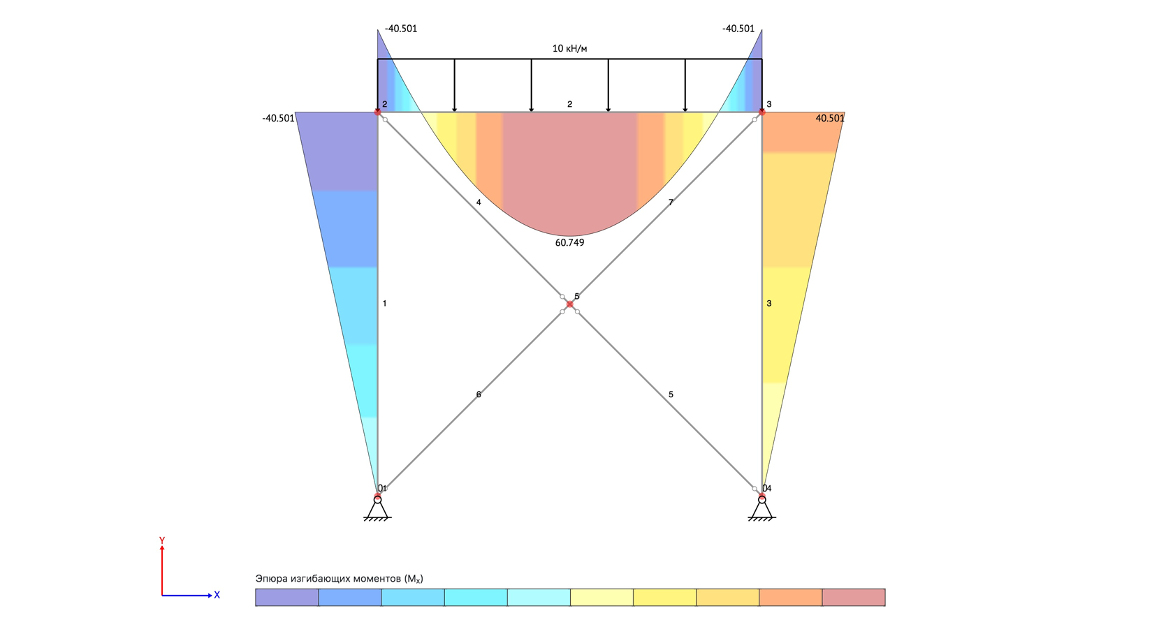
Figure 6: Normalized intensity versus wavelength plot of LEDs useful for fluorescence microscopy. Taken from http://www.fluorescencemicroscopy.it/en/illumination.html
This is the best website for calculating the numericals related to beam. I really want to thank the developers for making this. I am definitely gonna share it with my friends in my college.
The output of most microscopes is an image about 2 cm across, so this is typically magnified again in order to fill the field of view of the eyes. Eyepieces, another magnification system, give between 10x to 30x magnification on top of that provided by the objective and microscope. In combination with the lens in the eye, this magnifies the image to the retina at a useful scale, so that the human eye may resolve and observe objects even as small as cells (~10 µm).
I don't know how to thank and appreciate you for this website and I wish you build more Engineering sections like this. I am really happy with this website. wish you all the best
Various microscopy methods detect specific interactions between light and the sample. Methods that image scattered or absorbed light focus illumination light to the sample using a separate illumination lens and imaging objective. The focusing illumination lens is referred to as a condenser, with its own properties of working distance, NA, etc.
5. Spring, K.R., Parry-Hill, M. & Davidson, M.W. Geometrical Construction of Ray Diagrams in the Olympus Microscopy Primer website (https://www.olympus-lifescience.com/en/microscope-resource/primer/java/components/characteristicrays/)
Bigger pixels have benefits to sensitivity. Indirectly, they also have benefits on the total time it takes to get the information out to the computer. Total readout time is dependent on camera architecture, with CMOS being faster than CCD, but also on the total number of pixels in the camera. In general, a camera with bigger but fewer pixels will be ready for the next exposure faster that a camera with more, smaller pixels.
Whatiseyepieceinmicroscope
A camera pixel is the individual light-measuring unit in the camera, and the camera's sensor has arrays of pixels to measure the light across the field of view. A camera might have as few as 128×128 pixels, or as many 5000×3000 (15 million pixels, or 15 megapixels) or more. Since microscope camera ports commonly have the same approximate size, cameras with larger pixel arrays usually have smaller individual pixels.
High power objectivemicroscopefunction
Microscope objectives contain lenses but are not as simple as the lenses seen in Fig.2, making them complex lenses (Fig.3A). While the overall effect can be magnification, these lenses are carefully designed to control a variety of aspects of lenses, such as working distance, and the ability to correct problems such as aberrations. Objectives are characterized by two factors: magnification and numerical aperture (NA). Objective magnification ranges from 2x to 100x (and is combined with the eyepiece magnification), magnifying the sample 2-fold to 100-fold respectively (Fig.3B). NA is related to the focal length of the lens, namely what angle light exits/enters the objective, as this affects the resolution (Fig.3C, read our app note on resolution and NA for more). See Fig.3 for more information.
Thanks for providing such a comprehensive tool. I'm very pleased that I found your Beam Calculator because none of the other websites I visited had anything like the detail in the "solve" area.
Figure 5: Köhler illumination optics. The lamp has a zig-zag filament on the left-hand housing, and the sample is to the right. Working from left to right, light from the lamp is imaged to a position 1F from the principal plane of the condenser. Light with structure entering the condenser is scrambled upon delivery to the sample. The field stop provides control of the area in the sample that is illuminated. The aperture stop controls the range of angles, and the power, of the illumination. The light path from a central point of the filament at left to the sample at right is highlighted in orange. Derived from Biomedical Engineering Dept at Boston University.
Figure 8: Transmittance versus wavelength for various filter types. In the LP example, red light would pass through and blue light would be reflected. In the SP example, blue light would pass and red light reflected. In the BP example, both blue and red light is reflected while green light is transmitted. Taken from Basic Aspects of Light Filters Molecular Expressions Optical Microscopy Primer https://micro.magnet.fsu.edu/primer/lightandcolor/filtersintro.html
I love your site, very simple and easy to use I mostly use it to check my own diagrams maybe add a third decimal place otherwise its perfect!
Armmicroscopefunction
Pixel size is key to being able to image with the full information content provided by the optics. Camera pixels are square and usually 3-24 µm along the edge. Generally speaking, cameras with smaller pixels allow for higher resolution imaging whereas cameras with larger pixels have a larger surface area for photon collection making them more sensitive.
Stagemicroscopefunction
Thank you so much. I love this calculator SO MUCH. Every time I need to confirm if my results are good or not when making beams this is what i have as my first option. This is the best one!
This website is amazing. Easy to use, well elaborated answers. Better than SkyCiv which requires a premium account for everything!
These components are responsible for the magnification, resolution, and field of view inherent in the microscope. In this article, the details of microscope components and anatomy are explained in relation to how they contribute to providing the best possible image. In order to see the arrangement of these components, see Fig.1.
Köhler invented a focusable illumination system that allowed control of the field size, the power and the angle of illumination while scrambling the structure of the light source projected on the sample. He took advantage of the property of a lens to convert the lateral structure into parallel rays to do this. Putting an illumination source at the focal point of the lens transforms the output into uniform light rays on the other side, scrambling any structure inherent in the source. Multiple points emitting from the light source all end up scrambled and traveling in parallel rays after exiting the lens
Lasers provide light with highly specific wavelengths. For example, the light generated by a helium-neon (HeNe) laser has a color of 632.8 nm. Unlike the other light sources discussed here, lasers provide coherent light. Coherence indicates that the light is highly structured, with all the peaks and troughs of the light wave occurring at the same time and place. Coherence is necessary when focusing light to a diffraction-limited point, but also complicates widefield illumination due to its tendency for positive and negative interference. This self-interference can often be detected as a speckle pattern in an expanded laser beam.
The useful life of each of these sources varies between a few hundred hours for mercury arc lamps, to 1000-2000 hours for mercury/metal halide and halogen lamps.
Figure 1: Cut-away image of a modern microscope. There are two independent illumination pathways; 1) Epi-illumination reflected through the objective lens to illuminate the sample from above, 2) Trans-illumination focused by a separate condenser lens to illuminate the sample along the imaging axis of the microscope. There is a single imaging pathway for light, from the sample, through the objective and tube lenses and into the detector/camera or eyepiece. Derived from an image of a microscope on the Olympus Microscopy Primer and modified by the author.
To get the numerical values of the diagrams and the detailed text of the calculation, you need toGet a Detailed Report (detailed report example) Get a Detailed Report
Excellent service for students such as me. Look forward to further use of this service. I would appreciate more in formation regarding other calculators that you have available. Thank you.
Good night. Mundo name is andre and I’m studying mechanical engineering. I wanted to tell you that this calculator has been REALLY useful, I can compare the problems I solve and check if they they’re right now. You should make an app!
The beam calculator allows you to calculate the internal forces in statically indeterminate beams and frames using the finite element method. Result analysis of the structure by finite element method does not contain a detailed report on the progress of finding internal forces.
This website is great; the best one that I have found so far to draw shear force and bending moment diagrams. Three ways in which it could be improved: 1) Allow a distributed load to be inputted as an equation i.e. more complex distributed load. 2) Calculate the shear force and bending moment diagrams for frames as well. 3) Allow hinges to be added to the beam as well. Thanks for the great website.
Condensermicroscopefunction
Two illumination methods, critical or Köhler, are commonly used to illuminate the sample in microscopy. The primary difference is whether they copy the structure (critical) or scramble the structure (Köhler) of the illumination source at the sample. As Köhler illumination is more frequently used, it will be covered in this article.
There are a variety of lamps, light-emitting diodes (LEDs) and lasers that can be used to illuminate the sample in the microscope. Typical lamps used for illumination include:
Filters are commonly referred by the nature of their transmission, and the wavelength where they switch from transmission to reflection, as illustrated in Fig.8. A 500 nm short pass (SP) filter would transmit light bluer than 500 nm and reflect light redder than 500 nm. In contrast, a 500 nm long-pass (LP) filter will transmit light longer than 500 nm, reflecting light of shorter wavelengths.
Been struggling all day trying to find an example about this topic online, but did find anything the help, until I've decided to look for a calculator instead then found this very convenient and useful website. Helped a lot
Amazing website, very helpful for verifying homework solutions. Also appreciate that this is a free tool. Similar websites ask for payment to see as detailed results. Thanks!
2. Davidson, M.W. Koehler Illumination in the Zeiss Basic Resources website (https://w ww.zeiss.com/microscopy/us/solutions/reference/basic-microscopy/koehler-illumination.html)
The tool is fully functional, so visit our Beam Calculator and Frame and Truss Calculator to get started! It will work for all beams, trusses and frames and is capable of taking point loads, concentrated moments and distributed loads. It is also extremely adjustable and customizable to allow you to generate your own beam, frame or truss using templates of constructions. It is an extremely accurate tool, and unlike current calculators, very user-friendly. It is an extremely useful tool for university, college and high school students who tediously have to redraw BMDs and SFDs for assignments and practice/tutorial questions.
By combining the properties of SP and LP filters, bandpass (BP) filters were created. A SP 550 nm filter combined with a LP 500 nm filter would transmit light only between 500-550 nm. BP filters are usually described by their center wavelength and the allowed wavelengths to either side. A hypothetical SP550, LP500 filter combination is commonly referred to as BP 525d25, a BP centered at 525 nm with 25 nm transmission permitted to either side (Reichman, 2017).
Body tubemicroscopefunction

To get the numerical values of the diagrams and the detailed text of the calculation, you need to Get an Access Code (detailed report example)
3. Parry-Hill, M.J., Vogt, K.M, Griffin J.D., and Davidson, M.W. Matching Camera to Microscope Resolution in the MicroscopyU website (https://www.microscopyu.com/tutorials/matching-camera-to-microscope-resolution)
The focal length of a microscope objective lens needs to be very small, as the objective is often very close to the sample. Typically, the higher the magnification, the closer the objective needs to be.
The parts of the microscope discussed here work in concert to send light to the sample and take the light from the sample and magnify it up to the detector for collection. Aperture stops, usually in the objective, limit the microscope resolution. Field stops limit the area illuminated or detected. Components such as objectives, light sources, filters, and cameras all must be considered to get the best possible image.
Fluorescence microscopy uses reflection or epi-fluorescence geometry, where the objective serves as both the illumination condenser and the imaging lens. The illumination light is passed through the objective and the detected light is passed backward through the objective and split off to a camera or eyepiece. One benefit of this approach is that light that doesn't interact with the sample travels away from the detector, maximizing separation of illumination light from fluorescent emission. The transmission and epi-fluorescence light paths are illustrated in Figure 4.
The construction is calculated using the mathematical apparatus of the finite element method. The bending stiffness of the beam in all sections is accepted the same. To obtain numerical values of diagrams and support reactions, it is necessary to Get numerical values Get Numerical Values
The section designer allows you to design custom composite sections from both rolled profiles (I-beam, channel, Taurus, square pipe, etc.). The platform allows you to generate a detailed report on geometric characteristics such as: cross-sectional area, coordinates of the center of gravity, static moments, moments of inertia and moments of resistance.
Loving BeamGuru. If I had written this App it would look just like this. Congratulations... I will be showing this to all our first years.
Figure 4: Transmission/trans-fluorescence and reflection/epi-fluorescence microscopy light paths in a model microscope. The gray area indicates the light paths involved for each mode. Derived from an image of a microscope on the Olympus Microscopy Primer and modified by the author.

These are excellent visual representations. You guys should add an option to turn on/off the numbers leaving the beam, supports and variables.
BEAMGURU.COM is a online calculator that generates Bending Moment Diagrams (BMD) and Shear Force Diagrams (SFD), Axial Force Diagrams (AFD) for any statically determinate (most simply supported and cantilever beams) and statically indeterminate beams, frames and trusses. The calculator is fully customisable to suit most beams, frames and trusses; which is a feature unavailable on most other calculators.
I've been using this site for long, and I'll admit that this is the best beam calculator online out there in the market.
There are always constraints to the area to be imaged and the detailed information a microscope provides. There are physical blocks in the light path, typically named stops, diaphragms, or apertures. Here, the term stop will be used. For the imaging path, they may or may not be adjustable by the user, but as discussed later, the same concepts apply to the illumination optics.
4. Reichman, J. 2017 Handbook of Optical Filters for Fluorescence Microscopy. Chroma Technology Company Bellows Falls, Vermont 05101-3119 (https://www.chroma.com/sites/default/files/HandbookofOpticalFilters.pdf)
LED light sources are powerful enough to compete with xenon and mercury/metal halide lamps as illumination sources for fluorescence imaging. Each LED has a unique color, so LED broad band sources are derived from arrays of multiple individual diodes of relatively narrow spectra. LED sources have lifetimes of 10,000+ hours of use and are highly energy-efficient, making them very economical over long term use. They can be turned on and off quickly, over nanoseconds, making them useful for experiments requiring tight control of illumination. The spectral distribution of an example LED light source is illustrated in Fig.6.
6. Spring, K.R., Parry-Hill, M., Burdett, C.A., Sutton, R. T., Fellers, T.J. and Davidson, M.W. Laser Fundamentals in the Olympus Microscopy Primer website (https://www.olympus-lifescience.com/en/microscope-resource/primer/lightandcolor/laserhome/)
I learned these software in my diploma college Agnel Polytechnic by Hand Sir. These app help a lot to do my works. A very big thanks to the maker of these app.
Very useful tool. Even for someone who has been doing moment diagrams for years, sometimes there's still uncertainty. Definitely a great way to check ones work.
Figure 2: Convex vs concave lenses. A convex lens is thicker at the center than the edge and will focus a beam of light to a point a certain distance in front of the lens (the focal length). A concave lens is the opposite, being thicker at the edge than the center and spreading out a beam of light. Microscopes use convex lenses in order to focus light. Image from http://clubsciencekrl.blogspot.com/.
The platform allows you to automatically carry out the calculation of statically determinate beams to form a detailed report. To automatically select the beam section of the strength criteria (check for normal and shear stresses, for the third theory of strength) for statically determinate and statically indeterminate beams.
I love that website very much and the best thing here is that the site is free. I hope to find it as an app in Android Devices.
This website is great! I was having trouble understanding some simple beam problems when being asked to draw the shear force/bending moment diagrams. Using this tool I was able to understand where I was messing up and how to correct my mistake so that I could correctly solve for my reaction forces and draw my shear force diagram. It was also quite helpful for checking my work!
To the who created this website, I just discovered this website. I would like to say and convey a million thanksssss to team who created this website. It is very useful for engineering student. My dream is to become a lecturer in the Structural Engineering field. When i become one, I will definitely recommend to my students this website. Thank you so much for creating this ingenious website.
At its core, a typical microscope is essentially a box designed to hold two lenses in precise positions so that light can be accurately magnified from the sample to the detector. The first of these two lenses is the objective lens, which is located close to the sample, moves when the focus dial is turned and has useful information such as magnification written on its side. The second is commonly referred to as the tube/collector lens, which is buried deep within the body of the microscope and rarely seen.
Love the beam calculator. I'm a ME student and have learned more about the basics of generating bending and shear diagrams from your calculator than I have in my deforms class. Kudos and many thanks!
Nosepiecemicroscopefunction
It's very helpful. Even for industrial or educational purpose. Thank you for creating this. Please create more useful tools. Good luck!
Man this is one amazing tool. Great work. Saved my time like anything. Really needs time and patience to design such a tool. Extremely useful for study and research purpose. Hats off!!
Figure 3: On microscope objective lenses. A) An example of the location of lenses in an objective cross-section, making this a complex lens. B) Different Nikon Super Fluor objectives, ranging from 10x to 40x. The red boxes show the magnification / NA of the lens, with the air 40x having an NA of 0.90 and the oil-immersion 40x having an NA of 1.30, showing the effect of the imaging medium on the NA (the denser the better). C) How different NA affects the illumination of the sample, the higher the NA the greater the angle of light from the objective, and the greater the maximum resolution.
The field stop limits the area that can be imaged. This can't be bigger than the diameter of the tube lens. At best, the area imaged is the diameter of this lens divided by the magnification. If the internal lens has a diameter of 25 mm and the magnification is 100x, one should see a circle with a diameter of 250 µm of the sample. Things suc h as light modifying elements, or the detector itself, can easily reduce the field of view that is collected.
Figure 7: Modern color-selecting interference filter. The various layers on top of the glass substrate acting in total reflect blue light while allowing transmission of the red light. Taken from http://zeiss-campus.magnet.fsu.edu/articles/lightsources/leds.html
This website is awesome and really helped me with the question that I was stuck on. I will for sure come back to this website in the future.
I love this site. Thank you for free beam calculator. Its really helping. You're rock guys. Maybe it would be much better if you add hinge.
Hi, I'm a civil engineering student from Brazil and I want to thank all of you guys who made this incredible website!! It helped me a lot! Thanks
Most microscopes have optical exit ports with a diameter of around 18-25 mm. Using no magnification (1x objective), the image would, therefore, cover 18-25 mm of the sample. Given the fixed size of the image, camera sensors with diagonal dimensions greater than the microscope camera port would have pixels with no light falling on them. Therefore, it is important to match the field of view of the camera with the maximum field of view of the microscope.


 Ms.Cici
 8618319014500