
Adhesive Neodymium Magnets - Value Pack 60pcs D.10mm - 10mm magnets
The CON8ML-4 connector can be used to mate mounted LEDs featured on this page to user-supplied power supplies. We also offer a male 4-Pin M8 connector cable (item # CAB-LEDD1).
Optical Bandpass filter: Transmits a specific range of wavelengths, while blocking other wavelengths. ... Dichroic beamsplitter: Splits a beam of light into two ...
For each LED, a DC2200 High-Power LED Driver was used to drive the LED over a range of preset current values. At each current value, the OSA took five scans across the LED spectrum and combined them to create an average spectrum. The OSA identified the peak wavelength by finding the highest intensity value within 50 nm of the predicted peak wavelength and then calculated a centroid wavelength as described above. Centroid wavelengths were identified every 0.05 A up to the current limit of the LED. The entire process was repeated four times for each LED. All measurements were taken with the OSA in the absolute power and high-resolution spectrometer modes (for more information on the OSA operating modes, see the full web presentation).
Patch Cable OptionsThese LEDs are compatible with many of our multimode fiber patch cables; see below for a list of recommended fiber patch cables for different wavelength LEDs. In addition to SMA-terminated patch cables, we also offer hybrid patch cables with an SMA connector on one end and an FC/PC connector, ferrule end, or bare fiber on the other end. Cable configurations not available from stock can be requested through our custom patch cable tool.
Collimated Microscopy LEDs; Mounted LEDs · Cage-Compatible Diffuse Backlight LED · Illumination Kits · 4-Wavelength High-Power LED Source · Chrolis™ 6- ...
To fully support the maximum optical power of the LED you intend to drive, ensure that the max voltage and max current of the driver are equal to or greater than those of the LED.
The results of these measurements are provided in the table below and can be viewed by clicking on the graph icons. For each LED, the centroid wavelengths over all of the runs were averaged for each current point and plotted. To give a sense of possible variation in performance, the minimum and maximum wavelengths measured at each current point over all of the experimental runs are indicated by red error bars. At the lowest current values, the LED intensity was too weak to rise above the level of the noise and provide a reasonably accurate measurement of the wavelength. In these cases, we have omitted the affected currents from the graphs.
White Light and Broadband LEDOur cold white and warm white LEDs feature broad spectra that span several hundred nanometers. The difference in perceived color between these two LEDs can be described using the correlated color temperature, which indicates that the LED's color appearance is similar to a black body radiator at that temperature. In general, warm white LEDs offer a spectrum similar to a tungsten source, while cold white LEDs have a stronger blue component to the spectrum. Cold white LEDs are more suited for fluorescence microscopy applications or cameras with white balancing, because of a higher intensity at most wavelengths compared to warm white LEDs.
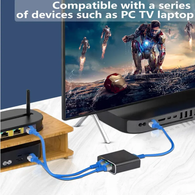
Answer 2: Yes, this network switch can support multiple devices simultaneously, making it ideal for home or small office use.
The thermal dissipation performance of these fiber-coupled LEDs has been optimized for stable power output. The heat sink is directly mounted to the LED mount so as to provide optimal thermal contact. By doing so, the degradation of optical output power that can be attributed to increased LED junction temperature is minimized.
Fiber opticlighting for homes
Driver OptionsThorlabs offers six drivers compatible with some or all of these LEDs: LEDD1B, UPLED, DC40, DC2200, DC4100, and DC4104 (the latter two require the DC4100-HUB). See the LED Drivers tab for a list of specifications, and the Specs tab for driver compatibility information. The UPLED, DC40, DC2200, DC4100, and DC4104 drivers are capable of reading the current limit from the EEPROM chip of the connected LED and automatically adjusting the maximum current setting to protect the LED.
Fiber OpticLight strands
The new portal, Hoya360, will integrate all current sources of club and academic information for Georgetown students in one location. A version of the portal ...
Answer 4: Yes, this network switch is designed to be user-friendly. It doesn't require any complex configuration or software installation.
Answer 5: This network switch can extend your network by up to 100 meters, making it suitable for most home and small office needs.
Optic fiber ledfor sale
Optimized Thermal ManagementThese fiber-coupled LEDs possess good thermal stability properties. The 34 mm long, passively cooled heat sink used in most of our fiber-coupled LEDs is in direct contact with the metal-core circuit board on which the LED is mounted. This minimizes the degradation of optical output power caused by increased LED junction temperature. Some of our fiber-coupled LEDs with a higher power output (M365FP1, M385FP1, M395FP1, M405FP1, and M660FP1) are mounted to a 50 mm long heat sink for increased heat dissipation and thermal stability.
Fiber opticlamp Vintage
One characteristic of LEDs is that they naturally exhibit power degradation with time. Often this power degradation is slow, but there are also instances where large, rapid drops in power, or even complete LED failure, occur. LED lifetimes are defined as the time it takes a specified percentage of a type of LED to fall below some power level. The parameters for the lifetime measurement can be written using the notation BXX/LYY, where XX is the percentage of that type of LED that will provide less than YY percent of the specified output power after the lifetime has elapsed. Thorlabs defines the lifetime of our LEDs as B50/L50, meaning that 50% of the LEDs with a given Item # will fall below 50% of the initial optical power at the end of the specified lifetime. For example, if a batch of 100 LEDs is rated for 150 mW of output power, 50 of these LEDs can be expected to produce an output power of ≤75 mW after the specified LED lifetime has elapsed.
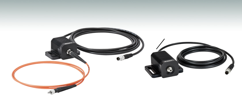
These fiber-coupled LEDs each consist of an LED mounted to a heat sink with an SMA fiber bulkhead. They can be easily integrated into an optical setup using one of our SMA-terminated multimode fiber patch cables. When the patch cable is connected to the SMA bulkhead on the LED housing, the LED will be butt-coupled to the SMA fiber connector. Hybrid patch cables can be used to transition from an SMA connector to an FC/PC connector, ferrule end, or bare fiber. For compatible drivers to power these LEDs, please see the LED Drivers tab. Please note that the minimum output powers specified below apply when the LED is used with a Ø400 µm core multimode fiber patch cable.
Jun 27, 2023 — The coating reduces reflections on the lens to reduce distractions and allow you to see more of what's ahead of you. It also increases your eye ...
Fibreopticcable
When straight lines are curved inwards in the shape of a barrel is called barrel distortion. Please see the illustrations below for barrel ...
The MBB1F1 fiber-coupled LED has been designed to have relatively flat spectral emission over a wide wavelength range. Its FWHM bandwidth ranges from 500 nm to 780 nm, while the 10 dB bandwidth ranges between 470 nm and 850 nm. For more information on the spectrum of this broadband source, please see the table to the right.
A lamp (i.e., bulb) sits on a movable track behind a Fresnel lens and in front of a spherical reflector. The reflector directs most of the light towards the ...
The Silver Needle, Fine Needlework Materials, everything for cross stitch. 6068 S. Sheridan Rd. Tulsa, Ok. 74145 (918) 493-1136 (888) 543-7004 E-Mail.
Please note that the connectors on these fiber-coupled LEDs are intended for SMA connectors only. To prevent mechanical damage to the LED, the ferrule length of the attached connector must not exceed the maximum length for SMA connectors of 9.812 mm as defined by the EN61754-22:2005 standard.
This tab includes all LEDs sold by Thorlabs. Click on More [+] to view all available wavelengths for each type of LED pictured below.
Microscope Notes · The eyepiece, also called the ocular lens, is a low power lens. · The objective lenses of compound microscopes are parfocal. · The field of view ...
Bestoptic fiber led
LEDs have relatively broad, asymmetric emission profiles. The centroid wavelength of an LED is a weighted average of the wavelength across the emission profile (following a similar concept to center of mass calculations). It is defined as
For applications where a hybrid patch cable is not practical, we can configure these fiber-coupled LEDs with FC/PC bulkheads; contact Tech Support for details.
Answer 3: Yes, this network switch comes with two network cable splitters, allowing you to extend the reach of your existing network to other areas of your home or office.
The spectrum of each LED and associated data file can be viewed by clicking on the links in the table to the right. Multiple windows can be opened simultaneously in order to compare LEDs.
where I(λ) is the intensity at each wavelength, λ. As a result, we chose to follow each LED's centroid wavelength as the current was varied in order to capture effects of both the peak wavelength shift and any changes to the overall spectral profile. The OSA's Peak Track mode will automatically calculate the centroid wavelength of a spectral peak, using a user-set lower intensity limit to determine the upper and lower limits (λ2 and λ1) of the wavelength range included in the calculation. In our case, we set the lower limit to 6 dB below the peak intensity.
Pin ConnectionThe diagram to the right shows the male connector of the fiber-coupled LED assembly. It is a standard M8 x 1 sensor circular connector. Pins 1 and 2 are the connection to the LED. Pins 3 and 4 are used for the internal EEPROM (electrically erasable programmable read-only memory) in these LEDs. If using an LED driver that was not purchased from Thorlabs, be careful that the appropriate connections are made to Pin 1 and Pin 2 and that you do not attempt to drive the LED through the EEPROM pins.
All LEDs will show some variation in their spectral profile and peak wavelength as a function of the drive current. For our fiber-coupled LEDs, we used an Optical Spectrum Analyzer (OSA) to track this wavelength shift as the current of the LED was increased from near zero to the maximum current.
Fiber OpticLights for Ceiling
Optical lens elements · Optical filters · Collimators · Prisms · Lasers.
Each fiber-coupled LED consists of a single LED that is coupled to the optical fiber using the butt-coupling technique. During this process, the fiber connector is positioned so that the end of the fiber will be as close as possible to the emitter, thereby minimizing losses at the fiber input and maximizing output power. The coupling efficiency is primarily dependent on the core diameter and the numerical aperture (NA) of the connected fiber. Larger core diameters and higher NA values give rise to reduced losses and increased output power at the end of the fiber. Additionally, high-OH content or solarization-resistant fibers are recommended for use with LED wavelengths below 400 nm (please refer to the table below for recommended patch cables).
Wasatch Photonics VPH transmission gratings delivery high efficiency. Our volume phase holographic gratings provide high performance over broad bandwidths.
Optogenetics ApplicationsOur fiber-coupled LEDs are ideal light sources for optogenetics applications. They feature a variety of wavelength choices and a convenient interconnection to optogenetics patch cables. Additionally, up to four different light sources can be driven and modulated simultaneously with our DC4100 controller and DC4100-HUB hub. Click here for our entire line of optogenetics products.


 Ms.Cici
 8618319014500