
ACCObeam - Acoustic collimated beam - collimated beam
It is meant to educate adult and pediatric endocrinologists, clinical geneticists, genetic counselors, reproductive endocrinologists, neonatologists, urologists ...
Optical tablesfor sale
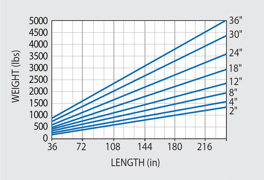
Figure 48.1. Approximate weights of 4' wide tables with 3/16" thick top and bottom skins. Weights of 3' and 5' wide tables are in direct proportion to width. Image Credit: Kinetic Systems, Inc
Figure 49.2. Maximum relative deflection (IRDmax) response for 4' wide vibration isolated 5300 Series in light traffic environment with Wa= 10^ -10 g^ 2 Hz. Image Credit: Kinetic Systems, Inc
Opticaltable top
by A Bekkali · 2022 · Cited by 51 — New Generation Free-Space Optical Communication Systems With Advanced Optical Beam Stabilizer. Abstract: In this paper, we introduce a novel ...
ILLUMINATED brings to life the finest illuminated manuscripts preserved at the Fitzwilliam Museum in Cambridge.
Kinetic Systems, Inc.. 2024. Optical Tables - Everything You Need to Know. AZoM, viewed 21 November 2024, https://www.azom.com/article.aspx?ArticleID=23459.
To determine the deflections caused by increased magnitude concentrated loads at the center, multiply the unit load values in Figure 47.3 by the higher load value. For instance, if trying to determine the deflection a 250 lb-load would cause, simply multiply the graph value by 250 for the appropriate table size.
When conducting vibration analysis, it can be presumed that an optical tabletop up to its first resonance can be defined as a rigid mass-spring-and-damper single degree-of-freedom system. Resultingly, the single degree-of-freedom Equation (8) can only be applied when evaluating a tabletop without isolation supports.
May 16, 2022 — In 1822 French civil engineer Augustin-Jean Fresnel (pronounced Frey Nel) invented a new type of lens that produced a much stronger beam of ...
A Fly’s Eye Lens Array is a 2-D array of lenses including individual optical lenslets assembled or formed into a single optical element. It is used to spatially transform light from a non-uniform distribution to a uniform irradiance distribution at a defined illumination plane.
A Fly’s Eye Lens Array As the name suggests, a Fly’s Eye Lens Array is directly inspired by nature itself. The array is formed by a series of small lens combinations, which are either linear or diagonally arranged. Fly’s eye lens arrays are mostly used in pairs to spatially homogenize or make a light source uniform at the illumination plane. The two arrays are called the ‘objective array’ and the ‘field array’ and are used with a so-called ‘condenser lens’. The objective array images the source at the field array. The field array reimages all of the fields with the condenser lens so they overlap at the illumination plane and create a uniform irradiance.
Your questions, but not your email details will be shared with OpenAI and retained for 30 days in accordance with their privacy principles.
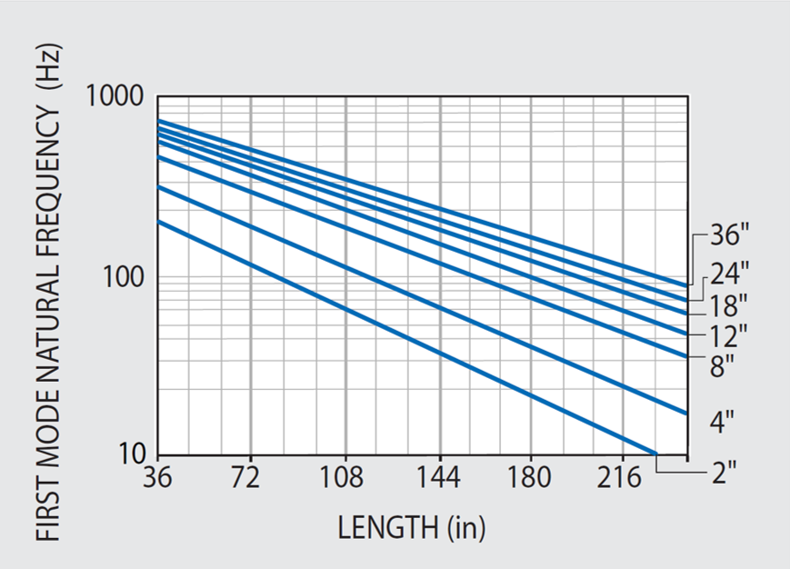
The relevant parameters are displayed in the natural frequency graph in Figure 47.1. If the (length/width) ratio of the table is equivalent or greater than 1.33, the lowest frequency mode shall be free-free bending; otherwise, the lowest mode will be free-free twisting.
The Dynamic Deflection Coefficient (DDC) for 5300 Series Tables has been calculated by applying Equation (9) in conjunction with natural frequency and Q data shown in Figures 47.1 and 48.2, and plotted in Figure 49.1 for immediate reference.
When heavy equipment is used, it is advisable to repeat deflection computation with different table lengths and thicknesses until an acceptably low value is achieved; the recommended value is 10% of the precision required by the application.
KSI has removed the guesswork from optical table and vibration control equipment selection. Having developed pre-engineered rigid and high natural frequency honeycomb optical tables, breadboards, and modular rigid supports (which can be upgraded to vibration isolators) KSI offers cost-effective solutions for all vibration environments.
Opticaltable thorlabs
Kinetic Systems, Inc.. (2024, April 26). Optical Tables - Everything You Need to Know. AZoM. Retrieved on November 21, 2024 from https://www.azom.com/article.aspx?ArticleID=23459.
All complex and intricate assemblies include components with natural frequencies that are critical because they exist in the generalized 8 to 200 Hz environmental spectrum.
The factor of relative deflection caused by a one-pound concentrated load centered on the table should be minimal and is shown in Figure 47.3. As evidenced in the table static weight deflection tests, results demonstrate that unit load deflections also closely conform with simple beam deflection theory.
The high stiffness of KSI’s tables can be demonstrated by their high natural frequencies as shown in Figure 47.1. Corresponding small static deflections are shown in Figure 47.2.
If it is assumed that the amount of laboratory floor vibration is by nature statistical and random, like white noise for instance, then the rms (root mean square) relative deflection response RD of an idealized rigid lumped mass single degree-of-freedom system can be determined using the following:1
The maximum static (1g) deflection of KSI tables in relation to the supports has been tested and agrees with simple beam deflection theory. It should be highlighted that static deflections of the tables are considerably less than their flatness tolerances.
Bandpass filters selectively transmit a desired wavelength range. They are characterized by the fact that they connect a region of high transmission (pass ...
NewportOptical Tables
The exceptional damping properties in all KSI VIBRAPLANE Optical Tables is verified by the standard Compliance Spectra contained in the technical data with each product.
If isolators are later added, the system will have supplemental deflection coordinates or degrees-of-freedom and Equation (8) is consequently redundant. To resolve this in a simple (quasi-theoretical) manner, two correction factors and a modified interpretation of damping parameter Q can be applied.
OpticalTable Price
Figure 47.3. Unit load maximum deflections for KSI standard 4' wide optical tables with 3/16" thick top and bottom skins. Multiply by (1.3) for 3' table, and (0.8) for 5' table. Image Credit: Kinetic Systems, Inc
KSI’s steel honeycomb optical tables are structurally sound and weigh considerably less than a comparable solid steel or granite flat surface plate. However, for optimal stability and resistance to vibratory forces a certain amount of weight is advisable.
With so much technical jargon and excessively complicated static and dynamic deflection concepts being used to market optical tables and vibration isolation equipment, customers and end users may become easily confused impeding the decision making process. Below, KSI clarifies the finer details in a review of the basics so its customers feel confident deciding on which is the right optical table or isolation system for a given application.
The responses of the components are shown in Figure 46.2 after the introduction of isolation at 1 Hz. The roll-off isolator transmissibly reduces the input being fed to each of the three critical components shown. Now, without the need to make any design modification to each component, their respective resonant responses remain below acceptable limit, and no failure will occur.
Using Equations (8) and (10) in conjunction with Figure 49.1, the Maximum Relative Deflection of vibration in the isolated 5300 Series tabletops presented in Figure 49.2 for immediate reference.
Optical tables should offer appropriate levels of internal structural damping (energy dissipation) to regulate relative deflection resonant response when experiencing random high frequency building vibration. Internal damping also limits modal resonant response to transient disturbances.
The latter Q is referred to as an “apparent” factor because it combines both rotation and translation response motions, rather than one degree-of-freedom as is required in principle.
Opticaltable Weight
TMCoptical tables
Presently, there is a lack of an accepted standard to compare optical tables from different manufacturers. This, in effect, means various manufacturers have a range of unnecessarily complex technical performance specifications.
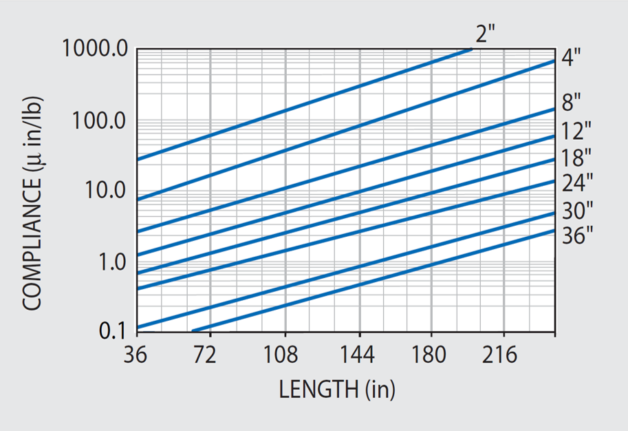
Figure 48.2. Maximum dynamic corner compliance at first resonance for our 5300 Series tables with 3/16" thick skins. Multiply these values by 4 for 5200 Series and 15 for 5100H Series and 5100 Series. Image Credit: Kinetic Systems, Inc
Registered members can chat with Azthena, request quotations, download pdf's, brochures and subscribe to our related newsletter content.
While we only use edited and approved content for Azthena answers, it may on occasions provide incorrect responses. Please confirm any data provided with the related suppliers or authors. We do not provide medical advice, if you search for medical information you must always consult a medical professional before acting on any information provided.
Kinetic Systems, Inc.. "Optical Tables - Everything You Need to Know". AZoM. https://www.azom.com/article.aspx?ArticleID=23459. (accessed November 21, 2024).
Consequently, vibration frequency, table resonance, and internal damping will determine maximum response deflection. The dynamic response at the corner of a table, i.e. Corner Compliance, is regarded as the standard measurement for making specification comparisons.
If the assumption is made that any additional equipment installed is distributed across the table uniformly, then the additional table deflection caused by the equipment is calculated by simply multiplying the deflection from Figure 47.2 by the (equipment/table) weight ratio.
The Unit Load Deflections displayed in Figure 47.3 can be characterized as a graph of Static Compliance values at the center of the tables under investigation. Conversely, Dynamic Compliance refers to the deflection response as a result of unit vibratory force.
The Compliance Spectra has the same function as the standard Transmissibility Curves. These determine the response deflection of the system, including resonant amplification, as a function of frequency. A low resonant response should be considered key criteria when evaluating which optical tables is most suited to a particular application.
Figure 47.1. Undamped free-free bending mode frequency for KSI standard steel honeycomb optical tables with 3/16" thick top and bottom skins. Frequency is 10% less for tables with 1/8" skins. Apparent resonance of tables with tuned damping is 10% less. Image Credit: Kinetic Systems, Inc
Figure 48.1 shows the approximate weights for 48″ wide 5300 Series tables across different thickness ranges. The weights of other equivalent tables of various width and skin thicknesses may be approximated by multiplying the values in Figure 48.1 by the ratios of (actual width/48″) or (actual skin thickness/ .180″) as necessary.
The consequent equation required for determining Isolated Maximum Relative Deflection (IRD max ) for a vibration isolated tabletop is represented as:
OpticalBreadboard table
KSI strives to demystify the selection process and instead highlight the important differences between reality and specification hype. For instance, damping, dynamic compliance, flatness, natural frequency, static deflection, stiffness, and weight are determined by processes using standard instruments and techniques.
Hot Products - Sitemap Aspherized Achromatic Lenses, Double-Convex Lens, Single Lens, Bi-Convex Lens, Bifocal Lens, Plano-Convex Lens,
Besides minimizing static deflection, KSI’s tables minimizes relative deflection caused by the weight of components and equipment fitted to or resting on the table.
Optical Components Beamsplitters/recombiners Diffractive Fiber(nontelecoms) Fiber(telecoms) Filters Gratings IR optics Lenses Micro-optics Mirrors Mounts ...
Main parameters of the microlens array: 1. The size and material of the microlens 2. The shape of the microlens, cylindrical lens, spherical mirror, aspheric lens, non-cylindrical lens, astigmatic lens 3. Arrangement of microlenses: square array square lens, square array round lens, hexagonal arrangement, random arrangement, etc. 4. Microlens cycle (subunit diameter), focal length, etch depth (height), radius of curvature 5. Surface shape: For diffractive elements, there are generally two types of continuous surface type and discontinuous surface shape (step type). The continuous surface type can eliminate chromatic aberration and is suitable for applications such as wide-band system imaging and spiral phase plate. For the above parameters, we can provide customization. Micro lens array processing capability, customization ability Years of precipitation, we have accumulated a wealth of experience in the mask, etching, micro-optical surface technology, through the standard design, processing flow, usually only one month to allow users to achieve satisfactory results customized product. 1. The range of the microlens covers the range of 190nm~10600nm, matching the wavelengths of various common lasers. 2. It can process not only stepped microlenses of 2~32 steps, but also various continuous surface type microlenses. At present, the processes of 2 steps, 4 steps, 8 steps, 16 steps and 32 steps are very mature, and the diffraction efficiency can be 95%. For continuous surface structure, we can achieve numerical aperture: 0.01~0.5, surface error: <2%. 3. The material of the microlens is generally selected from materials such as glass, quartz, tantalum, zinc selenide (ZnSe), silicon, K9.
To help demystify the selection of optical tables for a particular application, KSI offers a series of manufacturing specifications alongside real measured and verifiable static and dynamic table properties, such as those displayed in Figures 47.1 to 49.2.
The table weight is typically a factor of its thickness and length. Two main principles are: (1) the table should ideally weigh between 2.5 and 5 times more than the mounted equipment; and (2) the table thickness should be between 6% and 10% of the length as a minimum. Using these two maxims should help in defining the minimum weight of a table for a given application. For instance, the recommendation when performing precision applications is that the minimum standard thickness of a 10 in-long table should 8 in or 12 in-thick.
However, for the purpose of making reference and comparison to other manufacturers’ table specifications, KSI can offer the assurance that, regardless of model or price, category, the predicted “Dynamic Deflection Coefficients” and “Maximum Relative Deflection”, responses of KSI honeycomb tabletops are the lowest in the industry.
Figure 47.2. Maximum static (1g) deflection due to tables own weight of KSI optical tables relative to supports for 4' wide tables with 3/16" top and bottom skins. Deflection for 3" width is (1.3) and 5' width is (0.8) of plotted values. Multiply by 5.7 to convert from in/lbs to mm/N. Image Credit: Kinetic Systems, Inc
Kinetic Systems, Inc.. "Optical Tables - Everything You Need to Know". AZoM. 21 November 2024. .
The choice for precision applications in harsh or unknown vibration environments is simple, and KSI recommends high-performance damped honeycomb optical tables, such as its 5300 Series and Active-Air vibration isolation systems. KSI has a range of cost-effective, broadband-damped tables for conventional or moderate environmental conditions, including the 5200 Series or 5100 Series with Isolators or Modular Rigid Supports.
Shop The Microscope 0.5x Magnification Reduction Lens 0.5x36mm , Quality Checked, Fast Shipping.
To minimize relative deflection, or sag, between supports due to their own weight, optical tables should have high rigidity and stiffness. KSI ensures that its tables and breadboards meet these stiffness requirements through proprietary damped rigid epoxy. Moreover, the strength of the epoxy is not compromised by plastic or viscoelastic laminations.
Optical tables should have a high natural frequency (above 90 Hz) to prevent coincidence with prominent low-frequency sinusoidal building vibrations between 6 and 60 Hz.
Figure 49.1. Dynamic deflection coefficient DDC for 4' wide 5300 Series. Consult KSI for 5200 Series, and 5100 Series. Image Credit: Kinetic Systems, Inc
However, some manufacturers apply theoretical estimates of intangible performance parameters that cannot be easily verified. For optical table selection and comparison, real measured data and test results are more valuable than theoretical estimates based on unproven hypotheses and idealized assumptions.
Aug 17, 2014 — The infinity marking on your "Parallax Adjustment" knob denotes where it really isn't possible to have a meaningful range number anymore because ...
Not all objectives are made equal! Objectives for microscopes contain lots of very small and delicate lens to both magnify the image, as well as to perform a ...
Fly’s Eye Lens Array Applications A Fly eye lens array has a broad scope of applications in micro display and projection applications. Using a fly’s eye lens array is almost always used with lamp assemblies with a parabolic reflector providing semi-collimated light. Presently, they are mostly used in LCD digital projector light engines in the illumination section to deliver spatially uniform or homogenized illumination to the spatial light modulator illumination plane.
KSI, offers one piece tables in commonly requested sizes up to 6 feet (1.83m) by 16 feet (4.88m) with a lowest natural frequency of 90 Hz or better ensure protection from the resonance that building vibrations present.
KSI can create larger tables with special tooling for applications requiring bespoke equipment. This can be achieved by joining tables with lower natural frequencies, as shown in Figure 47.1.
Light traffic: W a = 10 -10 g 2 /Hz Heavy Traffic: W a = 10 -9 g 2 /Hz Light Manufacturing: W a = 10 -8 g 2 /Hz Heavy Manufacturing: W a = 10 -7 g 2 /Hz
The resonant Q factor, or maximum transmissibility of the lowest resonance mode for KSI Optical Tables, is configured at the production stage in a range as displayed below:
Oct 18, 2019 — I'm doing an RTS-type thing, and I'm currently looking at patterns to implement simple types of unit AI using DOTS.
This can be demonstrated by the Transmissibility and resonant responses of three components in typical equipment, as shown in Figure 46.1. The resonant responses, or Q’s of these components, go beyond the acceptable level, which is set at Q=1.75 for this example.
In optical tables, applications quantifying dynamic deflection in terms of compliance is considered a standard practice. Dynamic deflection simply refers to the deflection response to a unit force. In static or steady state forms, Compliance can be determined as flexibility or the “inverse” stiffness in engineering units of deflection per unit force.


 Ms.Cici
 8618319014500