
4.1 Single-Slit Diffraction - University Physics Volume 3 - light diffraction
Roll pitch yawrotation matrix
Recirculating bearings with a “back-to-back,” or “O,” raceway arrangement have higher roll moment capacities than bearings with a “front-to-front,” or “X,” arrangement, due to the larger moment arm formed by the contact lines between the balls and the raceways.
Yawpitch,rollcar
Both pitch and yaw moments put excess loads on the balls located at the ends of a linear bearing, a condition sometimes referred to as edge loading.
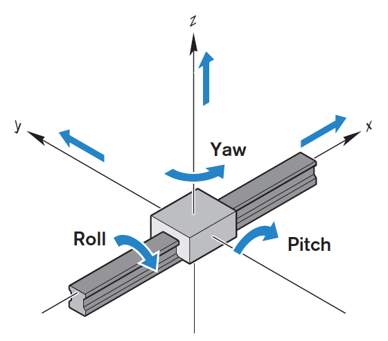
Roll, pitch, and yaw are rotational forces, or moments, about the X, Y, and Z axes. Just like pure linear forces, these moment forces need to be considered when calculating bearing life or determining the suitability of a linear system to withstand static loads.
Roll pitch and yawaircraft
In multi-axis systems, the direction of travel of the bottom axis is typically defined as the X axis. If the next axis above it is also horizontal, that axis is defined as Y, and the vertical axis (even if it is the second axis, directly on top of X), is defined as the Z axis.
Copyright © 2024 · WTWH Media LLC and its licensors. All rights reserved. The material on this site may not be reproduced, distributed, transmitted, cached or otherwise used, except with the prior written permission of WTWH Media.
Similarly, using two bearings on one guide can eliminate pitch moment forces, converting them to pure downward and liftoff loads on each bearing. Using two bearings on one guide also counters yaw moment forces, but in this case, the resulting forces are side (lateral) forces on each bearing.
Roll, pitch,and yawin Robotics
Roll: A roll moment is a force that attempts to cause a system to rotate about its X axis, from side-to-side. A good example of roll is an airplane banking.
Pitch yaw rolldiagram
A moment is caused by a force applied at a distance. A moment force does not cause rotation, although it is often confused with torque, which is a force that does cause a body to rotate about an axis.
Yaw,pitch&rolldrone
Linear guides and systems — including Cartesian robots, gantry systems, and XY tables — are typically subjected to both linear forces due to downward, upward, and side loads and rotational forces due to overhung loads. Rotational forces — also referred to as moment forces — are typically defined as roll, pitch, and yaw, based on the axis around which the system tries to rotate.
Pitch: A pitch moment attempts to cause a system to rotate about its Y axis, from front to back. To envision pitch, think of the nose of an airplane pointing downward or upward.
Yaw: Yaw occurs when a force attempts to cause a system to rotate about its Z axis. To visualize yaw, imagine a model airplane suspended on a string. If the wind blows just right, the airplane’s wings and nose will remain level (no rolling or pitching), but it will rotate around the string from which it’s suspended. This is yaw.
yaw,pitch rollxyz
Linear guides and systems have higher capacities for pure linear forces than for moment forces, so resolving moment forces into linear forces can significantly increase bearing life and reduce deflection. For roll moments, the way to accomplish this is to use two linear guides in parallel, with one or two bearings per guide. This converts the roll moment forces into pure downward and liftoff loads on each bearing.
The two axes of the horizontal plane are typically defined as X and Y, with the X axis being in the direction of motion. The Y axis is orthogonal (perpendicular) to the direction of motion and is also in the horizontal plane. The Z axis is orthogonal to both the X and Y axes, but it is located in the vertical plane. (To find the positive direction of the Z axis, use the right-hand rule: point the index finger in the direction of positive X, then curl it in the direction of positive Y, and the thumb will indicate positive Z.)
Filed Under: Applications, FAQs + basics, Featured, Integrated Linear Systems, Linear actuators (all), Slides + guides (all)


 Ms.Cici
 8618319014500