
2024 Fresnel Lens Series - solar fresnel lens
See, hear, and touch the latest innovations, connect with technology experts, and receive hands-on training at one of our 18 spaces across the Americas.
In practice, modern microscopes contain a series of lenses rather than just one. They have an objective lens (which sits close to the object) and an eyepiece lens (which sits closer to your eye). Both of these contribute to the magnification of the object. The eyepiece lens usually magnifies 10x, and a typical objective lens magnifies 40x. (Microscopes usually come with a set of objective lenses that can be interchanged to vary the magnification.) You can calculate the total magnifying power of the microscope by multiplying the magnifying powers of the objective lens and the eyepiece (so 10 x 40 = total magnification of 400x).
Although the eye is marvelous in its ability to see objects large and small, it obviously has limitations to the smallest details it can detect. Human desire to see beyond what is possible with the naked eye led to the use of optical instruments. In this section we will examine microscopes, instruments for enlarging the detail that we cannot see with the unaided eye. The microscope is a multiple-element system having more than a single lens or mirror. (See Figure 1.) A microscope can be made from two convex lenses. The image formed by the first element becomes the object for the second element. The second element forms its own image, which is the object for the third element, and so on. Ray tracing helps to visualize the image formed. If the device is composed of thin lenses and mirrors that obey the thin lens equations, then it is not difficult to describe their behavior numerically.
To get around this issue, scientists designed an alternative lens – a coil of wire surrounding the electron beam. When electricity runs through the wire, it generates a magnetic field within the coil. Because electrons are charged, the microscope’s electron beam bends in response to the magnetic field as it passes through the coil. In this way, the coils act as lenses – they bend the electron beam, just as glass lenses bend light in an optical microscope.
[latex]m_{\text{e}}=-\frac{d_{\text{i}}\prime}{d_{\text{o}}\prime}=-\frac{-367\text{ mm}}{44.0\text{ mm}}=8.33\\[/latex].
where do and di are the object and image distances, respectively, for the objective lens as labeled in Figure 2. The object distance is given to be do=6.20 mm, but the image distance di is not known. Isolating di, we have
Dec 26, 2010 — Multi monitor setup with fresnel lens tutorial. For those who are not familiar with multi monitor setup with Matrox TH2Go: I have made a video ...
Makro · SIGMA 105mm F2,8 DG DN MACRO | Art · Cashback 80€ · SIGMA 105mm F2,8 DG DN MACRO | Art · SIGMA 70mm F2,8 DG MACRO | Art · SIGMA MAKRO 105mm F2,8 EX DG ...
How does a microscopemagnify
numerical aperture: a number or measure that expresses the ability of a lens to resolve fine detail in an object being observed. Derived by mathematical formula NA = n sin α, where n is the refractive index of the medium between the lens and the specimen and [latex]\alpha=\frac{\theta}{2}\\[/latex]
Microscope
Flir Camera Quasar Fixed Box 4K Cs Lens Mount · High performance True Day/Night camera · 4K @ 30 fps or 1080p @ 60 fps with Enhanced Low Light Performance mode ...
This activity and interactive involve identifying and labelling the main parts of a microscope and describing their function.
Learn about achromatic color scheme in design and see how it is used in various rooms and for accessories. Compare the achromatic meaning to...
Our dedicated team of experts is equipped with the latest tools and knowledge to handle repairs on a wide range of laser systems. We prioritize transparency and ...
Including more lenses doesn’t change the basic principle of how a microscope magnifies but it does enable higher magnifications and gives a better quality image.
The term f/# in general is called the f-number and is used to denote the light per unit area reaching the image plane. In photography, an image of an object at infinity is formed at the focal point and the f-number is given by the ratio of the focal length f of the lens and the diameter D of the aperture controlling the light into the lens (see Figure 3b). If the acceptance angle is small the NA of the lens can also be used as given below.
How does a microscopework step by step
Figure 3. (a) The numerical aperture of a microscope objective lens refers to the light-gathering ability of the lens and is calculated using half the angle of acceptance . (b) Here, is half the acceptance angle for light rays from a specimen entering a camera lens, and is the diameter of the aperture that controls the light entering the lens.
... GRID PANEL, SOLD IN PAIRS. $35.99 · Quick view. 12"X12"H BLACK "L" LEGS FOR GRID ... WIRE SHELF WITH FRONT LIP BLACK 15"X24" FOR GRIDWALL PANEL. $36.99 · Quick ...
Convert 38.1 Millimeters to Inches | Convert 38.1 mm to in with our conversion calculator and conversion table.
How Does a microscopeWork for Kids
compound microscope: a microscope constructed from two convex lenses, the first serving as the ocular lens(close to the eye) and the second serving as the objective lens
When using a microscope we do not see the entire extent of the sample. Depending on the eyepiece and objective lens we see a restricted region which we say is the field of view. The objective is then manipulated in two-dimensions above the sample to view other regions of the sample. Electronic scanning of either the objective or the sample is used in scanning microscopy. The image formed at each point during the scanning is combined using a computer to generate an image of a larger region of the sample at a selected magnification.
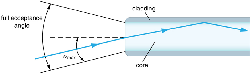
Figure 4. Light rays enter an optical fiber. The numerical aperture of the optical fiber can be determined by using the angle αmax.
Figure 2. A compound microscope composed of two lenses, an objective and an eyepiece. The objective forms a case 1 image that is larger than the object. This first image is the object for the eyepiece. The eyepiece forms a case 2 final image that is further magnified.
[latex]\displaystyle\frac{1}{d_{\text{i}}\prime}=\frac{1}{f_{\text{e}}}-\frac{1}{d_{\text{o}}\prime}=\frac{1}{50.0\text{ mm}}-\frac{1}{44.0\text{ mm}}=\frac{0.00273}{\text{mm}}\\[/latex]
Figure 6. Illumination of a specimen in a microscope. (a) Transmitted light from a condenser lens. (b) Transmitted light from a mirror condenser. (c) Dark field illumination by scattering (the illuminating beam misses the objective lens). (d) High magnification illumination with reflected light – normally laser light.
While the numerical aperture can be used to compare resolutions of various objectives, it does not indicate how far the lens could be from the specimen. This is specified by the “working distance,” which is the distance (in mm usually) from the front lens element of the objective to the specimen, or cover glass. The higher the NA the closer the lens will be to the specimen and the more chances there are of breaking the cover slip and damaging both the specimen and the lens. The focal length of an objective lens is different than the working distance. This is because objective lenses are made of a combination of lenses and the focal length is measured from inside the barrel. The working distance is a parameter that microscopists can use more readily as it is measured from the outermost lens. The working distance decreases as the NA and magnification both increase.
A microscope is something that uses a lens or lenses to make small objects look bigger and to show more detail. This means that a magnifying glass can count as a microscope! It also means that making your own microscope is straightforward.
To see how the microscope in Figure 2 forms an image, we consider its two lenses in succession. The object is slightly farther away from the objective lens than its focal length fo, producing a case 1 image that is larger than the object. This first image is the object for the second lens, or eyepiece. The eyepiece is intentionally located so it can further magnify the image. The eyepiece is placed so that the first image is closer to it than its focal length fe. Thus the eyepiece acts as a magnifying glass, and the final image is made even larger. The final image remains inverted, but it is farther from the observer, making it easy to view (the eye is most relaxed when viewing distant objects and normally cannot focus closer than 25 cm). Since each lens produces a magnification that multiplies the height of the image, it is apparent that the overall magnification m is the product of the individual magnifications: m = mome, where mo is the magnification of the objective and me is the magnification of the eyepiece. This equation can be generalized for any combination of thin lenses and mirrors that obey the thin lens equations.
As the f-number decreases, the camera is able to gather light from a larger angle, giving wide-angle photography. As usual there is a trade-off. A greater f/# means less light reaches the image plane. A setting of f/16 usually allows one to take pictures in bright sunlight as the aperture diameter is small. In optical fibers, light needs to be focused into the fiber. Figure 4 shows the angle used in calculating the NA of an optical fiber.
We normally associate microscopes with visible light but x ray and electron microscopes provide greater resolution. The focusing and basic physics is the same as that just described, even though the lenses require different technology. The electron microscope requires vacuum chambers so that the electrons can proceed unheeded. Magnifications of 50 million times provide the ability to determine positions of individual atoms within materials. An electron microscope is shown in Figure 7.
This situation is similar to that shown in Figure 2. To find the overall magnification, we must find the magnification of the objective, then the magnification of the eyepiece. This involves using the thin lens equation.
Figure 8. The image shows a sequence of events that takes place during meiosis. (credit: PatríciaR, Wikimedia Commons; National Center for Biotechnology Information)
The commitment to excellence of Nova Gas is unsurpassed and its state of the art production facility allows it to provide customers with the highest quality ...
Microscopes were first developed in the early 1600s by eyeglass makers in The Netherlands and Denmark. The simplest compound microscope is constructed from two convex lenses as shown schematically in Figure 2. The first lens is called the objective lens, and has typical magnification values from 5× to 100×. In standard microscopes, the objectives are mounted such that when you switch between objectives, the sample remains in focus. Objectives arranged in this way are described as parfocal. The second, the eyepiece, also referred to as the ocular, has several lenses which slide inside a cylindrical barrel. The focusing ability is provided by the movement of both the objective lens and the eyepiece. The purpose of a microscope is to magnify small objects, and both lenses contribute to the final magnification. Additionally, the final enlarged image is produced in a location far enough from the observer to be easily viewed, since the eye cannot focus on objects or images that are too close.
Whatdoes a microscopedo
How Does a microscopeWork simple
When using a microscope, we rely on gathering light to form an image. Hence most specimens need to be illuminated, particularly at higher magnifications, when observing details that are so small that they reflect only small amounts of light. To make such objects easily visible, the intensity of light falling on them needs to be increased. Special illuminating systems called condensers are used for this purpose. The type of condenser that is suitable for an application depends on how the specimen is examined, whether by transmission, scattering or reflecting. See Figure 6 for an example of each. White light sources are common and lasers are often used. Laser light illumination tends to be quite intense and it is important to ensure that the light does not result in the degradation of the specimen.
How doeslight limit the detail inalightmicroscope
We do not use our eyes to form images; rather images are recorded electronically and displayed on computers. In fact observing and saving images formed by optical microscopes on computers is now done routinely. Video recordings of what occurs in a microscope can be made for viewing by many people at later dates. Physics provides the science and tools needed to generate the sequence of time-lapse images of meiosis similar to the sequence sketched in Figure 8.
Figure 7. An electron microscope has the capability to image individual atoms on a material. The microscope uses vacuum technology, sophisticated detectors and state of the art image processing software. (credit: Dave Pape)
Look through a clear glass or plastic bottle and describe what you see. Now fill the bottle with water and describe what you see. Use the water bottle as a lens to produce the image of a bright object and estimate the focal length of the water bottle lens. How is the focal length a function of the depth of water in the bottle?
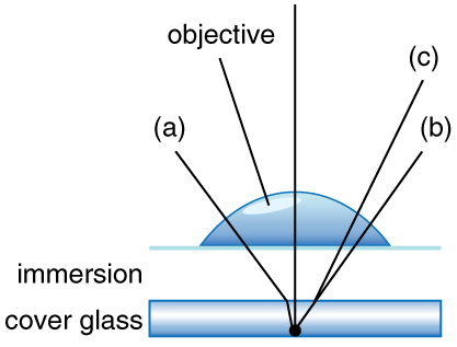
Figure 5. Light rays from a specimen entering the objective. Paths for immersion medium of air (a), water (b) (n = 1.33), and oil (c) (n = 1.51) are shown. The water and oil immersions allow more rays to enter the objective, increasing the resolution.
Normal optical microscopes can magnify up to 1500× with a theoretical resolution of −0.2 μm. The lenses can be quite complicated and are composed of multiple elements to reduce aberrations. Microscope objective lenses are particularly important as they primarily gather light from the specimen. Three parameters describe microscope objectives: the numerical aperture (NA), the magnification (m), and the working distance. The NA is related to the light gathering ability of a lens and is obtained using the angle of acceptance θ formed by the maximum cone of rays focusing on the specimen (see Figure 3a) and is given by NA = n sin α, where n is the refractive index of the medium between the lens and the specimen and [latex]\alpha=\frac{\theta}{2}\\[/latex]. As the angle of acceptance given by θ increases, NA becomes larger and more light is gathered from a smaller focal region giving higher resolution. A 0.75 NA objective gives more detail than a 0.10 NA objective.
Can the NA be larger than 1.00? The answer is ‘yes’ if we use immersion lenses in which a medium such as oil, glycerine or water is placed between the objective and the microscope cover slip. This minimizes the mismatch in refractive indices as light rays go through different media, generally providing a greater light-gathering ability and an increase in resolution. Figure 5 shows light rays when using air and immersion lenses.
Very early microscopes were extremely simple but were still remarkably good at magnifying small objects. For instance, microscopes made by the Dutchman Antonie van Leeuwenhoek in the 1600s were merely a small glass ball (which acted as a lens) set into a metal frame. Using this simple apparatus, van Leeuwenhoek discovered the world of what he called ‘animalcules’ (microorganisms) – tiny single-celled creatures that are far too small to be seen with the naked eye.
Whatdoes astage do ina microscope
Now we must find the magnification of the eyepiece, which is given by [latex]m_{\text{e}}=-\frac{d_{\text{i}}\prime}{d_{\text{o}}\prime}\\[/latex], where di′ and do′ are the image and object distances for the eyepiece (see Figure 2). The object distance is the distance of the first image from the eyepiece. Since the first image is 186 mm to the right of the objective and the eyepiece is 230 mm to the right of the objective, the object distance is do′ = 230 mm − 186 mm = 44.0 mm. This places the first image closer to the eyepiece than its focal length, so that the eyepiece will form a case 2 image as shown in the figure. We still need to find the location of the final image di′ in order to find the magnification. This is done as before to obtain a value for [latex]\frac{1}{d_{\text{i}}\prime}\\[/latex]:
Microscope lenses differ widely in quality, and this can affect how clearly you can see an image. The quality of the glass used and the shape of the lens both affect its overall quality. Misalignment of lenses within the microscope can also limit resolution. In practice, this means that students using classroom microscopes may not be able to view samples that are close to the theoretical limits of resolution of a light microscope.
The optical polarization is a typical non-equilibrium quantity that decays to zero when a system relaxes to its equilibrium state. Coherent effects are ...
When you look through a simple light microscope or a magnifying glass, you are looking through a biconvex lens (one that’s bent like the back of a spoon on both sides) made of glass. The object being viewed is on the far side of the lens. Light from the object passes through the lens and is bent (refracted) towards your eye, so it seems as though it comes from a much bigger object.
Electron microscopes use a beam of electrons instead of visible light to illuminate the object being viewed. However, electrons can’t pass through glass, so the lenses that are used in light microscopes can’t be used to bend the electron beam.
Calculate the magnification of an object placed 6.20 mm from a compound microscope that has a 6.00 mm focal length objective and a 50.0 mm focal length eyepiece. The objective and eyepiece are separated by 23.0 cm.
Both the objective and the eyepiece contribute to the overall magnification, which is large and negative, consistent with Figure 2, where the image is seen to be large and inverted. In this case, the image is virtual and inverted, which cannot happen for a single element (case 2 and case 3 images for single elements are virtual and upright). The final image is 367 mm (0.367 m) to the left of the eyepiece. Had the eyepiece been placed farther from the objective, it could have formed a case 1 image to the right. Such an image could be projected on a screen, but it would be behind the head of the person in the figure and not appropriate for direct viewing. The procedure used to solve this example is applicable in any multiple-element system. Each element is treated in turn, with each forming an image that becomes the object for the next element. The process is not more difficult than for single lenses or mirrors, only lengthier.
Some modern instruments that don’t contain lenses are still known as microscopes because they magnify objects. For example, the scanning tunnelling microscope and the atomic force microscope measure the shape of a surface by measuring the distance between the microscope’s probe and the surface. These microscopes generate images at very high resolution. You can learn more about them in the article Nanoscience that introduces our wide range of nanoscience resources.
5. (a) +18.3 cm (on the eyepiece side of the objective lens); (b) −60.0; (c) −11.3 cm (on the objective side of the eyepiece); (d) +6.67; (e) −400
You’ll meet some highly complex microscopes in our collection of microscope resources, but most of them are just ways of viewing objects in more detail with lenses. A lot of technological innovations have been added to microscopes over time (mostly to make them simpler to use and improve the quality of the images seen). These changes can make microscopes appear more complicated, but they don’t alter the basic science of the microscope lenses.


 Ms.Cici
 8618319014500