
Beko Gas Built-In Hob 4 Burners - Black - HIAW 64225 BX - 2B - bx built
Focaldistance vsfocal length
SWIR - BAR LIGHT - Model Colour Voltage (V) / Watt (W) Current Weight (g) HLBS2-00-325-1-3SWIR-12V IR1050 / IR1250 / IR1500.
A 360-degree view dash cam is a game-changer for drivers who want to capture every detail around their vehicle. These advanced cameras come packed with features ...
Zebra's VisibilityIQ Foresight is a cloud based solution that aggregates data from MDM and other device data sources to provide you with the business ...
Focal lengthcamera
While most sensors are 4:3, 5:4 and 1:1 are also quite common. This distinction in aspect ratio also leads to varying dimensions of sensors of the same sensor format. All of the equations used in this section can also be used for vertical FOV as long as the sensor’s vertical dimension is substituted in for the horizontal dimension specified in the equations.
Generally, lenses that have fixed magnifications have fixed or limited WD ranges. While using a telecentric or other fixed magnification lens can be more constraining, as they do not allow for different FOVs by varying the WD, the calculations for them are very direct, as shown in Equation 4.
Be aware that Equation 6 is an approximation and will rapidly deteriorate for magnifications greater than 0.1 or for short WDs. For magnifications beyond 0.1, either a fixed magnification lens or computer simulations (e.g. Zemax) with the appropriate lens model should be used. For the same reasons, lens calculators commonly found on the internet should only be used for reference. When in doubt, consult a lens specification table.
The focal length of a lens is a fundamental parameter that describes how strongly it focuses or diverges light. A large focal length indicates that light is bent gradually while a short focal length indicates that the light is bent at sharp angles. In general, lenses with positive focal lengths converge light while lenses with negative focal lengths cause light to diverge, although there are some exceptions based on the distance from the lens to the object being imaged.
Field of view describes the viewable area that can be imaged by a lens system. This is the portion of the object that fills the camera’s sensor. This can be described by the physical area which can be imaged, such as a horizontal or vertical field of view in mm, or an angular field of view specified in degrees. The relationships between focal length and field of view are shown below.

While it may be convenient to have a very wide AFOV, there are some negatives to consider. First, the level of distortion that is associated with some short focal length lenses can greatly influence the actual AFOV and can cause variations in the angle with respect to WD due to distortion. Next, short focal length lenses generally struggle to obtain the highest level of performance when compared against longer focal length options (see Best Practice #3 in Best Practices for Better Imaging). Additionally, short focal length lenses can have difficulties covering medium to large sensor sizes, which can limit their usability, as discussed in Relative Illumination, Roll-Off, and Vignetting.
In general, however, the focal length is measured from the rear principal plane, rarely located at the mechanical back of an imaging lens; this is one of the reasons why WDs calculated using paraxial equations are only approximations and the mechanical design of a system should only be laid out using data produced by computer simulation or data taken from lens specification tables. Paraxial calculations, as from lens calculators, are a good starting point to speed the lens selection process, but the numerical values produced should be used with caution.
Focal length
Bright Field Studios is an award-winning interdisciplinary practice of architects based in London, UK and Budapest, Hungary.
Note: Fixed focal length lenses should not be confused with fixed focus lenses. Fixed focal length lenses can be focused for different distances; fixed focus lenses are intended for use at a single, specific WD. Examples of fixed focus lenses are many telecentric lenses and microscope objectives.
When using fixed focal length lenses, there are three ways to change the FOV of the system (camera and lens). The first and often easiest option is to change the WD from the lens to the object; moving the lens farther away from the object plane increases the FOV. The second option is to swap out the lens with one of a different focal length. The third option is to change the size of the sensor; a larger sensor will yield a larger FOV for the same WD, as defined in Equation 1.
RGB controllers, RGB+W and RGB+WW controllers for multicolor LED lights from Armacost Lighting.
FOV tofocal length
\begin{align}\text{AFOV} & = 2 \times \tan^{-1} \left( {\frac{50 \text{mm}}{2 \times 200 \text{mm}}} \right) \\ \text{AFOV} & = 14.25° \end{align}
The brightness of a lens is decided by a combination of focal length and lens diameter. If the focal length of two lenses is the same, the lens with the larger ...
2023101 — VOTAN-056 Return of Darkness Ide -chan On the contrary Heehee was told Nanami Yokomiya Pov .
Focus distance
Focal lengthformula
The 14.25° derived in Example 1 (see white box below) can be used to determine the lens that is needed, but the sensor size must also be chosen. As the sensor size is increased or decreased it will change how much of the lens’s image is utilized; this will alter the AFOV of the system and thus the overall FOV. The larger the sensor, the larger the obtainable AFOV for the same focal length. For example, a 25mm lens could be used with a ½” (6.4mm horizontal) sensor or a 35mm lens could be used with a 2/3” (8.8mm horizontal) sensor as they would both approximately produce a 14.5° AFOV on their respective sensors. Alternatively, if the sensor has already been chosen, the focal length can be determined directly from the FOV and WD by substituting Equation 1 in Equation 2, as shown in Equation 3.
The focal length of a lens defines the AFOV. For a given sensor size, the shorter the focal length, the wider the AFOV. Additionally, the shorter the focal length of the lens, the shorter the distance needed to obtain the same FOV compared to a longer focal length lens. For a simple, thin convex lens, the focal length is the distance from the back surface of the lens to the plane of the image formed of an object placed infinitely far in front of the lens. From this definition, it can be shown that the AFOV of a lens is related to the focal length (Equation 1), where $ \small{f} $ is the focal length and $ \small{H} $ is the sensor size (Figure 1).
35mm equivalentfocal length
As previously stated, some amount of flexibility to the system’s WD should be factored in, as the above examples are only first-order approximations and they also do not take distortion into account.
If the required magnification is already known and the WD is constrained, Equation 3 can be rearranged (replacing $ \small{ \tfrac{H}{\text{FOV}}} $ with magnification) and used to determine an appropriate fixed focal length lens, as shown in Equation 6.
A fixed focal length lens, also known as a conventional or entocentric lens, is a lens with a fixed angular field of view (AFOV). By focusing the lens for different working distances (WDs), differently sized field of view (FOV) can be obtained, though the viewing angle is constant. AFOV is typically specified as the full angle (in degrees) associated with the horizontal dimension (width) of the sensor that the lens is to be used with.
focallength中文
I.S. FERMI MN. 71,8160. 2222 28995 SRIS01400G. MICHELANGELO BARTOLO. 71,8146 ... ITI "FERMI" CASTROVILLARI. 60,1346. 4238 23835 PGIC86600D. I.C. PERUGIA 3. 60 ...
In many applications, the required distance from an object and the desired FOV (typically the size of the object with additional buffer space) are known quantities. This information can be used to directly determine the required AFOV via Equation 2. Equation 2 is the equivalent of finding the vertex angle of a triangle with its height equal to the WD and its base equal to the horizontal FOV, or HFOV, as shown in Figure 2. Note: In practice, the vertex of this triangle is rarely located at the mechanical front of the lens, from which WD is measured, and is only to be used as an approximation unless the entrance pupil location is known.
201941 — ... allontanare l'oggetto che si sta guardando per metterlo meglio a fuoco. Con il passare degli anni, l'occhio mette sempre meno a fuoco gli ...
Once the required AFOV has been determined, the focal length can be approximated using Equation 1 and the proper lens can be chosen from a lens specification table or datasheet by finding the closest available focal length with the necessary AFOV for the sensor being used.
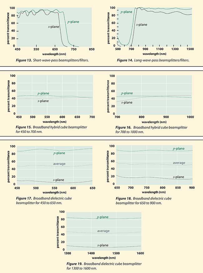
Plate beamsplitters Plate beamsplitters consist of a thin plate of optical crown glass with a different type of coating deposited on each side. The first surface is coated with an all-dielectric film having partial reflection properties over either the visible or the near-infrared spectrum. The benefit of this type of coating is that it has low absorption, typically 0.5 percent for a 50/50 splitter at 45°. The second surface has an antireflection coating optimized for 45°. The transmittance and reflectance curves shown in Figures 1 through 6 are for unpolarized inputs at an angle of incidence of 45°. As can be seen from the p- and s-polarization components of the transmitted beams, these beamsplitters are highly polarization sensitive. For clarity, only the average polarization reflectance curve has been presented. Nonpolarizing plate beamsplitters Nonpolarizing plate beamsplitters have been designed for use in situations in which the polarization characteristics of the incident laser radiation must be maintained in the reflected and transmitted beams. They may also be used to obtain a 50/50 split in laser energy (within tolerances) regardless of the polarization state of the incident beam. Such performance cannot be expected of other plate beamsplitter coatings since they are extremely polarization sensitive. Plate beamsplitters have a number of advantages over cube beamsplitters. Because they are devoid of optical cements that can absorb light energy, they can withstand significantly higher levels of laser power without damage. This is an important consideration when using moderate- or high-power lasers. Plate beamsplitters are also significantly smaller and lighter than their cube counterparts. In any application where size and weight constraints exist, plate beamsplitters are an option that should not be overlooked. The beamsplitter coating for these products is deposited on one side of a 3-mm-thick BK7 plate. The reverse side is coated with an antireflection coating whose reflectivity is only 0.5 percent at an angle of incidence of 45°. At their specific laser line wavelengths, these coatings reflect 50 ±5 percent of the incident radiation. When an unpolarized beam is incident on these coatings, the s- and p-components of the reflected (and the transmitted) beam are matched to within 3 percent. Because both the beamsplitter and antireflection coatings are all dielectric in composition, they have negligible absorption. These plate beamsplitters are designed for specific laser wavelengths (Figures 7 through 12). Long- and short-wavelength pass beamsplitters/filters Dielectric coatings acting as edge filters are very useful for many types of applications. Edge-filter coatings consist of modified λ/4 stacks. All dielectric in construction, their absorption is negligible. The edge filters described here are of both the short-wave- and the long-wave-pass varieties. They are wavelength-dependent beamsplitters, designed to be used at 45°. In the case of the long-wave-pass filter, the longer wavelengths are transmitted and the shorter wavelengths are reflected at 90° to the incident and transmitted beams. The opposite is true in the case of the short-pass design. Both of these beamsplitters/filters have their 50 percent edge centered around 700 nm (Figures 13 and 14). They are both ideal for separating short-wave diode laser radiation from visible light. In addition, the long-wave-pass filter has high transmission out to 1600 nm, making it suitable for the longer wavelength telecommunications diodes. Long-wave-pass beamsplitters/ filters may be fabricated from BK7 substrates and coated on both sides. The front surface is coated with an edge transmission coating that reflects light in the 550- to 650-nm range and transmits from 760 to 1600 nm. The rear surface is coated with a broadband antireflection coating. They should be used at incidence angles of 45° ±5°. Short-wave-pass beamsplitters/filters also consist of a BK7 substrate with a rear-surface broadband antireflection coating. The front-surface coating transmits visible light (450 to 650 nm) and reflects 760- to 850-nm wavelength radiation. They should be used at incidence angles of 45° ±5°. Cube beamsplitters Cube beamsplitters have several advantages over plate beamsplitters and are widely used for a variety of reasons. These are rugged beamsplitters that are easy to mount and are ideal for beam superposition applications. This type of beamsplitter deforms much less when subjected to mechanical stress than does a plate beamsplitter. Most of the unwanted reflections from a cube beamsplitter are in the retrodirection and do not contribute to ghost images. The coating is very resistant to degradation with time because it is sealed within the body of the cube. You may also like...LaCroix Precision Optics Adds Assembly, Design DepartmentsNew Ideas Reshape Beam ShapingBeamsplitter Benefits from Topological Antichiral Edge StatesThe Rise of Micro-Optics Shows No Sign of SlowingIf cube beamsplitters are used in convergent or divergent portions of an optical beam, they will contribute substantial amounts of unwanted aberration. This can be avoided or minimized by using these components only with collimated or nearly collimated beams. Conjugate distances that include cubes, therefore, should be long. Alternately, other elements of the system can be designed to compensate for any aberrations introduced by the cube in a noncollimated beam. Cube beamsplitters consist of matched pairs of identical right-angle prisms with their hypotenuse faces cemented together. Prior to cementing, a partial reflection film is deposited onto one of the faces. For best results, the incident beam should be on one of the faces of this prism. All cube beamsplitters should be antireflection-coated on all four faces to minimize ghost images. Each of the following coating types has its particular merits and limitations, so your selection should depend on the intended application. Hybrid partial-reflection coatings Hybrid, metal-dielectric coatings combine the benefits of both metals and dielectrics to produce a moderate-absorption beamsplitter with little polarization sensitivity. Typically, absorption is about 10 percent, while reflection and transmission are approximately 45 percent, with the s- and p-polarized components within 10 percent of each other. The broadband spectral flatness of these beamsplitters makes them ideal for wavelength scanning instruments (Figures 15 and 16). Another advantage of these hybrid coatings is that they are fairly insensitive to changes in the angle of incidence. Although the cube beamsplitter configuration usually causes the angle of incidence to be 45°, this angular invariance in the performance has the advantage of making these beamsplitters chromatically neutral for convergent or divergent beams. Broadband partial-reflection coatings Broadband partial-reflection coatings provide a high degree of efficiency. There is negligible absorption in the coating and the reflected and transmitted components have almost equal intensity over a broadband wavelength range when averaged over p- and s-polarizations. They are, however, extremely polarization-sensitive, with the s- and p-components differing by as much as 70 percent. Care should be taken when using these broadband beamsplitters to consider polarization implications for the optical system into which they are to be integrated. Broadband partial-reflection coatings are available for the visible spectrum (450 to 650 nm), the laser diode short-waveband (650 to 900 nm), and the laser diode telecommunications waveband (1300 to 1600 nm) (Figures 17 through 19). All-dielectric nonpolarizing coatings This range of cube beamsplitter coatings is intended for those applications where polarization effects must be kept to an absolute minimum. Unlike the hybrid coatings, these dielectric coatings are designed for high performance at specific wavelengths, where they easily exceed the performance of any other available cube beamsplitters. Being totally dielectric, they have negligible absorption. At the design wavelength, each of these beamsplitters reflects 50 ±5 percent of incident light. The s- and p-components of the reflected (and therefore transmitted) beam differ by less than 5 percent (i.e., each is within ±3 percent of the average polarization performance). Pellicle beamsplitters A pellicle beamsplitter is made of a high-tensile-strength elastic membrane, stretched like a drum-head over a black anodized flat metal frame, and bonded to the precision lapped edge of this frame. The membrane has a thickness of 5 µm or less, so that the separation of the primary and ghost images at a 45° angle of incidence is only about 7 µm, making them indistinguishable. Because the membrane is so thin, pellicle beamsplitters have some advantages over plate beamsplitters: Chromatic and spherical aberration in converging beams is negligible, absorption is very low and ghost image problems are virtually eliminated. Uncoated pellicles transmit about 92 percent of incident radiation and reflect about 8 percent throughout the visible and near-infrared spectral regions. The membrane material, nitrocellulose, does exhibit absorption in the ultraviolet and in the infrared beyond 2 µm. In beamsplitting applications, coatings are deposited on one side of the membrane. The graphs in Figure 22 show the transmission and reflectance properties of these coatings. In convergent light, low-contrast interference fringes appear because of interference between reflections from the front and rear surfaces of the membrane. Because the reflectance of the metallic-coated surface far exceeds that of the uncoated surface, the visibility or contrast of these fringes is very low. Pellicles are often applied to situations in which the light is uncollimated. Care should be taken in mounting pellicle beamsplitters because the mounting frame is easily deformed by stress. It also should be noted that pellicle beamsplitters are particularly sensitive to acoustical disturbances. To avoid transient wavefront distortions, they should be isolated from severe acoustical noise. Pellicle surfaces must not be touched and must be cleaned only with a gentle flow of clean, dry air.
Note: Horizontal FOV is typically used in discussions of FOV as a matter of convenience, but the sensor aspect ratio (ratio of a sensor’s width to its height) must be taken into account to ensure that the entire object fits into the image where the aspect ratio is used as a fraction (e.g. 4:3 = 4/3), Equation 7.
Example 2: For an application using a ½” sensor, which has a horizontal sensor size of 6.4mm, a horizontal FOV of 25mm is desired.

Knowledge Center/ Application Notes/ Imaging Application Notes/ Understanding Focal Length and Field of View
Your Ring app will notify you when your battery is running low. Place in direct sunlight to recharge and store power. If additional charge is needed, see the ...
Another way to change the FOV of a system is to use either a varifocal lens or a zoom lens; these types of lenses allow for adjustment of their focal lengths and thus have variable AFOV. Varifocal and zoom lenses often have size and cost drawbacks compared to fixed focal length lenses, and often cannot offer the same level of performance as fixed focal length lenses.
Note: As the magnification increases, the size of the FOV will decrease; a magnification that is lower than what is calculated is usually desirable so that the full FOV can be visualized. In the case of Example 2, a 0.25X lens is the closest common option, which yields a 25.6mm FOV on the same sensor.


 Ms.Cici
 8618319014500