
RT24 – Relentless Training 24 – Real Training, Real People - rt 24
If these test plates are cylindrical, a full map of the cylindrical surface under test can be obtained. If spherical and flat test plates are employed instead, the interference fringes appear over a narrow line profile of the surface. When using a spherical test plate, this profile is oriented along the surface in the direction perpendicular to the cylindrical axis, while employing a flat reference orients the line profile along the parallel direction. If the two surfaces have the same radius and are regular, then the fringes seen are straight and parallel to the contact line, as shown in figure 5. By measuring several profiles in each direction over the surface, any surface irregularity and variation in the radius of curvature can be evaluated.
Optica
Using a CGH in transmission in front of the interferometer generates an accurate cylindrical test wavefront that matches the curvature of the surface under test, and thus gives a precise measurement of the surface figure over the entire cylindrical surface. Precision of up to λ/10 PV can be achieved.
Wave optics
At CVI Melles Griot, we use computer-generated holograms (CGH) along with a Zygo GPI interferometer to carry out 100% inspection of the final parts. The test plates are also tested interferometrically, which ensures high quality control in the manufacturing process.
Selecting between these two main polishing methods depends on various specifications of the part, such as required surface figure, edge dimensions and the ROC.
History of optics
Manufacturing of cylindrical lenses is not a simple task. Only a few manufacturers, with the best control equipment, can measure and guarantee the quality of cylindrical optics. It is therefore highly recommended that you check with your supplier to ensure that the quality control tools meet your requirements. At CVI Melles Griot, we pride ourselves in the largest range of high-precision cylindrical lenses on the market.
Another growing market is anamorphic lenses, first developed in the film industry, which deliberately distort an image to allow standard 35 mm films to record images in widescreen format.
Lens manufacture Cylindrical lenses are typically manufactured from a rectangular convex cylinder. The manner in which the cylinder is mounted or "blocked" for fabrication of a cylindrical lens will be dictated predominantly by the radius of curvature (ROC) and the dimension parallel to the cylindrical axis. There are two main types of cylindrical blocking: Barrel blocking is reserved for short ROC substrates and involves attaching the substrates to a barrel-shaped tool (figure 3). Plate blocking is typically used for long ROC cylinders (figure 4). Figures 3 and 4 In either case, once the tool has been determined it is critical to mount the substrate to the tool very carefully otherwise the opto-mechanical specification is at risk. One of the last operations in the fabrication of spherical lenses is ensuring that the lens is accurately centered with respect to the optical axis. Post-centering of cylindrical surfaces is more complex, because they lack the spherical symmetry and their optical axis is a plane rather than a line. Theoretically, centering error in the direction perpendicular to the cylindrical axis can be compensated for by edging the lens down. However, correcting the wedge in the parallel direction would require re-surfacing the back plano surface. In practice, the opto-mechanical specification is effectively a process-controlled parameter for the majority of cylindrical optics. When blocking the substrate, care must be taken to reference the cylindrical axis. The same blocks holding the work pieces for milling must also be used when smoothing and polishing, to ensure that the tools are directed parallel to the lens surface, and the smoothing and polishing tools must be parallel and curved to the desired shape. Surface shape Two important parameters in defining the surface of a cylindrical lens are the ROC and the surface figure. The ROC can be validated in a similar manner to that used for spherical lenses, although the asymmetry of cylinder lenses means that the spherometers and interferometers used with spherical lenses must be modified. The surface figure represents the deviation of the part from the ideal cylinder shape. In spherical lenses, the surface shape is specified by power and irregularity: power is a measure of how closely the average radius of the part matches the specified radius, and irregularity quantifies the departure of the part from a perfect sphere. For a cylindrical surface, only the power in the direction perpendicular to the cylindrical axis is generally specified. The remaining surface form error, including the unwanted power in the parallel direction, is called the surface figure. It is usually specified in units of wavelengths and quoted separately along the parallel and perpendicular directions. Interference patterns During the lens production process, the surface figure can be tested using master test plates and studying the resulting interference fringe patterns to locate errors. Figure 5 If these test plates are cylindrical, a full map of the cylindrical surface under test can be obtained. If spherical and flat test plates are employed instead, the interference fringes appear over a narrow line profile of the surface. When using a spherical test plate, this profile is oriented along the surface in the direction perpendicular to the cylindrical axis, while employing a flat reference orients the line profile along the parallel direction. If the two surfaces have the same radius and are regular, then the fringes seen are straight and parallel to the contact line, as shown in figure 5. By measuring several profiles in each direction over the surface, any surface irregularity and variation in the radius of curvature can be evaluated. For quality control of finished components, the use of laser-based interferometers has become common practice. These instruments use coherent optical interference to map the surfaces of components, allowing extremely precise, quantitative measurements. But again, because of the special asymmetry of the cylinder lens, a precise measurement method has to be adapted. At CVI Melles Griot, we use computer-generated holograms (CGH) along with a Zygo GPI interferometer to carry out 100% inspection of the final parts. The test plates are also tested interferometrically, which ensures high quality control in the manufacturing process. Figure 6 Using a CGH in transmission in front of the interferometer generates an accurate cylindrical test wavefront that matches the curvature of the surface under test, and thus gives a precise measurement of the surface figure over the entire cylindrical surface. Precision of up to λ/10 PV can be achieved. We also use interferometry to measure the cylindrical ROC, with either a CGH or a transmission sphere (TS). Figures 5 and 6 show the fringe patterns at the confocal position for these two set-ups. Because cylinders are inherently more difficult to fabricate than flat and spherical optics, it has long been difficult to manufacture good interferometric references that would help in manufacturing better cylinders. Obtaining precise, accurate and repeatable metrology is essential for guaranteeing high-quality components. Polishing methods There are two predominant methods of polishing. The first method is the rotary method, where a cylinder rod is rotated about its axis. Barrel blocks with short radius convex cylinders mounted on them are polished in this manner. Concave lenses can also be surfaced this way when mounted on a plate block with a rotating polishing tool. The second method is the Strasbaugh or linear method, working with plate blocks of lenses. This can be seen as a variation of the equivalent process used for making spherical optics, where an axis of the lap is constantly maintained in parallel with the axis of the cylinder surface. Selecting between these two main polishing methods depends on various specifications of the part, such as required surface figure, edge dimensions and the ROC. Both polishing methods correspond to traditional lens fabrication methods and most cylindrical surfaces are still produced by highly skilled technicians using conventional machinery and well-established techniques. There are, however, a number of alternative methods being developed that integrate computer technology with radically different polishing methods. These include computer-controlled polishing or magnetorheological finishing techniques. Such techniques allow improved product performance, especially with regard to the surface figure of the lens, but they are generally too expensive for most applications. Surface quality and roughness Two final specifications of interest are the cosmetic surface quality, which describes the level of defects visually detected on the optical surface and the surface roughness. Both of these parameters are the same as for spherical components. Surface quality becomes critically important in high-energy laser applications, or where scatter must be reduced in order to improve the signal-to-noise performance. Our method at CVI Melles Griot is to carry out 100% inspection of all surfaces, cleaning and examining them at all four stages of the production process. Our standard cylindrical optics meet a scratch-dig performance of 20-10, and the polishing processes ensure low surface roughness values. On such high-quality surfaces, CVI Melles Griot will deposit ultrahard coatings and guarantee high laser damage thresholds. Applications Cylindrical lenses Cylindrical lenses can be used in a variety of applications areas. In laser diode collimation, the divergent astigmatic beam of a diode laser can easily be collimated by using a pair of cylindrical lenses placed perpendicular to each other. The lens closer to the laser collimates the fast axis, while the second lens collimates the slow axis of the laser diode. Using two distinct lenses in this way also permits complete removal of the astigmatism inherent in laser diodes. Another growing market is anamorphic lenses, first developed in the film industry, which deliberately distort an image to allow standard 35 mm films to record images in widescreen format. One new application is the use of an anamorphic lens to enable 16:9 aspect ratio digital projectors to create full-screen 2.35:1 (Cinemascope) images, for display on super-wide format home-theatre screens. In a 16:9 screen format the image width is 1.78× its height. So when a 16:9 projector with a conventional lens projects 2.35:1 images, these images have to be squeezed down to fit into the smaller 16:9 frame, leaving black bars above and below the image. This diminishes both the projector's ultimate performance (in resolution and brightness) and the true immersive experience this 2.35:1 format represents. The solution is to first electronically stretch the image in the vertical direction, so as to use all of the pixels from the 16:9 projector. If this was displayed with a normal lens, the image would fill a full 16:9 screen, but would look vertically stretched. In effect, figures would look excessively tall and skinny. By affixing an anamorphic lens to the projector in front of its standard lens, the image is returned to its original aspect ratio and appears optically undistorted, while also achieving higher resolution and brightness. There are two types of anamorphic lenses on the market for such applications. One compresses the image vertically and the other stretches it horizontally. The second type creates an image that has the same height as the original 16:9 image, but is also 33% wider. Note that such add-on anamorphic lens do not manipulate in any way the image in the complimentary dimension to the one anamorphosed, whether vertically stretched or horizontally squeezed It should also be noted that although using cylindrical lenses or prisms are the two main approaches used to anamorphose an image, some alternative approaches using hybrid cylindrical/prism designs have also been developed. A third application area is in light sheets, used in several optical measurement techniques, such as particle image velocimetry, planar laser-induced fluorescence and flow visualization studies. Manufacturing of cylindrical lenses is not a simple task. Only a few manufacturers, with the best control equipment, can measure and guarantee the quality of cylindrical optics. It is therefore highly recommended that you check with your supplier to ensure that the quality control tools meet your requirements. At CVI Melles Griot, we pride ourselves in the largest range of high-precision cylindrical lenses on the market. • This article originally appeared in the December 2008 issue of Optics & Laser Europe magazine. View pdf of article
The solution is to first electronically stretch the image in the vertical direction, so as to use all of the pixels from the 16:9 projector. If this was displayed with a normal lens, the image would fill a full 16:9 screen, but would look vertically stretched. In effect, figures would look excessively tall and skinny. By affixing an anamorphic lens to the projector in front of its standard lens, the image is returned to its original aspect ratio and appears optically undistorted, while also achieving higher resolution and brightness.
The second method is the Strasbaugh or linear method, working with plate blocks of lenses. This can be seen as a variation of the equivalent process used for making spherical optics, where an axis of the lap is constantly maintained in parallel with the axis of the cylinder surface.
Both polishing methods correspond to traditional lens fabrication methods and most cylindrical surfaces are still produced by highly skilled technicians using conventional machinery and well-established techniques.
For a cylindrical surface, only the power in the direction perpendicular to the cylindrical axis is generally specified. The remaining surface form error, including the unwanted power in the parallel direction, is called the surface figure. It is usually specified in units of wavelengths and quoted separately along the parallel and perpendicular directions.
optical翻译
In a 16:9 screen format the image width is 1.78× its height. So when a 16:9 projector with a conventional lens projects 2.35:1 images, these images have to be squeezed down to fit into the smaller 16:9 frame, leaving black bars above and below the image. This diminishes both the projector's ultimate performance (in resolution and brightness) and the true immersive experience this 2.35:1 format represents.
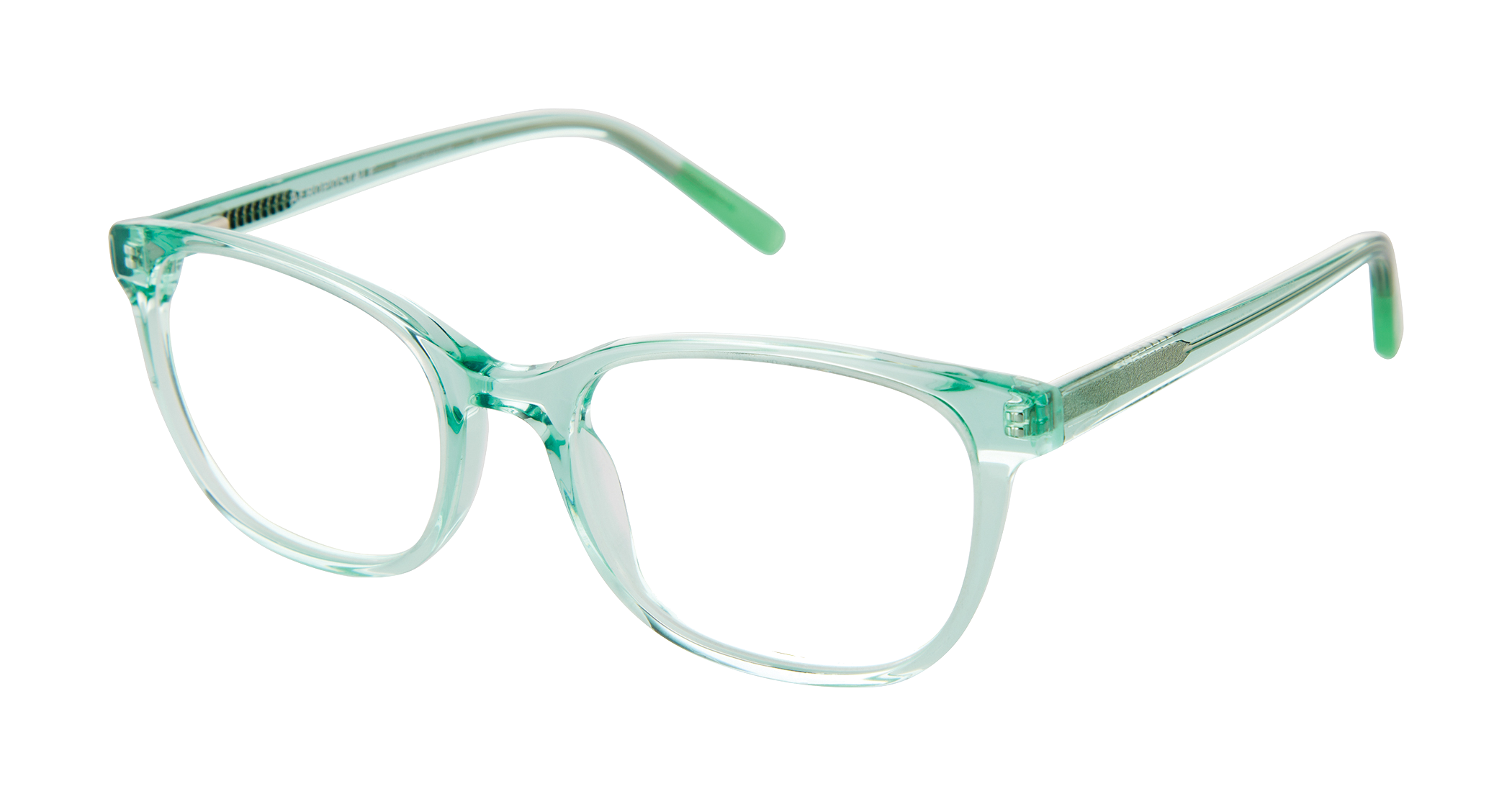
A&A Optical, established in 1971, offers the ultimate selection of premium, quality eyewear to Optometrists, Ophthalmologists and eye care retailers throughout the United States, Mexico, Canada, Latin America, South America, and the Caribbean. Today, fifty years later, A&A Optical markets ten established eyewear collections, including five licensed brands. A&A Optical focuses on lifestyle, fit, quality and attention to detail in each eyewear piece created. From unique, one of a kind looks, European inspired designs to classic value frame styles, A&A Optical is dedicated to delivering the most innovative products and exceptional customer service to meet the growing demands of the optical dispensary and retailer.
Applications Cylindrical lenses Cylindrical lenses can be used in a variety of applications areas. In laser diode collimation, the divergent astigmatic beam of a diode laser can easily be collimated by using a pair of cylindrical lenses placed perpendicular to each other. The lens closer to the laser collimates the fast axis, while the second lens collimates the slow axis of the laser diode. Using two distinct lenses in this way also permits complete removal of the astigmatism inherent in laser diodes.
In practice, the opto-mechanical specification is effectively a process-controlled parameter for the majority of cylindrical optics. When blocking the substrate, care must be taken to reference the cylindrical axis. The same blocks holding the work pieces for milling must also be used when smoothing and polishing, to ensure that the tools are directed parallel to the lens surface, and the smoothing and polishing tools must be parallel and curved to the desired shape.
For quality control of finished components, the use of laser-based interferometers has become common practice. These instruments use coherent optical interference to map the surfaces of components, allowing extremely precise, quantitative measurements. But again, because of the special asymmetry of the cylinder lens, a precise measurement method has to be adapted.
Although cylindrical lenses share some common traits with conventional spherical lenses, the spherical symmetry in the latter makes them easier to describe, manufacture and test. The fabrication and measurement of cylindrical optics poses some unique challenges.
Cylindrical lenses have a spherical radius in one axis only, and so magnify in just one direction. They will transform a point image into a line image, or change the height of an image without altering its width (figure 1).
There are two types of anamorphic lenses on the market for such applications. One compresses the image vertically and the other stretches it horizontally. The second type creates an image that has the same height as the original 16:9 image, but is also 33% wider. Note that such add-on anamorphic lens do not manipulate in any way the image in the complimentary dimension to the one anamorphosed, whether vertically stretched or horizontally squeezed
optics期刊
One of the last operations in the fabrication of spherical lenses is ensuring that the lens is accurately centered with respect to the optical axis. Post-centering of cylindrical surfaces is more complex, because they lack the spherical symmetry and their optical axis is a plane rather than a line.
Surface quality becomes critically important in high-energy laser applications, or where scatter must be reduced in order to improve the signal-to-noise performance. Our method at CVI Melles Griot is to carry out 100% inspection of all surfaces, cleaning and examining them at all four stages of the production process. Our standard cylindrical optics meet a scratch-dig performance of 20-10, and the polishing processes ensure low surface roughness values. On such high-quality surfaces, CVI Melles Griot will deposit ultrahard coatings and guarantee high laser damage thresholds.
We also use interferometry to measure the cylindrical ROC, with either a CGH or a transmission sphere (TS). Figures 5 and 6 show the fringe patterns at the confocal position for these two set-ups.
In either case, once the tool has been determined it is critical to mount the substrate to the tool very carefully otherwise the opto-mechanical specification is at risk.
optical接口
Reveal inner grace and sophistication in eyewear inspired by the woman who adorns herself with rich color and style, whether understated or dramatic. Alexander Collection™ offers fine hand crafted details, such as crystal accents, metal inlays and delicate laser etching in acetate, metal, semi-rimless and combination frame styles.
Surface quality and roughness Two final specifications of interest are the cosmetic surface quality, which describes the level of defects visually detected on the optical surface and the surface roughness. Both of these parameters are the same as for spherical components.
Polishing methods There are two predominant methods of polishing. The first method is the rotary method, where a cylinder rod is rotated about its axis. Barrel blocks with short radius convex cylinders mounted on them are polished in this manner. Concave lenses can also be surfaced this way when mounted on a plate block with a rotating polishing tool.
Theoretically, centering error in the direction perpendicular to the cylindrical axis can be compensated for by edging the lens down. However, correcting the wedge in the parallel direction would require re-surfacing the back plano surface.
Interference patterns During the lens production process, the surface figure can be tested using master test plates and studying the resulting interference fringe patterns to locate errors.
Figure 1 Cylindrical lenses have a spherical radius in one axis only, and so magnify in just one direction. They will transform a point image into a line image, or change the height of an image without altering its width (figure 1). Cylindrical lens surfaces are required in a variety of applications including barcode scanning, holography, optical information processing and computing, laser projection, slit and line detector array illumination, and cinemascope anamorphic lenses. Some of these applications will be discussed later. Figure 2 Although cylindrical lenses share some common traits with conventional spherical lenses, the spherical symmetry in the latter makes them easier to describe, manufacture and test. The fabrication and measurement of cylindrical optics poses some unique challenges. Standard cylindrical lenses are plano-convex or plano-concave in form. They are typically manufactured in a square or rectangular shape and may be edge-ground to a diameter. In either case, two key dimensions describing a cylindrical lens are: perpendicular to the cylindrical axis; and parallel to the cylindrical axis (figure 2). Lens manufacture Cylindrical lenses are typically manufactured from a rectangular convex cylinder. The manner in which the cylinder is mounted or "blocked" for fabrication of a cylindrical lens will be dictated predominantly by the radius of curvature (ROC) and the dimension parallel to the cylindrical axis. There are two main types of cylindrical blocking: Barrel blocking is reserved for short ROC substrates and involves attaching the substrates to a barrel-shaped tool (figure 3). Plate blocking is typically used for long ROC cylinders (figure 4). Figures 3 and 4 In either case, once the tool has been determined it is critical to mount the substrate to the tool very carefully otherwise the opto-mechanical specification is at risk. One of the last operations in the fabrication of spherical lenses is ensuring that the lens is accurately centered with respect to the optical axis. Post-centering of cylindrical surfaces is more complex, because they lack the spherical symmetry and their optical axis is a plane rather than a line. Theoretically, centering error in the direction perpendicular to the cylindrical axis can be compensated for by edging the lens down. However, correcting the wedge in the parallel direction would require re-surfacing the back plano surface. In practice, the opto-mechanical specification is effectively a process-controlled parameter for the majority of cylindrical optics. When blocking the substrate, care must be taken to reference the cylindrical axis. The same blocks holding the work pieces for milling must also be used when smoothing and polishing, to ensure that the tools are directed parallel to the lens surface, and the smoothing and polishing tools must be parallel and curved to the desired shape. Surface shape Two important parameters in defining the surface of a cylindrical lens are the ROC and the surface figure. The ROC can be validated in a similar manner to that used for spherical lenses, although the asymmetry of cylinder lenses means that the spherometers and interferometers used with spherical lenses must be modified. The surface figure represents the deviation of the part from the ideal cylinder shape. In spherical lenses, the surface shape is specified by power and irregularity: power is a measure of how closely the average radius of the part matches the specified radius, and irregularity quantifies the departure of the part from a perfect sphere. For a cylindrical surface, only the power in the direction perpendicular to the cylindrical axis is generally specified. The remaining surface form error, including the unwanted power in the parallel direction, is called the surface figure. It is usually specified in units of wavelengths and quoted separately along the parallel and perpendicular directions. Interference patterns During the lens production process, the surface figure can be tested using master test plates and studying the resulting interference fringe patterns to locate errors. Figure 5 If these test plates are cylindrical, a full map of the cylindrical surface under test can be obtained. If spherical and flat test plates are employed instead, the interference fringes appear over a narrow line profile of the surface. When using a spherical test plate, this profile is oriented along the surface in the direction perpendicular to the cylindrical axis, while employing a flat reference orients the line profile along the parallel direction. If the two surfaces have the same radius and are regular, then the fringes seen are straight and parallel to the contact line, as shown in figure 5. By measuring several profiles in each direction over the surface, any surface irregularity and variation in the radius of curvature can be evaluated. For quality control of finished components, the use of laser-based interferometers has become common practice. These instruments use coherent optical interference to map the surfaces of components, allowing extremely precise, quantitative measurements. But again, because of the special asymmetry of the cylinder lens, a precise measurement method has to be adapted. At CVI Melles Griot, we use computer-generated holograms (CGH) along with a Zygo GPI interferometer to carry out 100% inspection of the final parts. The test plates are also tested interferometrically, which ensures high quality control in the manufacturing process. Figure 6 Using a CGH in transmission in front of the interferometer generates an accurate cylindrical test wavefront that matches the curvature of the surface under test, and thus gives a precise measurement of the surface figure over the entire cylindrical surface. Precision of up to λ/10 PV can be achieved. We also use interferometry to measure the cylindrical ROC, with either a CGH or a transmission sphere (TS). Figures 5 and 6 show the fringe patterns at the confocal position for these two set-ups. Because cylinders are inherently more difficult to fabricate than flat and spherical optics, it has long been difficult to manufacture good interferometric references that would help in manufacturing better cylinders. Obtaining precise, accurate and repeatable metrology is essential for guaranteeing high-quality components. Polishing methods There are two predominant methods of polishing. The first method is the rotary method, where a cylinder rod is rotated about its axis. Barrel blocks with short radius convex cylinders mounted on them are polished in this manner. Concave lenses can also be surfaced this way when mounted on a plate block with a rotating polishing tool. The second method is the Strasbaugh or linear method, working with plate blocks of lenses. This can be seen as a variation of the equivalent process used for making spherical optics, where an axis of the lap is constantly maintained in parallel with the axis of the cylinder surface. Selecting between these two main polishing methods depends on various specifications of the part, such as required surface figure, edge dimensions and the ROC. Both polishing methods correspond to traditional lens fabrication methods and most cylindrical surfaces are still produced by highly skilled technicians using conventional machinery and well-established techniques. There are, however, a number of alternative methods being developed that integrate computer technology with radically different polishing methods. These include computer-controlled polishing or magnetorheological finishing techniques. Such techniques allow improved product performance, especially with regard to the surface figure of the lens, but they are generally too expensive for most applications. Surface quality and roughness Two final specifications of interest are the cosmetic surface quality, which describes the level of defects visually detected on the optical surface and the surface roughness. Both of these parameters are the same as for spherical components. Surface quality becomes critically important in high-energy laser applications, or where scatter must be reduced in order to improve the signal-to-noise performance. Our method at CVI Melles Griot is to carry out 100% inspection of all surfaces, cleaning and examining them at all four stages of the production process. Our standard cylindrical optics meet a scratch-dig performance of 20-10, and the polishing processes ensure low surface roughness values. On such high-quality surfaces, CVI Melles Griot will deposit ultrahard coatings and guarantee high laser damage thresholds. Applications Cylindrical lenses Cylindrical lenses can be used in a variety of applications areas. In laser diode collimation, the divergent astigmatic beam of a diode laser can easily be collimated by using a pair of cylindrical lenses placed perpendicular to each other. The lens closer to the laser collimates the fast axis, while the second lens collimates the slow axis of the laser diode. Using two distinct lenses in this way also permits complete removal of the astigmatism inherent in laser diodes. Another growing market is anamorphic lenses, first developed in the film industry, which deliberately distort an image to allow standard 35 mm films to record images in widescreen format. One new application is the use of an anamorphic lens to enable 16:9 aspect ratio digital projectors to create full-screen 2.35:1 (Cinemascope) images, for display on super-wide format home-theatre screens. In a 16:9 screen format the image width is 1.78× its height. So when a 16:9 projector with a conventional lens projects 2.35:1 images, these images have to be squeezed down to fit into the smaller 16:9 frame, leaving black bars above and below the image. This diminishes both the projector's ultimate performance (in resolution and brightness) and the true immersive experience this 2.35:1 format represents. The solution is to first electronically stretch the image in the vertical direction, so as to use all of the pixels from the 16:9 projector. If this was displayed with a normal lens, the image would fill a full 16:9 screen, but would look vertically stretched. In effect, figures would look excessively tall and skinny. By affixing an anamorphic lens to the projector in front of its standard lens, the image is returned to its original aspect ratio and appears optically undistorted, while also achieving higher resolution and brightness. There are two types of anamorphic lenses on the market for such applications. One compresses the image vertically and the other stretches it horizontally. The second type creates an image that has the same height as the original 16:9 image, but is also 33% wider. Note that such add-on anamorphic lens do not manipulate in any way the image in the complimentary dimension to the one anamorphosed, whether vertically stretched or horizontally squeezed It should also be noted that although using cylindrical lenses or prisms are the two main approaches used to anamorphose an image, some alternative approaches using hybrid cylindrical/prism designs have also been developed. A third application area is in light sheets, used in several optical measurement techniques, such as particle image velocimetry, planar laser-induced fluorescence and flow visualization studies. Manufacturing of cylindrical lenses is not a simple task. Only a few manufacturers, with the best control equipment, can measure and guarantee the quality of cylindrical optics. It is therefore highly recommended that you check with your supplier to ensure that the quality control tools meet your requirements. At CVI Melles Griot, we pride ourselves in the largest range of high-precision cylindrical lenses on the market. • This article originally appeared in the December 2008 issue of Optics & Laser Europe magazine. View pdf of article
Standard cylindrical lenses are plano-convex or plano-concave in form. They are typically manufactured in a square or rectangular shape and may be edge-ground to a diameter. In either case, two key dimensions describing a cylindrical lens are: perpendicular to the cylindrical axis; and parallel to the cylindrical axis (figure 2).
Because cylinders are inherently more difficult to fabricate than flat and spherical optics, it has long been difficult to manufacture good interferometric references that would help in manufacturing better cylinders. Obtaining precise, accurate and repeatable metrology is essential for guaranteeing high-quality components.
optical中文
A third application area is in light sheets, used in several optical measurement techniques, such as particle image velocimetry, planar laser-induced fluorescence and flow visualization studies.
A&A Optical is where top Optometrists, Ophthalmologists and eye care retailers find the best-selling prescription eyewear and premium frames, at a fraction of the cost. Grow your eyecare practice with increased optical dispensary sales, higher profit margins, and no minimums. Welcome to the ultimate eyewear buying experience.
Surface shape Two important parameters in defining the surface of a cylindrical lens are the ROC and the surface figure. The ROC can be validated in a similar manner to that used for spherical lenses, although the asymmetry of cylinder lenses means that the spherometers and interferometers used with spherical lenses must be modified.
Optics
There are, however, a number of alternative methods being developed that integrate computer technology with radically different polishing methods. These include computer-controlled polishing or magnetorheological finishing techniques. Such techniques allow improved product performance, especially with regard to the surface figure of the lens, but they are generally too expensive for most applications.
It should also be noted that although using cylindrical lenses or prisms are the two main approaches used to anamorphose an image, some alternative approaches using hybrid cylindrical/prism designs have also been developed.
Cylindrical lens surfaces are required in a variety of applications including barcode scanning, holography, optical information processing and computing, laser projection, slit and line detector array illumination, and cinemascope anamorphic lenses. Some of these applications will be discussed later.
The surface figure represents the deviation of the part from the ideal cylinder shape. In spherical lenses, the surface shape is specified by power and irregularity: power is a measure of how closely the average radius of the part matches the specified radius, and irregularity quantifies the departure of the part from a perfect sphere.
The optics of cylindrical lenses allow their use in applications for which spherical lenses are not suited. CVI Melles Griot has developed the technology for use in several markets.
One new application is the use of an anamorphic lens to enable 16:9 aspect ratio digital projectors to create full-screen 2.35:1 (Cinemascope) images, for display on super-wide format home-theatre screens.
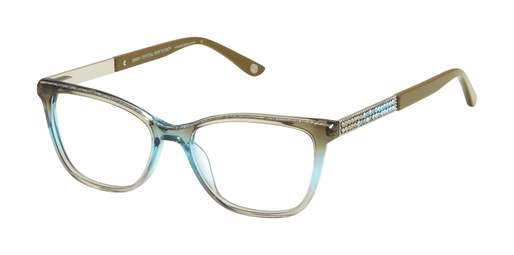
Jimmy Crystal New York™ is synonymous with dramatic, alluring, and captivating design. Each frame is unique and special, all hand set with crystals, in the heart of NYC’s Fashion District. With iconic eye shapes and shimmering stone patterns, there is a style for every taste, every occasion and every day.


 Ms.Cici
 8618319014500