
Ring Lights - ring loghts
Bei herkömmlichen Bildverarbeitungssystemen sind Haarkratzer und Flecken auf einer glänzenden Metalloberfläche möglicherweise nur unter bestimmten Beleuchtungsbedingungen sichtbar. Unter diesen Bedingungen wird das Lesen von Zeichen und Barcodes oft zu einer außerordentlichen Herausforderung. Die Lösung in solchen Situationen ist der KEYENCE LumiTrax™-Spiegelreflexionsmodus. Die Kombination aus fortschrittlicher Hardware und ausgereiften Algorithmen ermöglicht es kontrastärmste Merkmale und kleinste Defekte prozesssicher mit Hilfe der Zeilenabtastung zu extrahieren.
One of the primary and favorite techniques used in all forms of optical microscopy for the past three centuries, brightfield illumination relies upon changes in light absorption, refractive index, or color for generating contrast. As light passes through the specimen, regions that alter the direction, speed, and/or spectrum of the wavefronts generate optical disparities (contrast) when the rays are gathered and focused by the objective. Resolution in a brightfield system depends on both the objective and condenser numerical apertures, and an immersion medium is required on both sides of the specimen (for numerical aperture combinations exceeding a value of 2.3). Digital cameras provide the wide dynamic range and spatial resolution required to capture the information present in a brightfield image. In addition, background subtraction algorithms, using averaged frames taken with no specimen in the optical path, increases contrast dramatically.
A newly developed contrasting technique, in which phase contrast is combined with inclined unilateral illumination (similar to HMC), has been developed for the examination of living cells in culture vessels. An additional stop shaped like a ring sector is used on the illumination side, permitting unilateral inclined illumination. Three illumination modes, unilateral darkfield, VAREL (variable relief) contrast, and inclined brightfield (similar to oblique illumination or HMC) are set by shifting the stop in the radial direction from the outside to the inside (see Figure 7) and a segment of a matching annulus is moved into position. This slit directs the source illumination to pass through a second ring of high absorption on the objective aperture's periphery, which suppresses its intensity by an amount dependent upon the density of the outer ring. The diffracted orders of light pass through the objective without being suppressed by the VAREL ring. You can also manipulate the position of the slit if you want to vary the extent the source illumination is suppressed.
Bevor die Bilder analysiert werden, werden durch Vorverarbeitung unerwünschte/verrauschte Eigenschaften entfernt und gleichzeitig gewünschte Merkmale in den Bilddaten hervorgehoben.
In der Lebensmittel- und Medizinindustrie Produktsicherheit zu gewährleisten gelten immer höhere Inspektionsstandards und Anforderungen and die Rückverfolgbarkeit. Ein Bildverarbeitungssystem ermöglicht es, Inspektionen zu automatisieren und Bild-/Ergebnisdaten einfach zu speichern. Anwendungsbeispiele sind:
Matrixkameras werden in vier Hauptgruppen eingeteilt: hochauflösende Kameras, Hochgeschwindigkeits-Kameras, Standard-Kameras und Minikameras. Zusätzlich gibt es noch die Option Farbe oder Schwarz/Weiß. Die Auswahl der richtigen Kamera ist abhängig von der Anwendung, was im Folgenden skizziert wird.
Die Bildverarbeitungssysteme von KEYENCE wurden mit Blick auf die Bedürfnisse der Benutzer entwickelt und bieten eine einfache Bedienung mit intuitiver Benutzeroberfläche. In dieser Broschüre finden Sie Beispiele für leistungsstarke Hilfsprogramme, wie z. B. konfigurierbare Bedienbildschirme und die Kamerainstallationsreplikation, sowie einen umfangreichen Werkzeugkatalog.
- Anwesenheitserkennung: Sicherstellung einer korrekten Kistenzählung, mehrere Komponenten wie z. B. Strohhalme, die an Getränkekartons haften - Prüfung von Qualitätsmerkmalen: Zeichenerkennung (OCR) für Chargencodes, korrekte Form und keine Defekte bei Lebensmittelschalen, Schrumpffolien, Blisterverpackungen und Dosen - Mess-/Ausrichtungskontrollen: Etikettenplatzierung, Siegelbreite und -position, Nadelabmessungen, Erfassen von Positionsdaten für Pick-and-Place-Roboteranwendungen
In order for the beams to interfere, the vibrations of the beams of different path length must be brought into the same plane and axis. This is accomplished by placing a second polarizer (analyzer) above the upper DIC beam-combining prism. The light then proceeds toward the eyepiece where it can be observed as differences in intensity and color. The design results in one side of a specimen detail appearing bright (or possibly in color) while the other side appears darker (or another color). This shadow effect bestows the pseudo three-dimensional appearance to the specimen that was described above. There are numerous advantages in DIC microscopy as compared to phase contrast microscopy. With DIC, it is possible to make fuller use of the numerical aperture of the system and to provide optical staining (color). DIC also allows the microscope to achieve excellent resolution. Use of full objective aperture enables the microscopist to focus on a thin plane section of a thick specimen without confusing images from above or below the plane. Annoying halos, often encountered in phase contrast, are absent in DIC images, and suitable achromat and fluorite objectives can be used for this work. It is important to keep in mind, however, since DIC is based on polarized light principles, highly birefringent specimens or those embedded in birefringent materials should not be observed under DIC.
- Anwesenheitserkennung: Kunststoffbeschichtungen, Vorhandensein von Kappen, korrekte Etikettierung - Prüfung von Qualitätsmerkmalen: Inspektion der Innenfläche von Behältern, Produktgrat, Kratzer/Abplatzungen im Kunststoff, Fremdkörper, Stiftlöcher - Mess-/Ausrichtungskontrollen: Erkennung einer Außermittigkeit von Dichtungen, Erkennung von Etikettenversatz, Abmessungen von Flaschenöffnungen
Die Modellreihe CV-X ist ein innovatives, benutzerfreundliches Bildverarbeitungssystem, das mit Hochgeschwindigkeitskameras Inspektionsaufgaben in allen Fertigungsindustrien löst. Das Bildverarbeitungssystem CV-X umfasst Kameras und Beleuchtung, um Teile in der Fertigungslinie stabil abzubilden und so die Effizienz zu steigern und die Qualität zu sichern. Zu den belieferten Branchen gehören die Automobil-, Elektronik-, Medizin-, Lebensmittel- und Verpackungsindustrie sowie alle Prozesse, die eine Inspektion von Teilen mit hohen Stückzahlen erfordern. Zu den üblichen Anwendungen gehören die Fehlererkennung und Oberflächeninspektion, die Prüfung auf das Vorhandensein von Teilen und Merkmalen, die Überprüfung von Baugruppen, Messungen und das Lesen von Codes.
Buy best portable full HD LED projectors online at best prices. Choose from our widest range of projectors from top brands like IBS, Egate, Play, ...
In phase contrast microscope configuration, the condenser aperture diaphragm is replaced by a phase stop (the size of which depends upon objective and condenser numerical aperture) that illuminates the specimen via the condenser optical components in a hollow cone of light fashion, as illustrated in Figure 3(a). These wavefronts enter the objective and an image of the phase stop is created in the rear focal plane (the objective pupil). Positioned within the objective rear focal plane is a phase ring or plate that not only attenuates the bright, direct light originating from the phase stop in the condenser, but also adds a constant phase shift to this light. If the specimen contains sub-structures that have mixed refractive indices, these entities guide the light from the direct waves into new paths (red dotted line in Figure 3(a)). Wavefronts diffracted by the specimen (in effect, those containing structural information) will not pass through the phase ring in the objective, meaning that they will not be attenuated or retarded. All of the wavefronts are ultimately recombined to form the intermediate image by the tube lens.
Recently, a renewed interest in transmitted darkfield microscopy has arisen due to its advantages when used in combination with fluorescence microscopy. Darkfield microscopy is a specialized illumination technique that capitalizes on oblique illumination, as described above, to enhance contrast in specimens that are not imaged well under normal brightfield illumination conditions. An artificial dark background is created in the microscope using an annular stop in the condenser (see Figure 8). Although the condenser optics then illuminate the sample, they do so with a hollow inverted cone of light that passes through the specimen at extremely oblique angles at all azimuths so that only the light interacting with specimen features is able to enter the microscope objective to form a bright image of the specimen superimposed onto a dark background. To create the high angles, it is necessary for the objective aperture to be smaller than the inner aperture of the illuminating light cone (see Figure 8(a)). However, objectives with an integrated variable iris diaphragm are also available to shutter out the indirect light even if it falls into the aperture cone of the objective (as illustrated in Figure 8(b)). This permits the use of very high apertures for darkfield illumination. Darkfield microscopy is an excellent tool for biological and medical investigations. It can be effectively used at high magnifications to image living bacteria, or at low magnifications to view and image cells, tissues, and whole mounts.
Die Verwendung eines Bildverarbeitungssystems als "Augen" eines Industrieroboters kann die Genauigkeit und Effizienz fortschrittlicher Kommissionierungsvorgänge erheblich verbessern. Das Bildverarbeitungssystem berechnet die Position eines Produkts im Koordinatensystem des Roboters und gibt diese Messungen direkt an die Robotersteuerung zur dynamischen Anpassung aus.
Bildverarbeitungssysteme werden an die Anforderungen der jeweiligen Anwendung angepasst. Jedes System besteht in der Regel aus einer Kamera, einer Beleuchtung und einem Controller. Im Gegensatz zu Smart Kameras benötigen Sie keinen zusätzlichen Aufwand um mehrere Beleuchtungen und Kameras zu synchronisieren. In diesem Abschnitt sind die Prinzipien der Verwendung eines Bildverarbeitungssystems für Inspektionen vorgestellt und der Prozess vom Beginn der Bildaufnahme bis zur Ausgabe der Inspektionsergebnisse erklärt.
Gewöhnlich wird eine farbige Beleuchtung mit einer S/W-Kamera gepaart und die Farbe (Wellenlänge) des Lichts variiert je nach gewünschter Inspektion. Farben, die der eines bestimmten Prüfobjekts nahe kommen oder komplementär zur Farbe des Prüfobjekts sind, können das Bild strategisch manipulieren und stabilisieren. Um feine Unterschiede in der Oberflächenbeschaffenheit zu erfassen und die Inspektionen weiter zu stabilisieren, verwendet die intelligente, multispektrale Beleuchtungstechnologie acht verschiedene Lichtfarben, um mehr Daten pro Pixel zu erfassen. Durch die Daten mehrerer Wellenlängen wird ein größerer Kontrast zwischen gleichartigen Farben erzeugt, und es kann trotz der Verwendung einer S/W-Kamera ein Echtfarbbild auf dem Bedienbildschirm angezeigt werden.
Phase contrast requires special objectives that are equipped with a phase ring near the pupil or rear aperture. They are easy to recognize by the green inscription that denotes the size of the corresponding condenser phase stop: Ph1, Ph2, or Ph3. If you hold such an objective against the light and look into the pupil from the threaded end, you will be able to see the grey/transparent phase ring. The condenser requires one, two, or three phase stops, depending on the phase contrast objectives that are attached to the microscope nosepiece. The required ring diameter increases with the numerical aperture (high apertures require the maximum diameter (Ph3), for example 0.9 in air or 1.3 with oil immersion). Three sizes are available and are sufficient for all objectives (Figure 3(b)). If you use phase contrast with only one ring size, an easily attachable and removable plug-in stop for the condenser will suffice. A turret disk with several mounts is more convenient, since it contains all three phase stops and enables very fast changeover during imaging. Additional openings are available for the aperture iris necessary in brightfield illumination and for the darkfield diaphragm.
Differential interference contrast microscopy
Bracket App is a simple way to create single and double elimination tournament brackets ... Open the Mac App Store to buy and download apps. Bracket App 4+. Let's ...
Die Beleuchtungsrichtung, -farbe und -art wird durch eine Kombination aus Prüfobjektmerkmalen, Inspektionsanforderungen und der Umgebung bestimmt. Im Folgenden wird eine allgemeine Vorgehensweise zur Auswahl der Beleuchtung beschrieben:
The image of a specimen in phase contrast can be influenced by appropriately selecting the retardation of the direct (non-diffracted) beam through careful selection of the phase ring in the objective. Depending on the retardation value selected, objects with a higher refractive index than their surroundings appear either brighter or darker than their surroundings. This is also called either positive or negative phase contrast. In modern microscopes, positive phase contrast is standard, where the darkness of object features increases with their refractive index. The effect simulates absorption to the observer's eye in areas where a higher refractive index produces high contrast features. This impression is considered the optimum, particularly with cells and tissue in aqueous media because cell nuclei and organelles, for example, appear darker than the cytoplasm. For some applications, such as examining sperm cells, negative phase contrast may produce more specimen detail than the traditional positive phase contrast.
Die Modellreihe XG-8000 ist ein Hochleistungs-Bildverarbeitungssystem für Maschinenbauer und Integratoren. Die Stärken der Plattform sind die hohe Anpassungsfähigkeit und Flexibilität durch den modularen Aufbau, aber auch die leistungsstarken Bildverarbeitungsalgorithmen und Bildaufnahmetechnologien. Die Modellreihe unterstützt Matrixkameras bis zu 21 Megapixel, Zeilenkameras und sogar 3D-Kameras. Für jede Anwendung lässt sich so ein passendes Bildverarbeitungssystem für den industriellen Einsatz konfigurieren. Die Modellreihe XG-8000 verfügt außerdem über die LumiTrax™-Funktion (Shape from Shading) – eine neuartige Bilderfassungsmethode, die die Kamera, die Beleuchtung und die Prüfalgorithmen synchronisiert – und den hochstabilen Suchalgorithmus ShapeTrax™ 2 für hervorragende Stabilität und Reaktionsfähigkeit bei allen Prüfobjekten und Inspektionsbedingungen.
(1) Bestimmen Sie die Brennweite anhand des Sichtfeldes (FOV) und der Anforderungen an den Arbeitsabstand (WD). (2) Bestimmen Sie die erforderliche Tiefenschärfe anhand der Höhe und Form des Prüfobjekts. Prüfobjekte mit unterschiedlich hohen Oberflächen und Merkmalen erfordern eine größere Tiefenschärfe. Die Tiefenschärfe nimmt mit zunehmendem Arbeitsabstand, mit abnehmender Brennweite und mit kleiner werdender Blende zu. (3) Wählen Sie ein hochauflösendes Objektiv oder ein Standardobjektiv entsprechend der erforderlichen Prüfgenauigkeit und dem Kontrast des Prüfobjekts.
Dark field microscopy
... Table 1). Wavelength, Color, Designation, Element. 365.0146 nm, ultraviolet, i ... Table 1: Table of spectral lines which are frequently used in optics. See ...
Bei konventionellen Industrierobotern müssen die Anwender die Koordinaten manuell mit einem Programmierhandgerät festlegen. Dieser manuelle Vorgang ist zeitaufwendig und die Genauigkeit variiert von Anwender zu Anwender. KEYENCE Bildverarbeitungssysteme können direkt mit Robotern vieler Hersteller kommunizieren, was eine einfache Verbindung und effiziente Programmierung des Roboters ermöglicht. Durch diese Verbindung werden die aufwändigen Aufgaben der Kalibrierung und Berechnung automatisiert, was die Prüfungen stabilisiert und den Zeitaufwand für die Integration reduziert.
The appropriate arrangement for polarized light imaging is relatively easy to implement on virtually any microscope. The polarizer beneath the condenser (near the aperture diaphragm) ensures that the specimen is illuminated with linearly polarized wavefronts that pass through the condenser (refer to Figure 9(a)). The analyzer (a second polarizer), which is oriented with the azimuth arranged at an angle of 90 degrees to that of the polarizer, is located behind the objective. The tube lens forms the intermediate image, which is projected through the eyepieces or onto a camera imaging plane. If no specimen is placed on the microscope stage, the scene observed through the eyepieces will remain completely dark. When illuminated, many specimens turn the vibration direction of the polarized light out of the plane produced by the polarizer. Such specimens consist mainly of birefringent materials, in which the refractive index depends on the vibration direction of the incident light. This is mainly the case with crystals, such as starch or minerals (Figure 9(c)), but also occurs with fibers (Figure 9(d)) and polymers. If such materials are viewed under the polarization microscope between the crossed polarizer and the analyzer, bright areas can be seen in the image because light is partially transmitted by the analyzer.
Polarized light microscopy (Figure 1(f)) is conducted by viewing the specimen between crossed polarizing elements inserted into the optical train before the condenser and after the objective. Assemblies within the cell having birefringent properties, such as the plant cell wall, starch granules, and the mitotic spindle, as well as muscle tissue, rotate the plane of light polarization, appearing bright on a dark background. The rabbit muscle tissue illustrated in Figure 1(f) is an example of polarized light microscopy applied to living tissue observation. Note that this technique is limited by the occurrence of birefringence in living cells and tissues, and has yet to be fully explored. As mentioned above, differential interference contrast operates by placing a matched pair of opposing Nomarski prisms between crossed polarizers, so that any microscope equipped for DIC observation can also be employed to examine specimens in plane-polarized light simply by removing the prisms from the optical pathway.
The methodology surrounding darkfield microscopy, although widely used for imaging transparent specimens throughout the 19th and 20th Centuries, is limited in use to physically isolated cells and organisms (as presented in Figure 1(e)). In this technique, the condenser directs a cone of light onto the specimen at high azimuths so that first-order wavefronts do not directly enter the objective front lens element. Light passing through the specimen is diffracted, reflected, and/or refracted by optical discontinuities (such as the cell membrane, nucleus, and internal organelles) enabling these faint rays to enter the objective. The specimen can then be visualized as a bright object on an otherwise black background. Unfortunately, light scattered by objects removed from the focal plane also contribute to the image, thus reducing contrast and obscuring specimen detail. This artifact is compounded by the fact that dust and debris in the imaging chamber also contribute significantly to the resulting image. Furthermore, thin adherent cells often suffer from very faint signal, whereas thick plant and animal tissues redirect too much light into the objective path, reducing the effectiveness of the technique.
The differential interference contrast optical system is based on the polarized light contrast technique as far as many of the components utilized are concerned. DIC for a modern transmitted light microscope is different than that in reflected light because two birefringent prisms are used (see Figure 6), and the specimen's optical path difference is determined by the product of the refractive index difference (between the specimen and its surrounding medium) and the thickness (geometrical distance) traversed by a light beam between two points on the optical path (Figure 5). Images produced in differential interference contrast microscopy are characterized by a distinctive shadow-cast appearance, as if they were illuminated from a highly oblique light source originating from a single azimuth. Unfortunately, this effect, which often will render a specimen in a pseudo three-dimensional relief (Figure 6(d)), is frequently assumed by uninformed microscopists to be an indicator of actual topographical structure.
Künstliche Intelligenz und regelbasierte Systeme haben beide jeweils für sich Vor- und Nachteile. Die Modellreihe VS bietet sowohl AI- als auch regelbasierte Algorithmen, sodass je nach Situation die passende Prüffunktion ausgewählt werden kann. Das Ergebnis sind schnelle und stabile Problemlösungen.
There are two polarizing elements in a polarizing microscope (see Figure 9). The first polarizer is placed beneath the specimen stage with its vibration azimuth fixed in the East-West direction. Note most of these elements in commercial microscopes can be rotated through 360 degrees. Another polarized (the analyzer), which is usually aligned with a vibration direction oriented North-South (but again rotatable on some microscopes), is placed above the objective and can be moved into and out of the light path as needed. When both the polarizer and analyzer are inserted into the optical path, their vibration azimuths are positioned at right angles to each other. In this configuration, the polarizer and analyzer are crossed, with no light passing through the optical system and a dark background present in the eyepieces (Figure 9(a)). Linearly polarized light waves are generated by polarizers that filter out a privileged plane from the statistical confusion of vibrational directions prevailing in natural light. The two orthogonal components of light (ordinary and extraordinary waves) travel at different speeds through the specimen and, as a result, observe different refractive indices, a phenomenon known as birefringence (derived from the terms double or bi refraction). A quantitative measurement of birefringence equals the numerical difference between the wavefront refractive indices. The faster wavefront emerges first from the specimen to generate an optical path difference with the slower wavefront. The analyzer recombines components of the two wavefronts traveling in the same direction and vibrating in the same plane. This polarizing element ensures that the two wavefronts have the same amplitude at the time of recombination for maximum contrast.
Automatische Berechnung der optimalen Roboterbahn inkl. Greifer. Dadurch kann der Zeitaufwand für die Erstellung von Roboterprogrammen erheblich reduziert und gleichzeitig ein stabiler Betrieb gewährleistet werden.
Eine Farbkamera wird im Allgemeinen bevorzugt, wenn auf Farbveränderungen oder farbliche Unregelmäßigkeiten geprüft werden soll. Jedes Pixel eines Farbbildes enthält RGB-Informationen, die dreimal so groß sind wie die Daten eines monochromen Pixels. Da es mehr Daten pro Pixel gibt, ist die Extraktion und Differenzierung einfacher. Monochrome Kameras werden bevorzugt für messtechnische Prüfungen eingesetzt, bei denen eine starke Kantenextraktion erforderlich ist. S/W-Kameras werden häufig auch mit farbiger Beleuchtung kombiniert, um die Inspektion zu erleichtern. Beispiele sind die Abschwächung des Umgebungslichts, das Fluoreszieren eines UV-gefärbten Materials und die Hervorhebung von Oberflächenkratzern.
Verarbeitete Bilddaten werden verwendet, um eine OK/NG-Beurteilung durchzuführen, Messergebnisse aufzuzeichnen oder Teile zu kategorisieren. Anschließend können Bilder und Daten ausgegeben sowie die Kommunikation mit anderen Geräten hergestellt werden.
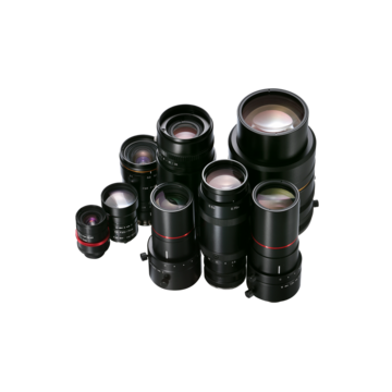
Die Produktpalette der Objektive von KEYENCE bietet die nötige Flexibilität, um alle Installations- und Anwendungsanforderungen industrieller Bildverarbeitungskameras zu erfüllen. Wählen Sie aus Merkmalen wie hoher Auflösung, geringer Verzerrung, IP-Schutzklasse, telezentrischer Abbildung oder platzsparender Bauform das beste Objektiv, um den Bildverarbeitungssystemen optimale Rohbilder zur Verfügung zu stellen. Auch Zubehör wie Polarisations-, Kanten- und Blaufilter zur Unterstützung einer stabilen Bilderfassung durch Reduzierung von Umgebungseinflüssen gehört zum Sortiment. Schutzfilter sorgen für eine lange Lebensdauer des Objektivs, indem sie Schäden durch Verschmutzung und Wartung verhindern.
30 products · GlowPRO 2 Ring Light · GlowPRO 2 Ring Light · GlowArc Artisan Light · GlowArc Artisan Light · GlowPRO 3 Ring Light · GlowPRO 3 Ring Light.
Differential interference contrast microscopy (DIC; Figure 1(c)) requires plane-polarized light and additional light-shearing (Nomarski) prisms to exaggerate minute differences in specimen thickness gradients and refractive index. Lipid bilayers, for example, produce excellent contrast in DIC because of the difference in refractive index between aqueous and lipid phases of the cell. In addition, cell boundaries in relatively flat adherent mammalian and plant cells, including the plasma membrane, nucleus, vacuoles, mitochondria, and stress fibers, which usually generate significant gradients, are readily imaged with DIC. In plant tissues, the birefringent cell wall reduces contrast in DIC to a limited degree, but a properly aligned system should permit visualization of nuclear and vacuolar membranes, some mitochondria, chloroplasts, and condensed chromosomes in epidermal cells. Differential interference contrast is an important technique for imaging thick plant and animal tissues because, in addition to the increased contrast, DIC exhibits decreased depth of field at wide apertures, creating a thin optical section of the thick specimen. This effect is also advantageous for imaging adherent cells to minimize blur arising from floating debris in the culture medium.
The wavefronts that have all been retarded to varying degrees by details in the specimen are superimposed in the intermediate image over the shifted and attenuated wavefronts where they amplify or attenuate each other (depending on the phase), forming the final phase contrast image observed in the eyepieces. These interference processes in the intermediate image create bright and dark areas of the various structures having refractive index (and/or thickness) variations in the specimen. Optimum contrast is created by selecting the correct retardation and attenuation values, which is a function of the optical properties of the phase ring in the objective aperture.
The phase stops must be centered after they have been installed in the condenser so that the image of the phase stop in the objective pupil corresponds exactly with the position of the phase ring in the beam path (see Figure 4(c)). Centering is performed using two small wrenches (or screwdrivers, depending upon the microscope model) on the turret disk of the condenser. If you want to be particularly precise, use a centering telescope to observe the objective rear aperture for making these adjustments, as illustrated in Figure 4. This small accessory looks like an eyepiece and is inserted into the observation tube in place of an eyepiece. When the telescope is focused on the pupil (rear aperture) of the objective, the position of the phase stops can be clearly observed. Again, look into the objective pupil and bring the bright image of the condenser phase stop into coincidence with the phase ring of the objective. This is clearly shown in Figure 4. In Figures 4(a) and 4(b), the phase stop is not aligned with the objective phase plate, while the stop and phase plate are in perfect congruence in Figure 4(c).
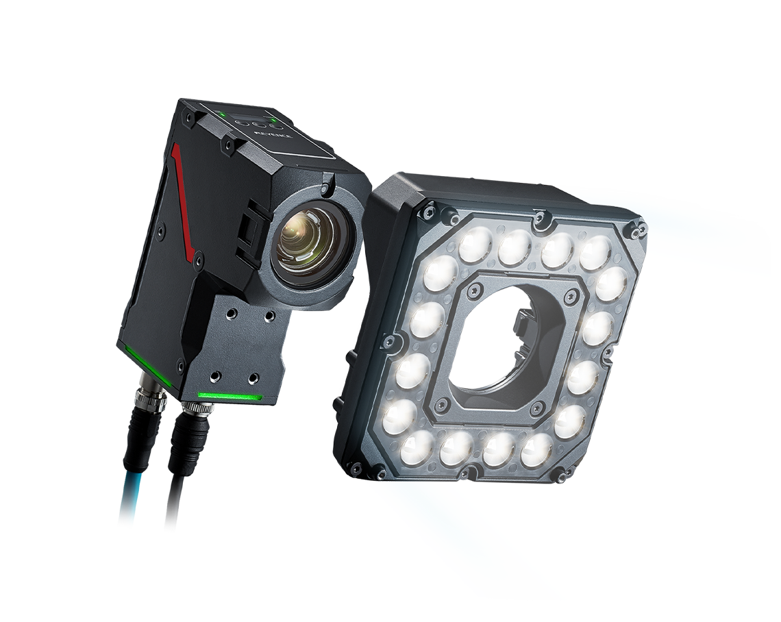
KEYENCE LED-Beleuchtungen können direkt an KEYENCE-Bildverarbeitungssysteme angeschlossen und von diesen gesteuert werden. So wird die gewünschte Beleuchtungssituation schnell erreicht, egal ob es um eine möglichst gleichmäßige Ausleuchtung des Prüfobjekts oder das hervoreben bestimmter Merkmale geht. Die Produktpalette reicht von bewährter Bildverarbeitungsbeleuchtung (erhältlich in Weiß, Rot und Blau) bis hin zu innovativen, leistungsstarken Beleuchtungstechniken. Die leistungsstarke Beleuchtung ermöglicht Überprüfungen, die zuvor unmöglich oder unzuverlässig waren. Die LumiTrax™-Beleuchtung ermöglicht eine Qualitätsprüfung von Oberflächen ohne Beeinflussung durch Hintergrundblendung und Muster. Die multispektrale Beleuchtung kombiniert 8 verschiedene Lichtfarben, um subtile Unterschiede und Defekte zu unterscheiden. Die Streifenprojektionsbeleuchtung ermöglicht in Kombination mit einer 2D-Kamera ein Bildverarbeitungssystem, das simultane 2D- und 3D-Bilder aufnehmen und auswerten kann.
2024114 — FOV. The field of view observes your optical device that captures the scene's width. In FOV, your action camera covers the maximum area by ...
Neben der Identifizierung von Teilen, der Erkennung von Fehlern und der Überprüfung können Bildverarbeitungssysteme auch für den wachsenden Bedarf an bildverarbeitungsgesteuerter Robotik eingesetzt werden. Die Bildverarbeitungssysteme von KEYENCE sind so konzipiert, dass sie direkt an alle gängigen Marken von Robotersteuerungen angeschlossen werden können. Durch mitgelieferte Roboterprogramme für jeden Hersteller entfällt für den Endanwender die komplizierte Roboterprogrammierung. Zu den unterstützten Marken gehören FANUC, Yaskawa, ABB, KUKA, Denso, Epson, Kawasaki, Mitsubishi, Staubli, Yamaha, Universal Robots und andere.
Bright field microscopy advantages and disadvantages
Wir bei KEYENCE entwickeln ständig fortschrittliche, firmeneigene Bildverarbeitungstechnologien. Unser Sortiment umfasst eine breite Palette von Produkten, die es uns ermöglichen, Lösungen für die zahlreichen Herausforderungen zu finden, die tagtäglich in Produktionsstätten auftreten. Zu diesen Produkten gehören sowohl intelligente All-In-One-Modelle als auch Steuergeräte mit hoher Geschwindigkeit für Matrix-, Zeilen- und 3D-Kameras. Je nach Situation wählen Sie, ob Sie AI-, regelbasierte- oder eine Kombination dieser Prüffunktionen einsetzen möchten. KEYENCE liefert den gesamten Umfang, der für Bildverarbeitungssysteme benötigt wird, einschließlich Objektive und Filter. Dies runden wir mit unserem Portfolio an Standard- sowie intelligenten Spezialbeleuchtungen ab.
Die stabile Erkennung von Graten und Spänen hängt von der Genauigkeit der Kantenextraktion ab. Die Bildverarbeitungssysteme von KEYENCE umfassen Kantendefektwerkzeuge, die Linien, Kreise, Ovale und freie Kantenformen präzise extrahieren, um alle Abschnitte zu erkennen, die zu weit von der erwarteten Form abweichen. Der Benutzer kann Schwellenwerte festlegen, um die Größe und den Schweregrad der berücksichtigten Fehler zu steuern.
Um ein Bild zu erfassen, wird ein Bauteil beleuchtet, welches dann durch ein Objektiv auf den Bildsensor der Kamera abgebildet wird. Die gesammelten Bildinformationen aus dieser Erfassung werden dann zur Bildverarbeitung und -beurteilung an den Controller übertragen.
MTF-1 inhibitor APTO-253 inhibits MTF-1 activity and thereby induces the ... Search NCI's Drug Dictionary. Starts with. Contains. Please enter up to 30 ...
Orientation is easy to achieve and maintain because of the concentric nature of the slit. Furthermore, because of the VAREL ring's location in the objective, VAREL and phase contrast rings can be combined in the same objective. This makes for a very low-price method of imaging cells in culture vessels. The problems of imaging in both traditional and routine tissue culture applications can be resolved with this method, it is a successful option for the examination of living objects (micromanipulation), and a range of structures with varying optical thickness are easily imaged with VAREL. Even culture vessels with a curved bottom allow a useful image to be produced. Phase contrast alone sometimes fails in such cases because a curved chamber base acts like a lens and impairs the superimposition of phase rings. A slider contains two of the mentioned sectors to allow illumination to be performed from the left or right, as required. This makes it possible to contrast cells even near the edges of the holes in microtiter plates.
- Anwesenheitserkennung: Pins, Steckverbinder, Lot - Prüfung von Qualitätsmerkmalen: Kristalloszillatoren, IC-Formen, LEDs - Mess-/Ausrichtungskontrollen: Pin-Kontrolle & Koplanarität, Träger-Ausrichtung, Leiterplattenverzug, Klemmenhöhen
Bildverarbeitungssysteme kombinieren Industriekameras, Objektive und Beleuchtungen, um die visuelle Prüfung zu automatisieren. Man unterscheidet zwischen Controller-basierten Systemen und Smart Kameras. Die Vision-Systeme von KEYENCE sind Controller-basiert, wodurch sie zu den schnellsten und vielseitigsten Systemen auf dem Markt gehören. Bildverarbeitungssysteme sind auf breiter Front einsetzbar, z. B. zur Fehlererkennung, Montagekontrolle, zum Lesen von Zeichen und Codes sowie zur Positionierung für Industrieroboter.
Aus insgesamt 24 verschiedenen Flächenkameramodellen kann die für die Messaufgabe passende Variante im Hinblick auf die Geschwindigkeit der Fertigungslinie und die gegebenen Platzverhältnisse ausgewählt werden. Dazu gehören Matrixkameras mit Auflösungen bis zu 64 Megapixel, Kameras für den Einsatz von Shape-from-Shading, sowie der Lichtschnittsensor LJ-V für 3D Anwendungen.
KEYENCE unterstützt Sie von der Produktauswahl bis hin zur Inbetriebnahme und darüber hinaus durch Spezialisten bei Ihnen vor Ort.
Stöbern Sie in Fallstudien zu Bildverarbeitungssystemen, die in der Automobilindustrie eingesetzt werden. In dieser Broschüre werden die besten Werkzeuge – von Vision-Sensoren bis hin zu den neuesten 3D-Kameras – vorgestellt, die für eine Vielzahl von Prüfobjekten, Prozessen und Prüfaufgaben eingesetzt werden können.
Sie kennen sich aus mit Bildverarbeitung? Sie nutzen bereits eine Software wie HALCON, LabVIEW, VisionPro, OpenCV, NeuroCheck, Common Vision Blox und Matrox Imaging Library (MIL) regelmäßig. Das VJ wird Ihnen die Arbeit erleichtern. GigE-Kameras und dynamische Beleuchtungen über eine IPU gesteuert machen Bilder in einer ungekannten Qualität und Zuverlässigkeit möglich. Nutzen Sie unser LumiTrax™, Multispektral oder LumiTrax™; Spiegelreflexion einfach für die Software Ihrer Wahl. Steuern Sie das VJ mit unseren GenICam Bibliotheken.
(1) Aus welcher Richtung soll die Beleuchtung erfolgen? Je nach Material und Form des Prüfobjekts, sowie dem Prüfzweck wählen Sie eine der folgenden Beleuchtungsarten aus: Spiegelreflexion, diffuse Reflexion oder Durchlicht. (2) Welche Form und Größe soll die Leuchte haben? Für eine Spiegelreflexion empfehlen wir entweder eine Koaxial-Leuchte, Ringleuchte oder Stableuchte. Möchten Sie eine diffuse Reflexion erreichen verwenden Sie entweder eine Flachwinkelleuchte, eine Ringleuchte oder eine Stableuchte. Für Durchlicht wählen Sie entweder eine Flächenleuchte oder Ringleuchte. (3) Welche Farbe (Wellenlänge) der Beleuchtung ist nötig? Für Prüfungen mit Farbkameras ist eine weiße Beleuchtung Standard. Bei S/W-Kamerainspektionen kann eine farbige Beleuchtung helfen den Bildkontrast mit Hilfe von Komplementärfarben und Wellenlängen zu erhöhen.
In transmitted light microscopy, the specimen quality does not always lend itself to easy observation and image recording with excellent contrast in simple brightfield imaging mode. Investigations dealing with inherently low-contrast specimens, such as unstained bacteria, thin tissue slices, and adherent live cells, rely on specialized contrast-enhancing techniques to assist with imaging these virtually transparent samples. In the course of examining unstained specimens, poor light absorption by the specimen results in extremely small variations in the intensity distribution difference between the specimen and the background. When the background is bright, the human eye requires local intensity fluctuations of at least 10 to 20 percent to be able to recognize specimen details. Unfortunately, this level of modulation is seldom seen with transparent specimens, which are usually rendered almost invisible against a background of similar intensity. The term transmitted light, when used in optical microscopy, refers to any imaging modality where light is passed from the illumination source on the opposite side of the specimen to the objective (thus, illumination is transmitted through the specimen). The contrast-enhancing techniques described in this section represent a variety of methods in sample preparation as well as optical tricks that generate intensity changes which are useful for observation and imaging.
Vielfältige Anwendungen innerhalb verschiedener Branchen werden mit visuellen Prüfungen gelöst. Bildverarbeitungssysteme von KEYENCE bieten dank intuitiver Software und anpassbarer Hardware einfach zu bedienende Schnittstellen mit leistungsstarken Ergebnissen. Die richtige Auswahl von Kameras, Beleuchtungen und Steuerungen ist entscheidend für maßgeschneiderte und optimierte Inline-Prüfungen. Darüber hinaus werden die Inspektionen an die jeweilige Anwendung angepasst, um sicherzustellen, dass die richtigen Kriterien erfüllt werden.
ZoomTrax passt das Sichtfeld automatisch an die Größe des Ladungsträgers an und die automatische Fokussierung ermöglicht zudem eine schnelle Anpassung an Ladungsträger mit unterschiedlichen Höhen. So kann die Kamera in einer Vielzahl von Produktionsumgebungen eingesetzt werden kann, ohne dass Objektive gewechselt werden müssen.
Simple brightfield imaging, with the microscope properly adjusted for Köhler illumination, provides a limited degree of information about the cell outline, nuclear position, and the location of larger vesicles in unstained specimens. Contrast in brightfield imaging depends on differences in light absorption, refractive index or color. Optical disparities (contrast) are developed as light passes through the specimen altering the direction, speed or spectral characteristics of the imaging wavefront. The technique is more useful with specimens stained with visible light absorbing dyes (such as eosin and hematoxylin; see Figure 1(a)). However, the general lack of contrast in brightfield mode when examining unstained specimens renders this technique relatively useless for serious investigations of living cell structure.
[A] 9,44-Megapixel-CMOS- Bilderfassungssensor für Bilder mit hoher Auflösung [B] 3D Bildberechnung in maximaler Geschwindigkeit [C] Verzerrungsfreie 3D-Bildaufnahmen durch telezentrisches Objektiv [D] Vier richtungsabhängige RGB-Projektoren
202451 — The focal length of a lens can determine how close objects seem to be and therefore their size. The longer the lens, the closer the objects in ...
KEYENCE bietet noch weitere Kameralösungen an, wie z. B. Zeilenkameras, die komplexe Fehler erkennen können. Außerdem bietet KEYENCE die Möglichkeit eine gleichzeitige 2D- und 3D-Prüfung mit einem einzigen Bildverarbeitungssystem durchführen zu können.
Bildverarbeitungssysteme werden in der Spritzguss- und Kunststoffindustrie eingesetzt, um Inspektionen zu automatisieren und sicherzustellen, dass keine fehlerhaften Produkte freigegeben werden. Diese Inspektionen sind notwendig, um eventuelle Fehler in Prozessen wie Spritzgießen, Kunststoffformung, Kaschierungen und Produktkennzeichnung zu erkennen. Anwendungsbeispiele sind:
Bei der Verwendung eines Bildverarbeitungssystems wird die Hardware auf der Grundlage der Anwendungsspezifikationen und der gewünschten Prüfdetails selektiert. In diesem Abschnitt wird beschrieben, wie Sie Kamera, Objektiv, Beleuchtung, Controller und anderes Zubehör optimal auswählen.
Die Modellreihe VS ermöglicht dank ihrer smarten Hardwarearchitektur eine schnelle Problemlösung für eine Vielzahl von Prüfanwendungen. Die All-in-One Kamera ist mit einer neuen Funktion zur Erstellung optimaler Bilder ausgestattet, Darüber hinaus bietet sie eine Vielzahl von Funktionen sowohl für AI als auch für regelbasierte Prüfungen und eine neue Software für eine schnelle Einrichtung von Prüfprogrammen.
Die neu entwickelte 3D-Suche verwendet vier separate Kameras zum Erstellen eines 3D-Bildes, um optimale Erfassungsergebnisse ohne Totzonen zu erzielen. Dadurch werden Werkstücke, unabhängig von Position oder Ausrichtung, stabil erkannt.
Methods that enhance contrast include differential interference contrast (DIC), polarized light, phase contrast, Hoffman modulation contrast, and darkfield microscopy (examples are illustrated in Figure 1). Several of these techniques are limited by light originating in regions removed from the focal plane when imaging thicker plant and animal tissues, while polarized light requires birefringence (usually not present to a significant degree in animal cells) to generate contrast.
Die Modellreihe XG-X empfiehlt sich nicht nur durch schnelle, hochauflösende Kameras zur hochpräzisen Überprüfung, sondern bietet auch leistungsstarke Lösungen für eine ganze Reihe von Herausforderungen, die es in der Fertigung zu meistern gibt.
CMOS and CCD are the two most important and common technologies for the image sensor market. The CCDs (Charged-coupled device) are sensors based on an array of ...
Große Sichtfelder stellen eine zusätzliche Herausforderung an die Ausleuchtung. Eine Overdrive-Funktion mit hochintensiven Beleuchtungen sowie Fine HDR tragen dazu bei, solche Unterschiede selbst bei einem sehr großen Sichtfeld zu minimieren.
Brightfieldmicroscopeimage
The polarized light microscope optical train can also include an auxiliary element known as a lambda or retardation plate (Figure 9(a) and 9(b)) that is used in quantitative analysis. In polarized light, this lambda plate converts contrast into colors. As in phase contrast, optical path differences give rise to colors, although this time with polarized light and birefringent material in the specimen. The path differences generated leads to an extinction of certain wavelengths in the light through interference (only certain colors remain from the white light and create beautiful, colored pictures). Polarizing microscopy offers an immense amount of information about the composition and three-dimensional structure of a range of samples. Practically unlimited in its scope, the technique can reveal information about thermal history and the strains to which a specimen was subjected during formation. Valuable in manufacturing and research, polarizing microscopy is relatively inexpensive and an accessible research and quality control tool that can provide information unavailable with any other technique.
Bei der Auswahl des richtigen Objektivs für das Bildverarbeitungssystem gilt es, eine Vielzahl von Faktoren zu berücksichtigen. Sowohl das Sichtfeld (FOV) als auch der Arbeitsabstand (WD) des Prüfaufbaus bestimmen die richtige Objektivbrennweite für die Bilderfassung. Die Tiefenschärfe (Bereich der Fokustiefe) und der Kontrast sind weitere wichtige Aspekte bei der Auswahl eines Objektivs. Im Folgenden wird ein allgemeines Auswahlverfahren skizziert.
Alle Bildverarbeitungssysteme von KEYENCE verfügen über eine breite Palette von Mess- und Abmessungswerkzeugen, die das Auffinden von Schnittpunkten, Mittelpunkten und Abständen sehr einfach machen. Klicken Sie z. B. einfach auf eine beliebige Stelle entlang einer Kante, um diese Linie automatisch zu extrahieren, oder beziehen Sie sich auf Linienergebnisse eines bereits konfigurierten Werkzeugs. Mit dieser intuitiven Benutzeroberfläche können Anwender auf einfache Weise komplexe Prüfeinstellungen erstellen und dabei mehrere Messungen und Abmessungen kombinieren.
Die Hardware der 2D Robot Vision von KEYENCE hat sich zum weltweiten Standard bei der Ausrüstung von Robotern für Pick & Place- und Greiferkorrekturanwendungen entwickelt. Eine vereinfachte Bildverarbeitungsschnittstelle für Roboter, gepaart mit den von KEYENCE bereitgestellten Roboterprogrammen, ermöglicht eine einfache Plug & Play Verbindung mit allen wichtigen Roboterherstellern. Die Kamera kalibriert sich automatisch mit nur einem Klick zum Roboterkoordinatensystem. Mit leistungsfähiger Bildverarbeitungstechnologie und hochpräzisen Mustererkennungswerkzeugen sind diese Systeme bestens geeignet, um jede 2D-Positionierungsaufgabe erfolgreich und einfach zu lösen.
Lights and Illumination used in optics and photonics applications is available at Edmund Optics.
In der Automobilindustrie kann schon ein kleiner Defekt zu einem schweren Unfall führen. Um dieses potenzielle Risiko zu minimieren, sorgen strenge Prüfanforderungen für rigorose Qualitäts- und Sicherheitsstandards. Mit Bildverarbeitungssystemen können Anwender Qualitätsvorgaben einhalten, die Effizienz steigern, Kosten senken, die Genauigkeit verbessern und die Rückverfolgbarkeit von Bauteilprüfungen sicherstellen. Anwendungsbeispiele sind:
1. Welche Pixelanzahl ist entsprechend der geforderten Genauigkeit nötig? 2. Welche Übertragungsgeschwindigkeit erfordert die Anwendung? 3. Welche Kameragröße lässt der Einbauraum zu? 4. Farb- oder eine S/W-Kamera? Abhängig von der Art Inspektion.
Erfahren Sie mehr über die leistungsstarke Streifenprojektionsbeleuchtung, die eine fortschrittliche Bildprüfung in 2D und 3D gleichzeitig ermöglicht. Stöbern Sie in detaillierten Beispielen von Systemen, die für eine Vielzahl von Prüfbedingungen entwickelt wurden, die mit bisherigen Methoden nicht möglich sind, sowie für Anwendungen in der Automobilindustrie, die eine Vielzahl von Produkten umfassen, von Metallkomponenten bis hin zu elektronischen Geräten.
Dank Hochgeschwindigkeitskameras und Bildprozessoren können mehrere Bilder unter verschiedenen Beleuchtungsbedingungen schnell genug für eine 100 prozentige Inline-Inspektion aufgenommen werden. Dadurch ist es möglich, mehrere Inspektionen gleichzeitig durchzuführen und mit variabler Beleuchtung komplexe oder kontrastarme Merkmale und Defekte herauszuarbeiten.
Selbst bei Anschluss mehrerer Kameras einschließlich 64-Megapixel-Farbkameras, Zeilen- oder 3D-Kameras stehen jederzeit ausreichende Leistungsreserven zur Verfügung.
Often metaphorically referred to as "poor man's DIC", Hoffman modulation contrast (HMC) is an oblique illumination technique that enhances contrast in living cells and tissues by detection of optical phase gradients (see Figure 1(d)). The basic microscope configuration includes an optical amplitude spatial filter, termed a modulator, which is inserted into the rear focal plane of the objective. Light intensity passing through the modulator varies above and below an average value, which by definition, is then said to be modulated. Coupled to the objective modulator is an off-axis slit aperture that is placed in the condenser front focal plane to direct oblique illumination towards the specimen. Unlike the phase plate in phase contrast microscopy, the Hoffman modulator is designed not to alter the phase of light passing through; rather it influences the principal zeroth order maxima to produce contrast. Hoffman modulation contrast is not hampered by the use of birefringent materials (such as plastic Petri dishes) in the optical pathway, so the technique is more useful for examining specimens in containers constructed with polymeric materials. On the downside, HMC produces a number of optical artifacts that render the technique somewhat less useful than phase contrast or DIC for live-cell imaging on glass coverslips.
A major artifact of phase contrast imaging is the bright halos of light that appear on the borders surrounding the specimen. Halos occur in phase contrast microscopy because the circular phase-retarding (and neutral density) ring located in the objective phase plate also transmits a small degree of diffracted light from the specimen (it is not restricted to passing surround waves alone). The problem is compounded by the fact that the width of the non-diffracted light (zeroth-order) surround wavefront projected onto the phase plate by the condenser annulus is smaller than the actual width of the phase plate ring. Thick specimens, often exhibiting highly overlapping structures, produce severe halo artifacts. Therefore, phase contrast is a method that is only recommended for very thin specimens where several structures are not physically lying on top of each other. In a thick specimen, details may be blended into an image that, in the final analysis, is no longer legible.
How does a bright field microscope work
First described by the Dutchman Frits Zernike in 1934, phase contrast earned its discoverer the Nobel Prize for physics in 1953 while revolutionizing basic biomedical research on living cells. The technique is ideal for thin unstained specimens (such as culture cells on glass), which are approximately 5 to 10 micrometers thick above the nucleus, but less than a micrometer thick at the periphery. Such specimens barely exhibit any light absorption in the visible portion of the spectrum and the human eye cannot detect them in brightfield and darkfield illumination. Phase contrast (as illustrated in Figure 1(b)) employs an optical mechanism to translate minute variations in phase into corresponding changes in amplitude, which can be visualized as differences in image contrast. The microscope must be equipped with a specialized condenser containing an annulus or a series of annuli matched to a set of objectives containing phase rings (designed Ph) in the rear focal plane (phase contrast objectives can also be used with fluorescence, but with a slight reduction in transmission). Phase contrast is an excellent method to increase contrast when viewing or imaging living cells in culture, but typically results in halos surrounding the outlines of edge features. These halos are optical artifacts that often reduce the visibility of boundary details. The technique is not useful for thick specimens (such as plant and animal tissue sections) because shifts in phase occur in regions removed from the focal plane that distort image detail. Furthermore, floating debris and other out-of-focus phase objects interfere with imaging adherent cells on coverslips.
Massgeschneiderte Lösungen, die zu Ihren Aufgaben passen. Durch konsequente Standardisierung ist es uns gelungen, mit 8 verschiedenen Controller-Varianten allen Geschwindigkeits- und Kapazitätsanforderungen zu begegnen, ohne dabei auf Flexibilität und Kosteneffizienz zu verzichten.
Eine konventionelle Beleuchtung reicht für Ihre Prüfaufgabe nicht aus? KEYENCE bietet eine multifunktionale und leistungsstarke Beleuchtung an, die die modernsten Algorithmen verwendet. Verschiedene Wellenlängen, Streifenprojektion und Licht aus 8 Richtungen sorgen für industrielle Bildverarbeitung auf höchstem Niveau. Mit diesem System lassen sich anspruchsvolle Prüfanforderungen wie Unterdrückung von Glanz oder Umgebungslicht, Erkennung von Defekten auf bedruckten Oberflächen, Unterscheidung von Farb-Nuancen, 3D-Qualitätskontrolle und eine hohe Rechenleistung erfüllen.
Da elektronische Geräte wie Smartphones, Spielkonsolen und PCs immer kleiner und dünner werden, müssen ihre Halbleiter und andere elektronische Komponenten noch kompakter und genauer sein. Bildverarbeitungssysteme von KEYENCE verbessern die Prüfgenauigkeit, um den wachsenden Anforderungen an diese präzisen Baugruppen gerecht zu werden. Zusätzlich bringen 3D-Bildverarbeitungssysteme ultimative Stabilität in diese Inspektionen, um Höhenänderungen trotz geringer Kontraste in Materialien zu erkennen. Anwendungsbeispiele sind:
Das 3D Robot Vision System (der Griff in die Kiste) von KEYENCE ist für eine zuverlässige Objekterkennung und sehr gute Benutzerfreundlichkeit ausgelegt. Dieses System kann in der Automatisierung von Montage-, Depalettier- und Maschinenbestückungsprozessen eingesetzt werden. Der typische Anwendungsfall besteht darin, chaotisch in einer Kiste verteilt liegende Teile mit einem Roboter zu entnehmen. Der Benutzer folgt einem einfachen Einrichtungsprozess, einschließlich der automatischen Roboter-Kamera-Kalibrierung. Für jedes erkannte Objekt berechnet die integrierte Bahnplanung die vollständige Roboterbewegung, um das Teil effizient zu entnehmen und zu bewegen. Dieser gesamte Prozess kann während der Konstruktion der Arbeitszelle simuliert werden, indem der eingebaute Kommissionierungssimulator verwendet wird, der es dem Benutzer ermöglicht, verschiedene Greifer oder Zellendesigns zu testen und die Kommissionierungsergebnisse zu simulieren, ohne dass physische Hardware installiert oder verändert werden muss.
Während herkömmliche Bilderfassungmethoden lediglich ein Kontrastbild erzeugen, sorgt das Prinzip der strukturierten Beleuchtung in Kombination mit speziellen Algorithmen für zusätzliche Bildinformationen.
Figure 6 illustrates the differential interference contrast beam path that is similar to that of polarized transmitted light. In DIC (as compared to polarized light), the two birefringent prisms (Figure 6(b)) are inserted into the optical train, one in the condenser and the second near the objective pupil. The condenser prism performs a vectorial decomposition of the previously linearly polarized light (Figure 6(c)) into two vibration directions that are perpendicularly polarized to each other, and laterally shifts these partial beams in such a way that a small lateral displacement of the wavefronts occurs where regions of thickness or refractive index vary. If the two partial beams now pass through exactly the same structures, no further path difference will occur in the specimen (Figure 5(a) and Figure 5(c)). However, if the two partial beams see slightly different conditions, each of them will experience a slightly difference pathlength that accompanies it on the remaining trip to the intermediate image plane (Figure 5(b)).
Polarized light microscopy is a contrast-enhancing technique that dramatically improves the quality of an image acquired with birefringent materials when compared to other techniques such as brightfield and darkfield illumination, phase contrast, differential interference contrast, fluorescence, and Hoffman modulation contrast. Polarized light microscopes possess a high degree of sensitivity and can be used for both qualitative and quantitative studies targeted at a wide range of anisotropic specimens. Qualitative polarizing microscopy is quite popular in practice, however, the quantitative aspects of polarized light microscopy, which are principally applied in crystallography, represent a much more difficult subject that is primarily used by mineralogists, geologists, and chemists. The steady advances achieved over the past few years in highly sensitive polarized light microscopy have allowed biologists to examine the birefringent character of several anisotropic sub-cellular assemblies.
Nach der Vorverarbeitung des Bildes können Inspektionen wie Messen, Positionieren, Zählen, OCR/Codelesen und Defekterkennung erfolgen.
Die Modellreihe VS ermöglicht eine hochpräzise softwarebasierte Einstellung von Fokus und Sichtfeld. Die Größe des Sichtfeldes kann flexibel innerhalb ein und derselben Kamera eingestellt werden. Die Auswahl und der Wechsel von Objektiven sind nicht mehr erforderlich.
Die KEYENCE-Website „Grundlagen der industriellen Bildverarbeitung“ trägt zu einem besseren Verständnis der Hardware- und Software-Anwendungen bei, die ein Bildverarbeitungssystem in der Fabrikautomation bietet. Es gibt eine Vielzahl von Anwendungsbeispielen, die die Fähigkeiten des Bildverarbeitungssystems verdeutlichen, darunter Inspektion, Positionierung und Robot Vision.
Ja, das ist möglich! KEYENCE verfügt über ein 3D-System, Modellreihe XT, das mit einem telezentrischen Objektiv mit großem Durchmesser für verzerrungsfreie Bilder im gesamten Sichtfeld sorgt. Die Streifenprojektionsbeleuchtung aus 4 Richtungen ermöglicht es mit der Modellreihe XT, 3D-Daten von komplexen Geometrien ohne tote Winkel zu messen. Mit dem großen Bildsensor und der Vorkalibrierung und Skalierung kann dieses System eine Genauigkeit von bis zu +/- 10 μm erreichen.
Die Modellreihe XT ist ein hochpräzises, multispektrales 2D- und 3D Bildverarbeitungssystem. Fortschrittlichste Technologie ermöglicht stabile inline 3D-Inspektionen ohne zusätzliche Bewegung der Kamera oder des Bauteils mit einem Bildfeld von bis zu 60mmx60mm. Zwei Kameramodelle ausgestattet mit einem 10 Megapixel Bildsensor und einem telezentrischen Objektiv messen bis zu 0,5 µm wiederholbar. Die Bilder entstehen aus über 136 Einzelbildern in nur 0,6s Stillstandszeit. Neben der Erzeugung präziser 3D Bildaten wird das 2D Bild mit drei Farbkanälen ausgeleuchtet, um eine gleichzeitige Inspektion von 2D Merkmalen in einem RGB Farbraum zu ermöglichen.
Die Einführung eines Bildverarbeitungssystems ermöglicht die automatische Durchführung einer 100-prozentigen Inline-Inspektion für Produkte, die sonst manuell geprüft werden müssten. Nach der Installation des Bildverarbeitungssystems sind keine zusätzlichen Kosten erforderlich und Abweichungen bei den Beurteilungsergebnissen zwischen den Bedienern können eliminiert werden.
Die Modellreihe XG-X ist eine High-End Bildverarbeitung mit großer Flexibilität mit erweiterten Bildverarbeitungs- und Programmierfunktionen. Das XG-X wurde für den fortgeschrittenen Anwender entwickelt und bietet diesem Flexibilität durch die Programmierung im Flussdiagrammstil. Das Bildverarbeitungssystem XG-X unterstützt alle KEYENCE-Kameras, einschließlich Zeilenkameras und 3D-Kameras, und ist die Lösung für anspruchsvolle Prüfanwendungen sowie für Probleme mit Abweichungen zwischen einzelnen Teilen. Die Modellreihe XG-X ist außerdem mit ShapeTrax™ 3 ausgestattet, einem leistungsstarken Suchwerkzeug, das die Stabilität der Inspektion verbessert, indem es automatisch die optimalen Kontureinstellungen aus den Bilddaten konfiguriert.
2022819 — Strohmeyer named new chair of Commerce & Industry Association ... Triangle Manufacturing CEO Dax Strohmeyer has been named the new chairman of the ...
- Anwesenheitserkennung: Feuchtigkeitsschutzmittel auf Steuergeräten, Überprüfung der Montage von Sicherungen - Prüfung von Qualitätsmerkmalen: DPF/OPF, Öldichtung, Motorventil, Kolbenbeschichtung und Differenzialgetriebe - Mess-/Ausrichtungskontrollen: Batteriepositionierung, verbogene Steckerklemmen, Zündkerzenabmessungen, Erfassen von Positionsdaten für Pick-and-Place-Roboteranwendungen
Illustrated in Figure 1 are a variety of popular contrast-enhancing techniques that are commonly employed in transmitted light microscopy. The thin tissue section in Figure 1(a) reveals a human basal cell carcinoma stained with eosin and hematoxylin to generate color contrast in brightfield imaging mode. Figure 1(b) shows living HeLa cells in a plastic tissue culture vessel imaged with phase contrast. A fixed culture of Indian Muntjac cells mounted in an aqueous medium are presented in differential interference contrast image in Figure 1(c). A fresh tissue section of mouse heart muscle bathed in aqueous saline solution is displayed in the Figure 1(d) panel, where contrast is generated using Hoffman modulation (or ZEISS VAREL) contrast, an oblique illumination technique. The brilliant bright-on-dark contrast observed with darkfield illumination is shown in Figure 1(e) using an Obelia hydroid specimen. Finally, rabbit skeletal muscle fibers (Figure 1(f)) are among the biological specimens that are birefringent and demonstrate contrast in polarized light.
Bright field microscopy
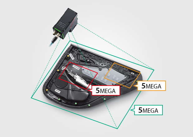
Zeilenkameras nehmen das Bild Zeile für Zeile auf. Das Objekt oder die Kamera werden während der Aufnahme bewegt. Das Bildfeld im Moment der Aufnahme ist ein Schlitz von der Breite des gewünschten Bildes. Dadurch ist es möglich große Bildfelder (0,2m -6m) mit gleichmäßiger Beleuchtung zu erzeugen. Für Zeilenkameras ist die Geschwindigkeit sehr wichtig. Sie bestimmt wie schnell große Flächen erfasst werden können. Mit hoher Geschwindigkeit können auch sehr hohe Auflösungen (1µm) auf sehr kleinen Teilen realisiert werden. Die KEYENCE Zeilenkamera scannt mit 165kHz (165000 Zeilen in einer Sekunde). Kleine Defekte wie z.B. Kratzer, Schmutz und Dellen können sicher erkannt werden. Der neu entwickelte LumiTrax™-Spiegelreflexionsmodus verwendet eine Streifenbeleuchtung zusammen mit den Zeilenkameras, um Oberflächendefekte zu erkennen, die von gewöhnlichen Systemen nicht erkannt werden.
As presented in Figure 2, very small differences exist between the refractive indices of the cells and their surrounding aqueous solutions and within the cells between the cytoplasm (Figure 2(b)) and the cell nucleus (Figure 2(c)). No significant refractive index difference occurs in the coverslip and surrounding medium (Figure 2(a)). Phase contrast makes these tiny differences visible by the use of optical manipulation as, for example, it translates them into differences in intensity that can be visually observed and recorded. The optical effect employed in this case consists of a shift of phase relationships between light wavefronts traveling through different portions of the specimen. During their journey through cell nuclei, cytoplasm, or water, the light waves are shifted (retarded) by small degrees, since these media have slightly different refractive indices (the higher the refractive index of a medium, the smaller the speed or velocity of light in the medium). As a result, a light wave that has passed through a cell nucleus lags behind the light waves that only had to pass through water (compare Figure 2(a) and Figure 2(c)). The amount of lag is called a phase shift. Before their entry into the specimen, the waves are still in phase (wavefronts beneath the coverslip), but this is no longer the case when they have passed through the various materials having different refractive indices. The amount of the phase shift depends on what media (refractive index) the waves have passed through on their paths, and how long the paths were through these media. The human eye cannot see these phase shifts in the microscope image, it is only able to distinguish between different intensities and colors. Therefore, the phase contrast technique uses optical tricks to translate phase shifts into grey values.
Verbesserungen in der Bildverarbeitungssystemtechnologie haben fortschrittliche, automatisierte Inline-Prüfungen für jede Benutzerebene ermöglicht. Es ist nun möglich, 100 % der Produkte auf Hochgeschwindigkeits-Fertigungslinien zu prüfen, sodass fehlerhafte Teile vor der weiteren Verarbeitung oder Freigabe identifiziert werden können. Würden ähnliche Inspektionen manuell von Anwendern durchgeführt werden, wäre dieser Prozess langsamer und weniger zuverlässig.
Dieser Leitfaden kann Benutzern helfen, aus der großen Auswahl an Kameras, Objektiven, Beleuchtungen und Steuergeräten das richtige Bildverarbeitungssystem zu finden. Entdecken Sie Auswahltipps für jedes Gerät durch leicht verständliche Erklärungen mit Diagrammen, Beispielbildern und Prüfbeispielen.
Bildverarbeitungssysteme von KEYENCE können Kameraprüfungen auf einer Vielzahl von Prüfobjektoberflächen durchführen. Ausgereifte Inspektionsalgorithmen, wie z. B. das Defektwerkzeug, können lokale Kontrastveränderungen erkennen, um Kratzer und Flecken zu identifizieren. Da bei der Inspektion nach lokalen Veränderungen gesucht wird, stören äußere Einflüsse wie das Umgebungslicht die Inspektion nicht. Zusätzlich zu den robusten Inspektionswerkzeugen stehen 24 Bildaufbereitungsfilter zur Verfügung, um die Auswirkungen von ungleichmäßiger Beleuchtung, rauen Oberflächen oder Abweichungen zwischen Produkten zu reduzieren. Zwei bemerkenswerte Filter sind die Extraktion von Kratzern, die lineare Fehler auf rauen Prüfobjekten hervorhebt. Weiterhin die Schattierungskorrektur, die scharfe Kontraständerungen hervorhebt, während sie allmähliche Änderungen eliminiert.
As discussed, the split DIC light beams enter and pass through the specimen where their wave paths are altered in accordance with the specimen's varying thickness, slopes, and refractive indices. These variations cause alterations in the wave path of both beams passing through areas of any specimen details lying close together. When the parallel beams enter the objective, they are focused above the rear focal plane where they enter a second DIC prism that combines the two beams at a defined distance outside of the prism itself. This removes the shear (distance between the waves) and the original path difference between the beam pairs. As a result of having traversed the specimen, the paths of the parallel beams are not of the same length (optical path difference) for differing areas of the specimen.
Erin E. Wilson and Michael W. Davidson - National High Magnetic Field Laboratory, 1800 East Paul Dirac Dr., The Florida State University, Tallahassee, Florida, 32310.


 Ms.Cici
 8618319014500