
Relationship between Light and Lens - Why does looking ... - what is the lens
Coating Technologies: Coating technologies play a vital role in defining the filter’s characteristics. Techniques like dielectric coating, where multiple layers of non-conductive materials are deposited, are widely used. These coatings must be stable, durable, and resistant to environmental factors like humidity and temperature changes.
The behavior of the readout electronics serves as the integration’s boundary, which is unrelated to the shutter’s exposure.
Without the container, an integrated sensor is only the sensor’s fundamental technology. It enables various sensor technologies to be “integrated” or combined into a single plug-and-play component.
A notable example is the use of optical bandpass filters in the Hubble Space Telescope. The telescope is equipped with a variety of filters that allow astronomers to observe different wavelengths emitted by distant celestial objects. This capability has been pivotal in making groundbreaking discoveries about the universe, including the rate of its expansion and the properties of distant galaxies.
Astronomy: In astronomy, optical bandpass filters are indispensable for observing celestial bodies and phenomena. They enable astronomers to isolate specific wavelengths emitted by stars, planets, and galaxies, providing insights into their composition and behavior. For instance, a hydrogen-alpha filter is often used to observe solar flares and prominences on the sun, allowing for detailed study of solar activity.
They are amplified using the EM Gain register, sent to the output node, converted to a voltage, grey levels, and then displayed with a PC.
In conclusion, the design and fabrication of optical bandpass filters require a careful balance of material properties, layer precision, and advanced coating techniques. These factors must be meticulously managed to produce filters that meet the stringent demands of diverse optical applications.
The frame-transfer sensor has an active image array (white) and a masked storage array (grey), while the interline-transfer sensor has a portion of each pixel masked (grey).
These electrons can be moved pixel by pixel anywhere on a sensor by employing a positive voltage (orange) to transfer them to another pixel.
Due to its ability to be multiplied up above the noise floor as many times as needed, EMCCDs can now detect tiny signals.
The design and fabrication of optical bandpass filters involve a meticulous selection of materials, layer design, and coating technologies. These factors are critical in determining the filter’s performance, durability, and suitability for specific applications.
This implies that positive voltages can attract electrons, making it possible to move electrons across a sensor by applying a voltage to particular sensor regions.
For example, if a CCD detects a signal of 10 electrons with a read noise of 5 electrons, the signal could be read out at any value between 5 and 15 electrons, depending on the read noise.
Photography: Photographers use optical bandpass filters to enhance image quality and achieve artistic effects. Infrared filters, for example, are popular for creating surreal landscapes where foliage appears white and skies dark, highlighting contrasts not visible to the naked eye. Such filters are instrumental in both artistic and scientific photography, including aerial and environmental surveying.
A full-frame CCD sensor is a kind shown in Figure 2, although there are also additional designs known as frame-transfer CCD and interline-transfer CCD.
EMCCDs provide quicker and more sensitive imaging than CCDs, making them ideal for photon counting or low-light imaging devices.
Additionally, each ADC has to read out considerably less data than a CCD/EMCCD ADC, which must read out the complete sensor because there is an ADC for every column.
Each type of optical bandpass filter serves a unique purpose in the world of optics. The choice of filter depends on the specific requirements of the application, such as the precision of wavelength selection, environmental tolerance, and the intensity of light that needs to be managed. Understanding the strengths and limitations of each filter type empowers engineers and scientists to make informed decisions for their optical systems.
Therefore, in addition to having a lot of pixels, factors like drive technology, quantum efficiency, and pixel size structure all impact imaging performance in different ways.
There are two major types of image sensors: CCD, or charge-coupled device, and CMOS, or complementary metal oxide semiconductor.
Balance the cost against the performance benefits. While higher-quality filters may come at a premium, they often provide better performance and longevity, which is often more cost-effective in the long run, especially for critical applications.
Understanding the key specifications and performance parameters of optical bandpass filters is essential for selecting the right filter for specific applications. The primary specifications include bandwidth, center wavelength, and transmission levels, each playing a crucial role in determining the filter’s performance.
Opticalbandpass filterdesign
CMOS sensor technology allows for greater speeds due to its parallel operation, unlike CCD and EMCCD which rely on different methods of sequential operation.
An image signal processor (ISP) is a processor that receives a raw image from the image sensor and outputs a processed version of that picture (or some data associated with it).
Furthermore, the precision of an optical bandpass filter is defined by its bandwidth, which can vary from very narrow (few nanometers) for high-precision applications to relatively broad for less critical applications. The steepness of the filter’s transition from blocking to transmitting (known as the edge steepness or transition width) also plays a vital role in its performance, especially in applications requiring high spectral resolution.
A pixel (blue squares) is struck by photons (black arrows), which are then transformed into electrons (e-), which are then stored in a pixel well (yellow).
While CCD and EMCCD technologies were popular for scientific imaging, sCMOS technology has emerged in recent years as the best option for imaging in the biological sciences.
Ensure the filter is compatible with your existing optical system, including size, mounting requirements, and spectral compatibility. This is crucial for integrating the filter seamlessly into your setup without needing additional modifications.
In the realm of optical engineering and photonics, optical bandpass filters stand as essential yet often underappreciated components. These filters, integral in managing light wavelengths, are crucial in a vast array of applications – from enhancing astronomical observations to advancing biomedical imaging technologies.
Camera Sensor integration, image sensor integration, and camera image processing methods are widely utilized in various applications
The basis for how digital cameras take and create images is thus the camera sensor, which is essential in transforming light into digital information that can be further processed and saved.
The market for complementary metal-oxide semiconductors, or CMOS and sCMOS image sensors, has grown significantly in recent years.
Optical imaging systems often generate panchromatic, multispectral, and hyperspectral imagery using visible, near-infrared, and shortwave infrared spectrums.
The choice of the appropriate camera sensor has become extremely important and varies from product to product because cameras have a wide variety of uses in many industries.
Semrockbandpass Filter
Biomedical Imaging: In the biomedical field, these filters are critical in fluorescence microscopy. They allow for the observation of specific cellular components tagged with fluorescent markers, aiding in the diagnosis and research of diseases. By isolating the wavelengths emitted by these markers, researchers can obtain clear, precise images of cellular structures and processes.
The primary purpose of these sensors is to produce images for digital cameras, digital video cameras, and digital CCTV cameras.
After being exposed to light and changing from photons to photoelectrons in a CCD, the electrons are transported down the sensor row by row until they reach the readout register, which is not exposed to light.
Disadvantages: They usually have broader bandwidths and less precise wavelength control, with lower peak transmission levels.
This was accomplished in several ways via EMCCDs. The cameras’ back illumination (which raises the QE to over 90%) and massive pixels (16-24 m) significantly raise their sensitivity.
Bandpass filtercalculator
Additionally, as the demand for narrower bandwidths and higher transmission efficiency increases, particularly in sophisticated applications like telecommunications and medical imaging, the fabrication process becomes increasingly complex, requiring cutting-edge technology and expertise.
Machine vision covers flat panel displays, PCBs, semiconductors, warehouse logistics, transportation systems, crop monitoring, and digital pathology.
Layer Design: Optical bandpass filters typically comprise multiple thin layers of different materials. These layers create the required interference patterns to select specific wavelengths. The precision in the thickness and uniformity of these layers is crucial. Variations can significantly impact the filter’s bandwidth and center wavelength. Advanced techniques like ion-beam sputtering and vacuum deposition are employed to achieve the necessary precision.
To deliver a high-quality image for a specific camera sensor and use case, an ISP could carry out several procedures, including black level reduction, noise reduction, AWB, tone mapping, color interpolation, autofocus, etc.
The quality of the filter is paramount. This includes the uniformity of the coating, the quality of the substrate, and the overall fabrication precision. High-quality filters offer better performance, more accurate results, and reduced likelihood of introducing artifacts or errors into your system.
This includes camera integration, camera image processing, CMOS image sensor technology tuning, and other related capabilities.
Optical bandpass filters are specialized components in the field of photonics, designed to transmit light within a specific wavelength range while blocking light outside this range. These filters are pivotal in applications where precise wavelength selection is critical, such as in spectroscopy, laser line separation, or fluorescence microscopy.
Opticalbandpass filter
One of the primary challenges in fabricating optical bandpass filters is maintaining the precision of the layer thickness and material quality across the entire filter surface. Any inconsistency can lead to variations in filter performance.
In summary, optical bandpass filters are versatile tools that significantly enhance the capabilities of various technologies in astronomy, photography, biomedical imaging, and laser systems. Their ability to selectively transmit specific wavelengths of light makes them invaluable in both scientific research and practical applications.
IRBandpass filter
When purchasing optical bandpass filters, several key factors must be considered to ensure that the filter meets the specific requirements of your application. Understanding these factors can help in selecting the right type of filter while ensuring quality and durability.
The sensor collects light and transforms it into an electrical signal that is subsequently processed to create a digital image, much like the retina in a human eye does the same thing by translating light into nerve impulses that the brain can understand.
Customers building next-generation camera sensor products for various applications may rely on Camera Image Processing to provide the best solutions.
Nowadays, charge-coupled devices(CCD camera sensors) and complementary metal oxide semiconductor technology (CMOS) imagers make up the majority of sensors.
The images are processed by imaging software on this node, amplified to readable voltage, and transformed into digital grey levels using an ADC.
Photons hit a pixel, converting to electrons that move to the sensor’s readout register, then to the output node where they become voltage, then grey levels, and finally displayed on a PC.
The EM Gain register now becomes the primary point of distinction. Impact ionization is a technique EMCCDs to drive more electrons out of the silicon sensor size, doubling the signal.
Advantages: These filters have high durability and excellent resistance to heat and humidity. They offer sharp cutoffs between transmitted and reflected wavelengths.
From consumer to computer vision to industrial, defense, multimedia, sensor networks, surveillance, automotive, and astronomy.
The most critical aspect to consider is the filter’s optical specifications, which include bandwidth, center wavelength, and transmission levels. Ensure these align with your application’s requirements. For high-precision applications, like in scientific research, look for filters with narrow bandwidths and accurate center wavelengths. For broader applications, such as in general photography, slightly less precise specifications may be acceptable.
At their core, optical bandpass filters operate on the principle of wavelength selectivity. This is achieved through various methods, such as interference, absorption, or a combination of both. Interference filters, for instance, utilize multiple thin layers of different materials to create constructive and destructive interference patterns, allowing only certain wavelengths to pass through. Absorptive filters, on the other hand, rely on materials that inherently absorb specific wavelengths while transmitting others.
EMCCD Fundamentals – Camera Sensor TechnologiesThe above image explains, How an EMCCD sensor works. Photons hit a pixel and are converted to electrons, which are then shuttled down the sensor integration to the readout register.
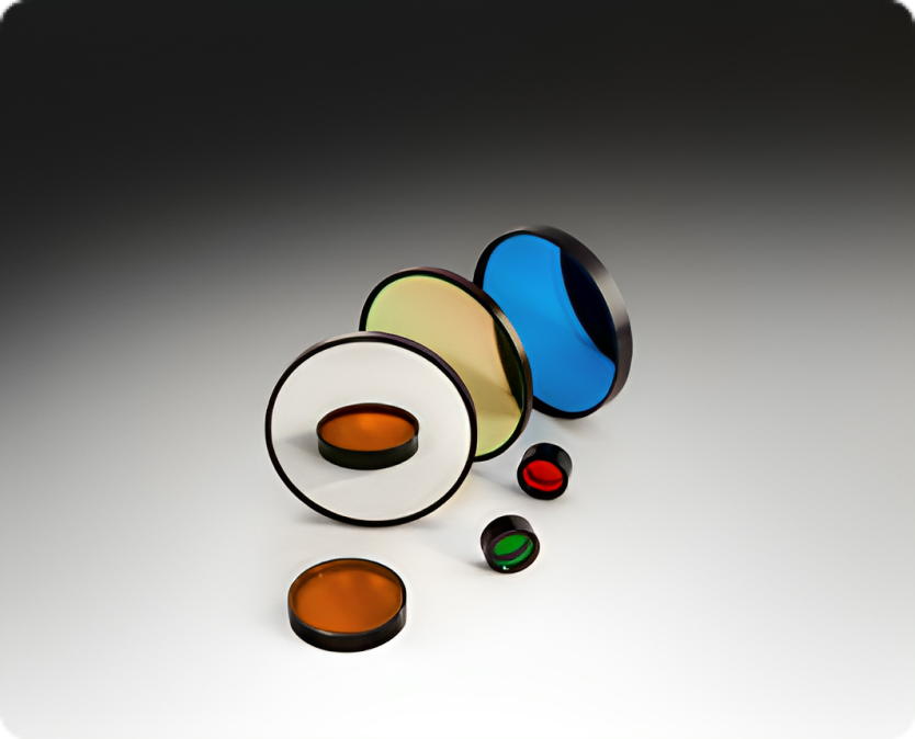
Optical bandpass filters are pivotal in numerous applications, owing to their ability to selectively transmit specific wavelength ranges. Broadly categorized into interference, absorptive, and dichroic filters, each type comes with its unique set of characteristics, advantages, and ideal applications.
On a sensor, electrons can be carried in any direction in this way, and they are often moved to a location where they can be amplified and turned into a digital signal, which can then be presented as an image.
Applications: Often used in fluorescence microscopy (for directing specific wavelengths to the detector), RGB color mixing in projectors, and advanced lighting systems.
The incident light (photons) is focused by a lens or other optics and is received by the image sensor in a camera system.
This implies that the pixel converts a photon into an electron and that the electron is then instantly changed into a readable voltage while still on the pixel.
According to Skyquestt, With a projected size of USD 16.25 billion in 2019 and a projected growth rate of 9.6% during the forecast period (2024–2031), the image sensor market is expected to reach USD 39 billion by 2031 from USD 16.36 billion in 2023.
For sensitive, quick imaging of a range of samples for several applications, quantitative scientific cameras are essential. Since the invention of the first cameras, camera technology has developed significantly.
Disadvantages: They can be sensitive to angle and temperature variations, which might alter their spectral characteristics.
Another challenge is ensuring the filter’s longevity and resistance to environmental factors, which requires robust coating technologies and stringent quality control during the fabrication process.
Signal Conversion: An electrical signal that could be weak is produced by the sensor. Analog electronics (3) increase this signal by amplifying it.
Bandpass filter lightreplacement
Description: Dichroic filters are a type of interference filter that reflects unwanted wavelengths while transmitting the desired range. They are constructed with multiple thin layers of dielectric materials.
Electrons go from the image array to the masked array, and then onto the readout register in a manner that is remarkably similar to frame-transfer CCDs.
The image processing sector is currently one of the global businesses with the fastest growth rates, and as a result, it is a crucial area of engineering study.
This technology’s lack of sensitivity and speed constrained the number of samples that could be scanned at acceptable levels.
For those seeking to delve deeper into the world of optical bandpass filters, the following references and sources provide extensive information and insights:
Advantages: Absorptive filters are generally more robust and less sensitive to angle and temperature changes compared to interference filters.
UVBandpass filter
Due to inadequate illumination and other environmental factors, the captured image may contain some unnecessary elements despite each specific sensor, processor, and lens combination.
Image Processing: The digital data is routed to the image processor (5), where it is subjected to several enhancements and modifications, including sharpening and color correction.
Temporary Storage: Processed photos may be stored in the camera’s buffer (6) indefinitely while they wait to be written to the memory card.
When an EMCCD receives a signal of 5 electrons, and the EM Gain is set to 200, the output node will receive a signal of 1000 electrons.
As CMOS sensors have a far lower read noise than CCD/EMCCD, they can work with weak fluorescence or live cells and move electrons much slower than the projected maximum speed.
Obtaining the ideal image or video quality is tricky for each use scenario. A lot of filtering and iterations are necessary to attain a desirable outcome.
The sensor’s ability to transmit data as either a voltage or a digital signal to the following stage will depend on whether it is CCD or CMOS.
These neural networks will be able to detect suspicious behavior and transmit an alarm in real time, instead of depending just on motion detection.
Description: These filters use multiple thin-film layers to create constructive and destructive interference, allowing only certain wavelengths to pass through. They are known for their high precision and narrow bandwidths.
Compared to CCD/EMCCD technology, this combination enables CMOS sensors to operate parallel and analyze data more quickly.
ThorlabsBandpass Filter
A sensor transforms a physical event into a quantifiable analog voltage, or occasionally a digital signal, which is then sent for reading or additional processing or transformed into a display that is readable by humans.
Advantages: Interference filters offer excellent wavelength selectivity and high transmission efficiency within their passband. They are highly customizable in terms of bandwidth and center wavelength.
Applications: Widely used in spectroscopy, astronomy (for isolating specific spectral lines), and laser-based applications (for filtering specific laser wavelengths).
Consider the maintenance needs and durability of the filter. A filter that is easy to clean and resistant to scratches and other damage can be a more cost-effective choice in the long run. Check for any special handling or storage requirements to maintain the filter’s performance over time.
The sensor collects light and transforms it into an electrical signal that is subsequently processed to create a digital image, much like the retina in a human eye does the same thing by translating light into nerve impulses that the brain can understand.
This article, “Bandpass Filters Explained: A Detailed Guide,” is designed to unfold the layers of complexity surrounding optical bandpass filters. Aimed at engineers, scientists, and technical enthusiasts, it delves into the principles, types, applications, and nuances of selecting the right optical bandpass filters. Whether you are a seasoned expert or a curious newcomer in the field of optical technology, this guide aims to illuminate the critical aspects of these filters, enhancing your understanding and aiding in informed decision-making for your optical projects.
Optical bandpass filters are integral components in a wide range of scientific and technical applications, from astronomy and photography to biomedical imaging and laser systems. Understanding their types, from interference to absorptive and dichroic filters, and their respective advantages, is crucial for their effective utilization. Key specifications like bandwidth, center wavelength, and transmission levels play a pivotal role in their performance and suitability for specific tasks.
Laser Systems: Optical bandpass filters are also key components in laser systems, particularly in laser-based measurement and communication technologies. They ensure the purity of the laser light by filtering out unwanted spectral noise, thus enhancing the system’s accuracy and efficiency.
All electrons have a negative charge that underlies the operation of all the sensor types covered here (the electron symbol being e-).
The current generation of intelligent devices, which represent a quantum jump in sophistication, is made possible by camera competence.
The growth behind these image sensors is due to the growing need for high-performance, low-power, and reasonably priced imaging solutions across a range of industries.
Every pixel is transformed into an electrical charge, the strength of which is correlated with the amount of light it was able to collect.
Research the manufacturer’s reputation in the market. Established manufacturers with a history of producing high-quality optical filters are generally more reliable. Look for reviews, testimonials, and case studies that demonstrate their expertise and product performance.
3D Imaging: There are now more uses for CMOS image sensors in augmented reality, industrial inspection, and healthcare thanks to their development of 3D imaging capabilities.
Because the speed at which electrons are moved around a sensor increases read noise, CCDs move electrons much slower than their maximum potential speed.
Each of these sources provides a unique perspective and level of detail on optical bandpass filters, making them invaluable for anyone looking to enhance their understanding or research in this field. Whether you’re a student, a researcher, or a professional, these references will serve as a solid foundation for further exploration and study.
Digital Conversion: After being amplified, the signal is passed to an analog-to-digital converter (4), which changes it into digital data that the camera can process more easily.
Description: These filters rely on the intrinsic properties of materials to absorb unwanted wavelengths while transmitting the desired range. They are often made from colored glass or dyed plastics.
Users can select a number between 1 and 1000 to have their signal multiplied that many times in the EM Gain register as part of this step-by-step EM process.
It is divided into four categories, such as contact image sensor (CIS), charge-coupled device (CCD) image sensor, front side illuminated (FSI), backside illuminated (BSI), and complementary metal oxide semiconductor (CMOS) image sensor.
Photons hit a pixel, are converted to electrons, and then to the voltage on the pixel. Each column is read out separately by individual ADCs and then displayed with a PC.
The development and spread of consumer electronics with imaging capabilities underscore the increasing importance of camera image processing.
By selecting the best camera manufacturer technology for your imaging system, you can enhance all aspects of your studies and conduct quantitative research.
Filter Materials: The choice of material is paramount in filter design. Materials like fused silica, borosilicate glass, and various types of crystals are commonly used. Each material has distinct optical properties, like transmission ranges and thermal stability, influencing the filter’s performance. For instance, fused silica is preferred for its high transmission in the ultraviolet (UV) range, making it suitable for UV applications.
According to datahorizzonresearch, the market growth of CMOS and sCMOS image sensor market size was valued at USD 23.3 Billion in 2023 and is expected to reach a market size of USD 40.8 Billion by 2032 at a CAGR of 6.4%.
CCD sensor Works – Camera Sensor TechnologiesThe above image explains the Different types of CCD sensors. The full-frame sensor is also displayed. Grey areas are masked and not exposed to light.
AI Transforming Photography: Camera technology is being revolutionized by AI and machine learning, with possible uses ranging from improving image authenticity to countering bogus AI-generated photos.
Applications: Common in photography (for color balancing), basic scientific instruments, and educational tools where extreme precision is not critical.
The information transferred to the following stage by the sensor will be either a voltage or a digital signal, depending on whether it is a CCD or CMOS sensor.
High-Resolution Sensors: There is a growing trend towards higher resolution CMOS image sensors, enabling sharper and more detailed images.
To evaluate the camera sensors’ tuning, image quality, and image resolution, various types of labs tools are required, such as;
When selecting an optical bandpass filter, it’s essential to consider factors such as optical specifications, quality, manufacturer reputation, and compatibility with existing systems. The right choice not only enhances the efficiency and accuracy of your application but also contributes to the longevity and reliability of your optical system. Therefore, investing time in understanding these filters and carefully selecting the appropriate one for your needs is imperative for achieving optimal results in any field where precise light manipulation is required.
The image sensor in a camera system receives incident light, or photons, that have been focused by means of a lens or other optics.
Optical bandpass filters have revolutionized various fields by their ability to precisely control the wavelengths of light passing through them. Their applications span from astronomy to biomedical imaging, each utilizing the unique properties of these filters.
What sets optical bandpass filters apart from other types of filters, like longpass or shortpass filters, is their ability to isolate a band of wavelengths. Longpass filters only block wavelengths shorter than a certain threshold, and shortpass filters do the opposite. However, an optical bandpass filter provides a ‘window’ of transmitted light, defined by both an upper and a lower cutoff wavelength. This characteristic makes them exceptionally useful in systems where both the rejection of unwanted light and the passage of a specific spectral region are necessary.
Light entering a digital camera through the lens hits an image sensor. The camera processes the signal that the image sensor outputs to produce image data, which is then saved on the memory card.
An integrated circuit that is sensitive to light and uses photons and electrons to create images is called a charge-coupled device, or CCD. Pixels are separated from the image elements using a CCD sensor.
In summary, when buying an optical bandpass filter, it’s important to thoroughly evaluate your specific application needs, the quality and specifications of the filter, the manufacturer’s reputation, and the overall cost-effectiveness. Making an informed decision based on these factors will ensure that you select a filter that meets your requirements and provides reliable performance.
EMCCDs are far more sensitive than CCDs thanks to the combination of large pixels, back illumination, and electron multiplication.
CMOS sensors use an on-chip analog-to-digital converter (ADC) to transform photons into electrons, voltage, and finally a digital value.
Moreover, barcode readers, astronomical telescopes, and scanners all use these electronic chips. Low-cost consumer gadgets are possible thanks to CMOS’s inexpensive manufacture.
The transformation of light photons into electrons is the first process for a sensor (known as photoelectrons). Quantum efficiency (QE), which is displayed as a percentage, is the efficiency of this conversion.
Different applications may have unique requirements. For instance, filters used in harsh environmental conditions, such as in outdoor photography or industrial settings, should have robust environmental resistance. In contrast, filters used in controlled environments, like laboratories, can focus more on spectral precision.
Each of these parameters must be carefully considered in relation to the intended application. For instance, in high-precision scientific instruments, narrow bandwidths, precise center wavelengths, and high transmission levels are typically necessary for accurate and efficient performance. In contrast, for broader commercial applications, there may be more flexibility in these specifications. Ultimately, the optimal balance of these parameters depends on the specific requirements of the application, including considerations of the light source, the sensitivity of detection equipment, and the nature of the target signal or image.


 Ms.Cici
 8618319014500