
Advantages telecentricity - telecentric lens
Mixing and MatchingC-mount and CS-mount components have identical threads, but lenses and cameras of different mount types should not be directly attached to one another. If this is done, the lens' focal plane will not coincide with the camera's sensor plane due to the difference in FFD, and the image will be blurry.
These adapters are a subset of our entire line of optical component thread adapters. To view our entire line, please see our Interactive Adapters Selection Guide.
It is critical to check the lens and camera parameters to determine whether the components are compatible, an adapter is required, or the components cannot be made compatible.
Flange focal distance (FFD) values for cameras and lenses assume only air fills the space between the lens and the camera's sensor plane. If windows and / or filters are inserted between the lens and camera sensor, it may be necessary to increase the distance separating the camera's flange and sensor planes to a value beyond the specified FFD. A span equal to the FFD may be too short, because refraction through windows and filters bends the light's path and shifts the focal plane farther away.
The CS- and C-mount standards both use 1.00"-32 threads, but C-mount lenses have a flange focal distance (FFD) that is 5 mm longer than CS-mount lenses, as illustrated in the diagram to the far right. Spacer length is defined for each adapter as the distance depicted by the diagram to the near right. The CML05 adapter is 5 mm long and acts as a spacer, enabling the use of C-mount lenses with CS-mount cameras; see the Insights tab for more details.
Thread SeriesMost screws are identified by their thread series. Thread series are denoted by the major diameter and density of threads. Unified threads specify density in threads per inch, while Metric threads specify the thread pitch. For example, in the Unified nomenclature, a 1/4"-20 cap screw has a 1/4" diameter barrel and the pitch is 20 threads per inch (TPI). In metric nomenclature, an M4 x 0.7 cap screw has a 4 mm barrel and the pitch is 1 thread per 0.7 mm. The term M4 x 0.7 is often shortened to just M4.
Thread FormA thread form is a set of rules that define the features' scale relative to one another. Common thread forms include the Unified Screw Thread Form, used in the United States of America and measured in imperial units, and the ISO Metric Screw Thread Form, used in many parts of the world and measured with the International System of Units. There are many thread forms in the Unified screw thread standard designated by either UN, which defines a flat root contour, or UNR, which defines a round root contour. These can be further described by appending more letters. For example, an extremely fine thread with a flat root contour is designated UNEF. Those forms which are not standardized by the Unified screw thread system are designated UNS.
While travelling through the optic, the ray approaches the optical axis at a slower rate than a ray travelling the same distance in air. After exiting the optic, the ray's angle with the axis is again θo , the same as a ray that did not pass through the optic. However, the ray exits the optic farther away from the axis than if it had never passed through it. Since the ray refracted by the optic is farther away, it crosses the axis at a point shifted Δf beyond the other ray's crossing. Increasing the optic's thickness widens the separation between the two rays, which increases Δf.
A benefit of the adjustable C-mount adapter is that it can tune the spacing between the lens and camera over a 1.8 mm range, when the window / filter and retaining ring are in place. Changing the spacing can compensate for different effects that otherwise misalign the camera's sensor plane and the lens' focal plane. These effects include material expansion and contraction due to temperature changes, positioning errors from tolerance stacking, and focal shifts caused by a substitute window or filter with a different thickness or refractive index.
1.000"-32 ThreadsImperial threads are properly described by their diameter and the number of threads per inch (TPI). In the case of both these mounts, the thread diameter is 1.000" and the TPI is 32. Due to the prevalence of C-mount devices, the 1.000"-32 thread is sometimes referred to as a "C-mount thread." Using this term can cause confusion, since CS-mount devices have the same threads.
The following is a general overview of screw threading. For more details regarding specifications and dimensions, please consult the Machinery's Handbook, available for purchase at many bookstores.
An approach some lenses use to compensate for this is to allow the user to vary the lens focus to points "beyond" infinity. This does not refer to a physical distance, it just allows the lens to push its focal plane farther away. Thorlabs' Kiralux™ and Quantalux® cameras include adjustable C-mount adapters to allow the spacing to be tuned as needed.
If it is impossible to get a sharp image of objects at infinity, despite tuning the lens focus, try adjusting the camera's adapter. This can compensate for shifts due to tolerance and environmental effects and bring the image into focus.
Thread ClassThe tolerances and allowances on a thread series are given by a thread class. Unified thread classes are alphanumeric identifiers starting with a number from 1 through 3, where 1 is the loosest tolerance and 3 is the tightest, and either A for external threading or B for internal threading.
To Infinity and BeyondIt is important to many applications that the camera system be capable of capturing high-quality images of objects at infinity. Rays from these objects are parallel and focused to a point closer to the lens than rays from closer objects (Figure 9). The FFDs of cameras and lenses are defined so the focal point of rays from infinitely distant objects will align with the camera's sensor plane. When a lens has an adjustable focal range, objects at infinity are in focus at one end of the range and closer objects are in focus at the other.
The C-mount and CS-mount camera system standards both include 1.000"-32 threads, but the two mount types have different flange focal distances (FFD, also known as flange focal depth, flange focal length, register, flange back distance, and flange-to-film distance). The FFD is 17.526 mm for the C-mount and 12.526 mm for the CS-mount (Figures 1 and 2, respectively).
FOVcalculator
Measuring Flange Focal DistanceMeasurements of flange focal distance are given for both lenses and cameras. In the case of lenses, the FFD is measured from the lens' flange surface (Figures 1 and 2) to its focal plane. The flange surface follows the lens' planar back face and intersects the base of the external 1.000"-32 threads. In cameras, the FFD is measured from the camera's front face to the sensor plane. When the lens is mounted on the camera without an adapter, the flange surfaces on the camera front face and lens back face are brought into contact.
Not Just Theory: Camera Design ExampleThe C-mount, hermetically sealed, and TE-cooled Quantalux camera has a fixed 18.1 mm spacing between its flange surface and sensor plane. However, the FFD (f ) for C-mount camera systems is 17.526 mm. The camera's need for greater spacing becomes apparent when the focal shift due to the window soldered into the hermetic cover and the glass covering the sensor are taken into account. The results recorded in the table beneath Figure 9 show that both exact and paraxial equations return a required total spacing of 18.1 mm.
The major diameter is taken from the crests of a thread while the minor diameter is taken from the roots. For most screws, crests and roots do not terminate at a sharp point, so crest and root truncation values are included in the definitions of major and minor diameter. The pitch diameter is approximately halfway between the major and minor diameters.
The SM1 threads integrated into the camera housings are intended to facilitate the use of lens assemblies created from Thorlabs components. Adapters can also be used to convert from the camera's C-mount configurations. When designing an application-specific lens assembly or considering the use of an adapter not specifically designed for the camera, it is important to ensure that the flange focal distances (FFD) of the camera and lens match, as well as that the camera's sensor size accommodates the desired field of view (FOV).
The CML05 adapter has C-mount (1.00"-32) threads and adds 5 mm between a lens and a camera when mounted. Used as a spacer, it enables the use of C-mount lenses with CS-mount cameras.

When an optic with plane-parallel sides and a higher refractive index (nm ) is placed in the ray's path, refraction causes the ray to bend and take a shallower angle (θm ) through the optic. This angle can be determined from Snell's law, as described in the table and illustrated in Figure 9.
While any adapter converting from SM1 to 1.000"-32 threads makes it possible to attach a C-mount or CS-mount lens to one of these cameras, not every thread adapter aligns the lens' focal plane with a specific camera's sensor plane. In some cases, no adapter can align these planes. For example, of these scientific cameras, only the Zelux can be configured for CS-mount lenses.
The position of the lens' focal plane is determined by a combination of the lens' FFD, which is measured in air, and any refractive elements between the lens and the camera's sensor. When light focused by the lens passes through a refractive element, instead of just travelling through air, the physical focal plane is shifted to longer distances by an amount that can be calculated. The adapter must add enough separation to compensate for both the camera's FFD, when it is too short, and the focal shift caused by any windows or filters inserted between the lens and sensor.
An experiment was conducted to compare the thermal isolation of our thermally insulating adapters (SM1A4TS, SM1A9TS, SM1A3TS, and SM1A10TS) presented at the bottom of this page with that of our traditional aluminum adapters. During the experiment, an aluminum adapter and a thermally isolating black Delrin®* adapter were each used to connect two lens tubes. Then, one of the lens tubes was externally heated to 60 °C using a foil heating element that had been attached to that lens tube’s outer surface.
With an adapter, a C-mount lens can be used with a CS-mount camera (Figures 3 and 4). The adapter increases the separation between the lens and the camera's sensor by 5.0 mm, to ensure the lens' focal plane aligns with the camera's sensor plane.

Made for Each Other: Cameras and Their AdaptersFixed adapters are available to configure the Zelux cameras to meet C-mount and CS-mount standards (Figures 6 and 7). These adapters, as well as the adjustable C-mount adapters attached to the passively cooled Kiralux and Quantalux cameras, were designed specifically for use with their respective cameras.
Different effects, including temperature changes and tolerance stacking, can result in the lens and / or camera not exactly meeting the FFD specification. When the lens' actual FFD is shorter than the camera's, the camera system can no longer obtain sharp images of objects at infinity (Figure 11). This offset can also result if an optic is removed from between the lens and camera sensor.
In caso di password dimenticata e problemi con la procedura di recupero, potete contattare il nostro team e richiedere una nuova password temporanea, vi verrà inviata al piu presto.
A Case of the Bends: Focal Shift Due to RefractionWhile travelling through a solid medium, a ray's path is straight (Figure 8). Its angle (θo ) with the optical axis is constant as it converges to the focal point (f ). Values of FFD are determined assuming this medium is air.
In contrast, the shorter FFD of CS-mount lenses makes them incompatible for use with C-mount cameras (Figure 5). The lens and camera housings prevent the lens from mounting close enough to the camera sensor to provide an in-focus image, and no adapter can bring the lens closer.
Since their flange focal distances are different, the C-mount and CS-mount components are not directly interchangeable. However, with an adapter, it is possible to use a C-mount lens with a CS-mount camera.
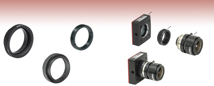
Flexiblity and Quick Fixes: Adjustable C-Mount AdapterPassively cooled Kiralux and Quantalux cameras consist of a camera with SM1 internal threads, a window or filter covering the sensor and secured by a retaining ring, and an adjustable C-mount adapter.
Features of a ThreadA thread consists of three repeating features: a crest, flank, and root (see drawing to the right). Except in special cases, threads have symmetrical sides inclined at equal angles when a vertical line is drawn through the center of a crest or root. The distance between corresponding points on adjacent threads is known as the pitch of the thread. The flank angle is defined as the angle the flank makes with a perpendicular ray drawn from the screw axis. Unless otherwise stated, threads have a flank angle of 30°, resulting in a total angle between flanks of 60°. Each feature is shown in the diagram to the right.
All Kiralux™ and Quantalux® scientific cameras are factory set to accept C-mount lenses. When the attached C-mount adapters are removed from the passively cooled cameras, the SM1 (1.035"-40) internal threads in their flanges can be used. The Zelux scientific cameras also have SM1 internal threads in their mounting flanges, as well as the option to use a C-mount or CS-mount adapter.
If the lens' FFD is larger than the camera's, images of objects at infinity fall within the system's focal range, but some closer objects that should be within this range will be excluded. This situation can be caused by inserting optics between the lens and camera sensor. If objects at infinity can still be imaged, this can often be acceptable.
Scroll down to read about compatibility between lenses and cameras of different mount types, with a focus on Thorlabs' scientific cameras.
If making changes to the optics between the lens and camera sensor, the resulting focal plane shift should be calculated to determine whether the separation between lens and camera should be adjusted to maintain good alignment. Note that good alignment is necessary for, but cannot guarantee, an in-focus image, since new optics may introduce aberrations and other effects resulting in unacceptable image quality.
Angolo di campo occhio umano
Metric threads have a slightly more complex tolerancing method that uses tolerancing grades, designated by a number 3 through 9; and tolerancing positions, which use letters e through h. Grades provide a measure of the tolerance itself: the smaller the number, the tighter the tolerance. Positions denote the distance of the tolerance from the pitch diameter. Uppercase positioning letters indicate internal threads while lowercase positioning letters indicate external threads.
This page contains all of our Optical Component Thread Adapters that feature C-mount (1.00"-32) threading. Adapters featuring either internal or external threads are available.
I dati personali secondo quanto previsto l’articolo 4 del gdpr e s.m.i. saranno trattati In conformità alla normativa in materia di tutela dei dati personali. Leggi la Privacy Policy completa
Adjusting the camera's adapter may be necessary to obtain sharp images of objects at infinity. When an object is at infinity, the incoming rays are parallel, and location of the focus defines the FFD of the lens. Since the actual FFDs of lenses and cameras may not match their intended FFDs, the focal plane for objects at infinity may be shifted from the sensor plane, resulting in a blurry image.
Field of View
Quoting from the Machinery's Handbook, 29th Edition, p. 1885: "To designate the tolerance class, the grade and position of the pitch diameter is shown first followed by that for the major diameter in the case of the external thread or that for the minor diameter in the case of the internal thread, thus 4g6g for an external thread and 5H6H for an internal thread. If the two grades and positions are identical, it is not necessary to repeat the symbols, thus 4g, alone, stands for 4g4g and 5H, alone, stands for 5H5H."
During the heating process, simultaneous temperature readings were recorded in 30 second intervals for both the heated and unheated lens tube in each system. The measured results are shown in the plot to the right. From the graph, it is clearly evident that there is far less heat transfer when using one of our thermally isolating adapters to connect two lens tubes than exists when using an aluminum adapter.
Thorlabs' SM Series ThreadsThreading specifications for our SM threads, utilized in our lens tube and cage system components, are given below so that you can machine mating components to suit your application. Most SM series threads utilize a non-standard Unified thread form, indicated by the letters UNS, with a 30° flank angle and a thread class of 2A and 2B. The exception is our SM30 series thread, which is a Metric thread form with a 30° flank angle and a tolerance of 6H/6g. We also offer products with C-Mount and RMS threads, and the specifications for these threads are given below for reference. Please note that other manufacturers may have different tolerances for C-Mount and RMS threads. For other thread specifications that are not listed here, please contact Tech Support.


 Ms.Cici
 8618319014500