
Niagara Falls Illumination Requests - illumination application
The focal length of the lens describes the distance between the lens and the focused image on the sensor. As light passes through the lens it will either converge (positive focal length) or diverge (negative focal length), however within cameras the focal length is predominately positive. Shorter focal lengths converge the light more strongly (i.e. at a sharper angle) to focus the subject being imaged. Longer focal lengths, in comparison, converge the light less strongly (i.e. at a shallower angle) in order to focus the image.
Depthof field photography
Sensor size is determined by both the size of the pixels and number of pixels on the sensor. This can be optimized for each application, with larger sensors optimal for sensitivity limited applications, and smaller sensors optimal for resolution limited applications.


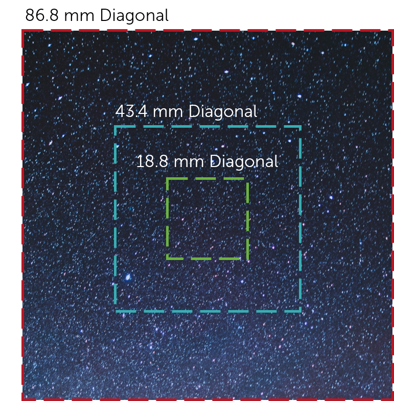
Field of view (FOV) is the maximum area of a sample that a camera can image. It is related to two things, the focal length of the lens and the sensor size. Figure 1 shows a comparison between the field of view and the size of the sensor. Assuming that the focal length of the lens is the same, the larger the sensor the larger the field of view.
Acton optics and coatings provide ultra-precision optical components and coatings with an emphasis on the UV/VUV spectral regions.
Field of View PhotographyEFNL
This means that the distance of the focal length is determined by how strongly the light is converged by the lens in order to focus the subject being imaged. This, in turn, influences the angle from the horizonal of light that can be captured by the lens. This is known as the angular field of view (AFOV) and is required to determine the overall FOV. The AFOV is the angle between any light captured at the horizonal, and any light captured at the edge (as shown in Figure 2). If you have a fixed sensor size, altering the focal length will alter the AFOV and therefore the overall FOV. A shorter focal length provides a larger AFOV view, and therefore a larger FOV. The same is true but vice versa for longer focal lengths, as indicated in Figure 2.
Field of Photography
See how others are using our high-performance cameras, spectrographs and optics-based solutions to advance their research and application.
Field of viewcamera
The calculation does not consider cladding modes. These, however, will usually exhibit much higher losses, so that after some propagation distance only the power in guided modes remains.
The sensor size is determined by both the number of pixels on the sensor, and the size of the pixels. Different sized pixels are used for different applications, with larger pixels used for higher sensitivity, and smaller pixels used for higher spatial resolution (find out more on Pixel Size and Camera Resolution).
Where D is the full display image dimensions (either horizontal or vertical), and d is the target dimensions (either horizontal or vertical).
The calculated results are displayed below when you press the button “Calculate launch efficiency”. For each guided mode of the fiber, the fraction of the incident power which gets into that mode is displayed numerically and graphically. (For modes with non-zero <$l$> value, the two possible orientations are listed separately: the one with the <$\sin l \varphi$> dependence is indicated with a negative <$l$> value.)
Field of view
To measure the FOV of UV, visible and infrared cameras, optical tests are commonly used. During the test, light is focused from a black body (an object that absorbs all light that falls on it) onto a test target at the focal place. By using a set of mirrors, a virtual image can be created that is at an infinitely far distance.
The results are obtained by calculating a complex overlap integral containing the transverse input beam profile and the mode profile.
You can also determine whether or not the Fresnel reflection of the (uncoated) fiber end is taken into account, and whether or not modes with very small power are displayed.
Field of ViewSportsPhotography
Figure 3 shows a simplified version of how these assumptions allow for AFOV calculation. By using trigonometry, the AFOV can be expressed as:
Here we explain in detail how the RP Fiber Calculator software is used. Each of the menu items explains one of the tabs.
For example, in some diagram you could vary the magnitude of any kind of alignment error, of some parameter of the index profile, or the wavelength, and plot anything you like.
Field of Viewfacebook
Field of view defines the maximum area of a sample that a camera can image, determined by the focal length of the lens and the sensor size.
Here you can calculate how a Gaussian laser beam is coupled into a fiber. More precisely, it is calculated what optical powers get into the guided modes of the fiber – using the wavelength and corresponding modes as calculated in the “Guided modes” tab. The fiber end may be misaligned.
The gain relates the number of photoelectrons released to the gray levels displayed, and can be used to enhance contrast for low-light imaging.
There are many subcategories of UV light, each which need different sensor requirements. These include both physical and chemical sensor changes.
Field of view photographybaseball
This allows the FOV dimensions (i.e. vertical and horizontal distances) to be measured without knowing lens focal length or sensor size. The image created, including the target, is then displayed on a monitor, with the target image being a subset of the full image display. This allows the FOV to be approximated as:
The focal length of a lens converges light so that the image of an object is focused onto the sensor. This determines the angular field of view, a parameter of the overall field of view. This is defined as the angle between any light captured at the horizontal and any light captured at the edge of the of the object. All of these parameters play a role in determining the FOV of a camera and can be measured using either trigonometry and the angular field of view, or via an optical test, in which a black body is utilized to create a virtual image
There are two processes which can be used to enhance UV sensitivity for wavelengths >200 nm: UV photon conversion, and anti-reflection coatings.


 Ms.Cici
 8618319014500