
Neff Group Distributors, Inc. | Neff Engineering - neff group distributors
The Ray Optics Module is an add-on to the COMSOL Multiphysics® software that allows you to model electromagnetic wave propagation with a ray-tracing approach. The propagating waves are treated as rays that can be reflected, refracted, or absorbed. This treatment of electromagnetic radiation uses approximations that are appropriate when the geometry is large compared to the wavelength.
Just click on the "Contact COMSOL" button, fill in your contact details and any specific comments or questions, and submit. You will receive a response from a sales representative within one business day.
Many objective lenses are corrected for infinite conjugate distance, while others are designed for finite conjugate distance applications. Compared to infinite conjugate objectives which need a secondary lens (also called tube lens), a finite conjugate objective can generate an image of a specimen by itself. A finite conjugate objective, as shown in Figure 1, is a good, economical choice for a simple microscopy system.
In order to fully evaluate whether or not the COMSOL Multiphysics® software will meet your requirements, you need to contact us. By talking to one of our sales representatives, you will get personalized recommendations and fully documented examples to help you get the most out of your evaluation and guide you to choose the best license option to suit your needs.
Rays can be initialized by entering their coordinates directly, importing the coordinates from a text file, or releasing rays from selected geometric entities. Rays can be released from any selection of domains, boundaries, edges, or points in the geometry. There are also dedicated features to produce solar radiation at a specified location on Earth's surface or to release reflected or refracted rays from an illuminated boundary.
The most important parameter of a microscope objective is the numerical aperture (NA). NA measures the microscope objective’s ability to gather light and determines the resolution of a microscopy system.
Raymarching vsraytracing
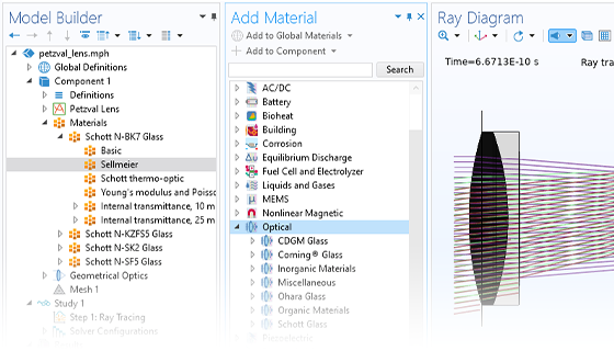
The Ray Optics Module includes a library of essential geometry parts, such as mirrors, lenses, prisms, and aperture stops. Each of these parts is fully parameterized, and many of them include variants with different combinations of input parameters so they can be conveniently modified to fit an optical design.
Objective lenses are used in microscopy systems for a range of scientific research, industrial, and general lab applications. A microscope objective is typically composed of multiple lens elements and located closest to the object. There are so many types of microscope objectives available, choosing the right objective can help you produce good quality images at a reasonable cost. When choosing a microscope objective, we will need to consider a number of factors including conjugate distance, numerical aperture (NA), magnification, working distance, immersion medium, cover glass thickness, and optical aberration corrections. In this article, we will discuss how to choose the right microscope objective.
Infinity-corrected objectives are ideal for research-grade biomedical industrial applications especially when additional components (such as filters, dichroic mirrors, polarizers) are needed in the microscopy system. Adding optical plate components in the infinity space (shown in the Fig.2 labelled as “Parallel Optical Path) between the infinity-corrected objective and tube lens will not introduce spherical aberration, or change the objective’s working distance.
Wave optics
Room 609, 6/F, Global Gateway Tower, No.63 Wing Hong Street, Cheung Sha Wan, Kowloon, Hong Kong +852-54993705 info@shanghai-optics.com
optics期刊
Optical systems can be extremely sensitive to changes in their environment, including high altitudes, space, underwater, and in laser and nuclear facilities. Such optical systems are subjected to structural loads and extreme temperatures. The most accurate way to fully capture these environmental effects is through numerical simulation via a STOP analysis. With the COMSOL Multiphysics® software, you can combine structural, thermal, and optical effects in a single model, so that rays are traced in the thermal-stress-induced deformed geometry while the built-in material models account for temperature-dependence of the refractive index.
The Optical material library includes data for glasses from SCHOTT AG, CDGM Glass Company Ltd., Ohara Corporation, and Corning Inc., along with assorted gases, metals, and polymers. For most of these optical glasses, the refractive index is given as a function of wavelength via a set of optical dispersion coefficients.
Optical simulation
Alpha Industrial Park, Tu Thon Village, Ly Thuong Kiet Commune, Yen My District, Hung Yen Province Vietnam 17721 +84 221-730-8668 rfqvn@shanghai-optics.com
History of optics
When solving for the ray intensity, it can be initialized either by using an expression or loading a photometric data file (specifically an IES file) into the model. Additional predefined ray release features are available to model blackbody radiation and Gaussian beam propagation.
You can also combine the Ray Optics Module with other add-on modules that offer expanded structural and thermal modeling capability — for example, to account for thermal radiation, conjugate heat transfer, hyperelastic materials, and piezoelectricity.
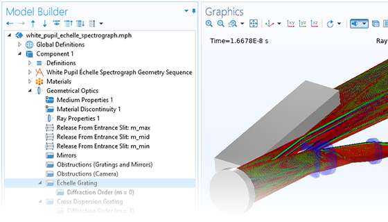
Geometrical optics can be used to model electromagnetic wave propagation in optically large structures. The Geometrical Optics interface includes built-in handling of ray intensity and polarization. The intensity calculation uses a form of Stokes–Mueller calculus that makes it easy to keep track of fully polarized, unpolarized, and partially polarized rays.
The optical aberration corrections determine the optical performance of an objective lens. According to the degrees of the aberration corrections, objective lenses are typically classified into five basic types: Achromat, Plan Achromat, Plan Fluorite (Plan Semi-Apochromat), Plan Apochromat, and Super Apochromat. Choosing an objective with a proper aberration correction level will help you build a microscopy system at a reasonable cost.
The refractive index of each medium can be specified directly or derived from an optical dispersion relation. The dispersion coefficients, such as Sellmeier coefficients, can be loaded from a material database or entered directly into a user-defined material. The refractive index can be complex, wherein the real part determines the speed of light in the medium, while the imaginary part causes ray attenuation or gain.
Objective lenses are used to magnify an image. In addition to numerical aperture, magnification is also an important parameter. The objective magnification typically ranges from 4X to 100X. As the image sensor size or eye observed area is fixed, the field of view of a microscopy system changes with the magnification of the objective lens. Typically a lower magnification objective lens will have a larger field of view and lower resolution, and a higher magnification objective lens will have a smaller field of view and higher resolution. The diameter of the FOV can be calculated by using the following formula: FOV= FN/Mag The field number (FN) in microscopy is defined as the diameter of the area in the image plane that can be observed through the eyepiece or image sensor.
Thermo-optic dispersion coefficients are also available to adjust the refractive index based on temperature. There is also a temperature-dependent Sellmeier dispersion model that combines the temperature and wavelength dependence into a single set of Sellmeier coefficients, which is especially useful for cryogenic materials.
Cosmicray
Rays automatically detect geometry boundaries in their path without the need to specify the order of ray–boundary interactions. When a ray reaches a surface, it can be diffusely or specularly reflected, refracted, or absorbed. You can also assign conditional boundary interactions or randomly choose between two different boundary interactions with a given probability.
At each release position, the rays can be launched in a user-specified direction, or a number of different directions can be sampled from a spherical, hemispherical, conical, or Lambertian distribution.
At boundaries between dielectric media, each incident ray is deterministically split into reflected and refracted rays. Total internal reflection is also detected automatically. If the ray intensity is solved for, it is automatically updated for the reflected and refracted rays according to the Fresnel equations. You can also define thin dielectric layers on material discontinuities, which can be used as filters, antireflective coatings, or dielectric mirrors.
In addition to the refractive index, many of the optical glasses in the Optical material library also provide structural and thermal properties such as density, Young's modulus, Poisson's ratio, coefficient of linear thermal expansion, thermal conductivity, and specific heat capacity. The inclusion of these structural and thermal properties further facilitates coupled STOP analysis. The internal transmittance of the glass is also tabulated as a function of wavelength, so attenuation of light in the medium can also be predicted.
The COMSOL Multiphysics® software also provides the flexibility to show more than just ray paths, with other dedicated plots to view interference fringes and to decompose optical path difference into individual monochromatic aberration terms. You can also plot the intersection points of rays with a plane, sphere, hemisphere, or a more specialized surface.
SO offers a wide range of objective designs, which provide various degrees of optical aberration corrections for supporting different needs, such as achromatic objectives (the cheaper objectives) for laboratory microscope applications and long working distance apochromats (expensive objectives) for biological and scientific research applications. We can help you choose or design a properly corrected objective lens for meeting your application requirements.
Chiefray
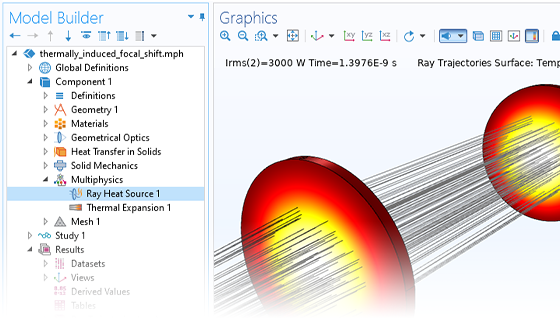
Combining the Ray Optics Module with other modules from the COMSOL product suite enables ray tracing in temperature gradients and deformed geometries, allowing for high-fidelity structural-thermal-optical performance (STOP) analysis within a single simulation environment.
Optics simulation online
NA is commonly expressed as NA = n × sinθa where θa is the maximum 1/2 acceptance angle of the objective, and n is the index of refraction of the immersion medium. The limit of resolution of a microscope objective refers to its ability to distinguish two closely spaced Airy disks. Resolution (r) = λ/(2NA) Where r is resolution (the smallest resolvable distance between two objects), and λ is the imaging wavelength. The higher the NA, the better the objective resolution.
A dry objective is designed to work with the air medium between the specimen and the objective lens, while an immersion objective requires a liquid medium to occupy the space between the object and the front element of the objective for enabling a high NA and high resolution. Figure 4 shows the oil immersion objective, which can collect more light (i.e., have a higher NA) compared to a dry objective.
The Ray Heating interface is used to model electromagnetic wave propagation in optically large systems where the rays and temperature distribution are bidirectionally, or two-way, coupled. The energy lost due to the attenuation of rays in an absorbing medium creates a heat source that is included in the temperature computation.
Usually the working distance (WD) refers the distance from the front lens element of the objective to the observed object when the object is in sharp focus. Objective lenses with long working distance are needed for many scientific research applications such as atom trapping and analyzing fluid samples that require putting an object in a chamber. The resolution of a microscopy system can be significantly affected if the observed object is not placed on the designed object plane, especially for an objective with high NA.
The most common immersion media are air, water, oil, and silicone. Choosing the appropriate objective designed for your immersion medium will result in higher resolution images.
A flexible ray-tracing algorithm allows the rays to propagate through both homogeneous and graded-index (GRIN) media. They can also be monochromatic or polychromatic, where you can specify a distribution of wavelengths or enter a set of discrete values.
With the COMSOL Multiphysics® postprocessing tools, you have the ability to create both visually pleasing and informative simulation results. You can plot rays as lines, tubes, points, and vectors in 2D or 3D, and color the rays by an arbitrary expression that can vary between different rays and even along each ray's path. When solving for ray intensity, you can also plot polarization ellipses along the rays.
For example, you can insert a spherical or conic mirror into the geometry sequence; specify whether the surface is concave or convex; enter its radius of curvature; and then specify the clear diameter, full diameter, and diameter of the flat (if any). These inputs can be adjusted manually or by running a Parametric Sweep study. Additionally, the parts can be oriented with respect to previously inserted parts using built-in work planes, and the parts can automatically create named selections to easily assign boundary conditions to the correct surfaces.


 Ms.Cici
 8618319014500