
Ultraviolet Spectrum - near uv light
Circularpolarization
In many respects, light can be described as a wave phenomenon (→ wave optics). More specifically, light waves are recognized as electromagnetic transverse waves, i.e., with transverse oscillations of the electric and magnetic field.
IR filters (IR is the abbreviation for infrared) can effectively cut the visible rays of light and thus permit transmission of the red region of the light ...
Circularly polarizedlight
Of course, the polarization can have any other direction perpendicular to the beam axis. Note that a rotation of the polarization by 180° does not lead to a physically distinct state.
Coaxial (brightfield) illumination is used to view these targets and produce a bright image. Generally, this type of lighting makes use of a half-mirror.
On the other hand, the polarization state of the laser output can be disturbed e.g. by random (and temperature-dependent) birefringence, such as occurs e.g. in optical fibers (if they are not polarization-maintaining or single-polarization fibers) and also in laser crystals or glasses as a result of thermal effects (→ depolarization loss). If the laser gain is not polarization-dependent, small drifts of the birefringence may lead to large changes in the polarization state, and also a significant variation in the polarization state across the beam profile.
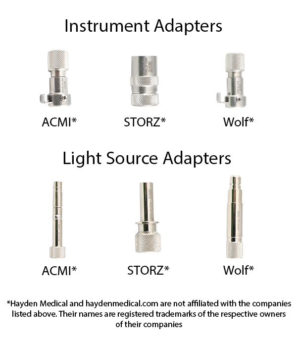
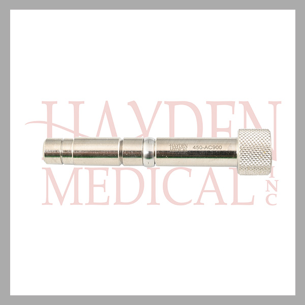
450-678AA2 Fiber Optic Light Cable 10' length, autoclavable, 2mm fiber bundle, (ACMI - Olympus light source / ACMI instrument end plunger style) 450-678AA3 Fiber Optic Light Cable 10' length, autoclavable, 3.5mm fiber bundle, (ACMI - Olympus light source / ACMI instrument end plunger style) 450-678AA5 Fiber Optic Light Cable 10' length, autoclavable, 5mm fiber bundle, (ACMI - Olympus light source / ACMI instrument end plunger style) 450-678AS2 Fiber Optic Light Cable 10' length, autoclavable, 2mm fiber bundle, (ACMI - Olympus light source / Storz - Olympus instrument end) 450-678AS3 Fiber Optic Light Cable 10' length, autoclavable, 3.5mm fiber bundle, (ACMI - Olympus light source / Storz - Olympus instrument end) 450-678AS5 Fiber Optic Light Cable 10' length, autoclavable, 5mm fiber bundle, (ACMI - Olympus light source / Storz - Olympus instrument end) 450-678SA2 Fiber Optic Light Cable 10' length, autoclavable, 2mm fiber bundle, (Storz light source / ACMI instrument end) 450-678SA3 Fiber Optic Light Cable 10' length, autoclavable, 3.5mm fiber bundle, (Storz light source / ACMI instrument end) 450-678SA5 Fiber Optic Light Cable 10' length, autoclavable, 5mm fiber bundle, (Storz light source / ACMI instrument end) 450-678SS2 Fiber Optic Light Cable 10' length, autoclavable, 2mm fiber bundle, (Storz light source / Storz - Olympus instrument end) 450-678SS3 Fiber Optic Light Cable 10' length, autoclavable, 3.5mm fiber bundle, (Storz light source / Storz - Olympus instrument end) 450-678SS5 Fiber Optic Light Cable 10' length, autoclavable, 5mm fiber bundle, (Storz light source / Storz - Olympus instrument end) 450-678SW2 Fiber Optic Light Cable 10' length, autoclavable, 2mm fiber bundle, (Storz light source / Wolf instrument end) 450-678SW3 Fiber Optic Light Cable 10' length, autoclavable, 3.5mm fiber bundle, (Storz light source / Wolf instrument end) 450-678SW5 Fiber Optic Light Cable 10' length, autoclavable, 5mm fiber bundle, (Storz light source / Wolf instrument end) 450-678WA2 Fiber-Optic Light Cable 10' length, autoclavable, 2mm fiber bundle, (Wolf light source / ACMI instrument end) 450-678WA3 Fiber-Optic Light Cable 10' length, autoclavable, 3.5mm fiber bundle, (Wolf light source / ACMI instrument end) 450-678WA5 Fiber-Optic Light Cable 10' length, autoclavable, 5mm fiber bundle, (Wolf light source / ACMI instrument end) 450-678WS2 Fiber-Optic Light Cable 10' length, autoclavable, 2mm fiber bundle, (Wolf light source / Storz - Olympus instrument end) 450-678WS3 Fiber-Optic Light Cable 10' length, autoclavable, 3.5mm fiber bundle, (Wolf light source / Storz - Olympus instrument end) 450-678WS5 Fiber-Optic Light Cable 10' length, autoclavable, 5mm fiber bundle, (Wolf light source / Storz - Olympus instrument end) 450-678WW2 Fiber-Optic Light Cable 10' length, autoclavable, 2mm fiber bundle, (Wolf light source / Wolf instrument end) 450-678WW3 Fiber-Optic Light Cable 10' length, autoclavable, 3.5mm fiber bundle, (Wolf light source / Wolf instrument end) 450-678WW5 Fiber-Optic Light Cable 10' length, autoclavable, 5mm fiber bundle, (Wolf light source / Wolf instrument end) 450-679AA3 Fiber-Optic Light Cable 12' length, autoclavable, 3.5mm fiber bundle, (ACMI - Olympus light source / ACMI instrument end) 450-679AA5 Fiber-Optic Light Cable 12' length, autoclavable, 5mm fiber bundle, (ACMI - Olympus light source / ACMI instrument end) 450-679AS3 Fiber-Optic Light Cable 12' length, autoclavable, 3.5mm fiber bundle, (ACMI - Olympus light source / Storz instrument end) 450-679AS5 Fiber-Optic Light Cable 12' length, autoclavable, 5mm fiber bundle, (ACMI - Olympus light source / Storz instrument end) 450-679SA3 Fiber-Optic Light Cable 12' length, autoclavable, 3.5mm fiber bundle, (Storz light source / ACMI instrument end) 450-679SA5 Fiber-Optic Light Cable 12' length, autoclavable, 5mm fiber bundle, (Storz light source / ACMI instrument end) 450-679SS3 Fiber-Optic Light Cable 12' length, autoclavable, 3.5mm fiber bundle, (Storz light source / Storz instrument end) 450-679SS5 Fiber-Optic Light Cable 12' length, autoclavable, 5mm fiber bundle, (Storz light source / Storz instrument end) 450-679WW3 Fiber-Optic Light Cable 12' length, autoclavable, 3.5mm fiber bundle, (Wolf light source / Wolf instrument end) 450-679WW5 Fiber-Optic Light Cable 12' length, autoclavable, 5mm fiber bundle, (Wolf light source / Wolf instrument end)
If the oscillations of the horizontal and vertical electric field vector do not have the same strengths, one has the case of an elliptical polarization, where the electric field vector, projected to a plane perpendicular to the propagation direction, moves along an ellipse.
In many cases, the output of a laser is a linearly polarized laser beam. Different mechanisms can be responsible for that:
A circular polarization state can mathematically be obtained as a superposition of electric field oscillations in the vertical and horizontal direction, both with equal strength but a relative phase change of 90°. Effectively, this leads to a rapid rotation of the electric field vector – once per optical cycle – which maintains a constant magnitude.
Contactless linear position transducer with magnetostrictive technology. The absence of electrical contact on the cursor eliminates all wear.
We offer a wide range of polarizers and polarization optics for many different uses. Choosing the right polarization optic for your application can be a bewildering task, as we offer a wide range for many different uses.
Electricpolarization
There are also partially polarized states of light. These can be described with Stokes vectors (but not with Jones vectors). Further, one can define a degree of polarization which can be calculated from the Stokes vector and can vary between 0 (unpolarized) and 1 (fully polarized).
There are cases where polychromatic light can be described with a single Jones vector, since all its frequency components have essentially the same polarization state. However, the polarization state is substantially frequency-dependent in other cases.
Shalom EO also offers other optical crystal materials, including: nonlinear crystals, laser crystals, and electric-optical and acousto-optic crystals.
Area-scan light (LTS-NL) Natural Light (LTS-NL) Natural Light View Detail (LTS-SWIR) Short Wavelength Infrared Light (LTS-SWIR) Short Wavelength Infrared Light ...
Here you can submit questions and comments. As far as they get accepted by the author, they will appear above this paragraph together with the author’s answer. The author will decide on acceptance based on certain criteria. Essentially, the issue must be of sufficiently broad interest.
Manufacturer of machine vision lighting systems for medical, food, and beverage applications. Products include co-axial, line, diffuse, bright field, bar, and ...
Everything you need for outdoor lighting. Find information on our efforts to upgrade streetlights to more efficient LED fixtures, how to report outages, and the ...
Note that a very small gain or loss difference for the two polarization directions can be sufficient for obtaining a stable linear polarization, provided that there is no significant coupling of polarization modes within the laser resonator.
Frequently, however, one requires a propagation direction which is not aligned with one of the crystal axes – for example, in the context of critical phase matching. The article on critical phase matching contains an example case for type I phase matching of frequency doubling in LBO, where the pump and second-harmonic beams propagate within the XY plane with an angle ($\varphi$) against the X axis). In this situation, polarization can be either ordinary or extraordinary:
Polarized light is made up of waves that vibrate in a single plane (Fig. 2). There are three types of polarized lights, linearly, circularly, and elliptically ...
Linearly polarized light can be depolarized (made unpolarized) with a polarization scrambler, which applies the mentioned random polarization changes, or at least quasi-random changes.
Sppolarization
polarization中文
Fully polarized states can be associated with points on the so-called Poincaré sphere. Partially polarized states correspond to points inside that sphere; unpolarized light is represented by the point at its center.
A light beam is called unpolarized when the analysis with a polarizer results in 50% of the power to be in each polarization state, regardless of the rotational orientation. Microscopically, this usually means that the polarization state is randomly fluctuating, so that on average no polarization is detected. Note that such fluctuations are not possible for strictly monochromatic light.
The degree of linear polarization is often quantified with the polarization extinction ratio (PER), defined as the ratio of optical powers in the two polarization directions. It is often specified in decibels, and measured by recording the orientation-dependent power transmission of a polarizer. Of course, the extinction ratio of the polarizer itself must be higher than that of the laser beam.
In the previous cases, the direction of the electric field vector was assumed to be constant over the full beam profile. However, there are light beams where that is not the case. For example, there are beams with radial polarization, where the polarization at any point on the beam profile is oriented in the radial direction, i.e., away from the beam axis.
These flexible, fiber-optic cables transmit light from a light source to the surgical field, enhancing visibility and precision.
More info about Creative Light Source. Map. 985 Trade Dr. Ste E. North Las Vegas, NV 89030. Directions. (702) 897-1400. Call Now · Visit Website.
In simple cases, one has a polarization direction along one of the axes of the crystal lattice. One may then call this c polarization, for example, if it is along the crystal's c axis. (Unfortunately, for one type of crystal, there are sometimes different ways of labeling the crystal axes.)
I would have been glad to finally remove a serious mistake, but I believe my equations are correct. They agree with those in various textbooks and e.g. also in Wikipedia. Your argument concerning energy swapping back and forth between the electric and magnetic fields looks somewhat plausible but is not accurate.
Feel free to contact us for assistance. Our experienced staff is only too pleased to help you with the decision process.
20211127 — Unpolarised light would be modelled as an equal mixture of p- and s-polarised light with random, rapidly varying phase differences between them.
When light propagates in a non-isotropic medium, such as a nonlinear crystal, the direction of polarization relative to the crystal axes is relevant. This is not the direction of beam propagation, but rather perpendicular to that.

Politicalpolarization
Your first plot shows the magnetic and electric field in phase – which is wrong. The magnetic field is made from the changing electric field. The two fields swap energy back and forth. Hence the magnetic field is at a maximum when the electric field has the largest rate of change, that is, at zero E field. The magnetic field zeros in strength when the electric field rate of change is zero, at it's peak. These are a simple consequence of Maxwell's Equations and is covered in most any text on E&M. The worst error I have found in years of use of your marvelous resource!
By submitting the information, you give your consent to the potential publication of your inputs on our website according to our rules. (If you later retract your consent, we will delete those inputs.) As your inputs are first reviewed by the author, they may be published with some delay.
Shalom EO offers various birefringent materials, including: MgF2 crystals, LiNbO3 and alpha-BBO crystals, quartz crystals, calcite crystals, and YVO4 crystals. The crystals exhibit excellent properties when used to make waveplates, Glan and Thompson polarizers, and other optical components. Crystal ingots, blanks, and polished and coated optical elements made of birefringent crystals are offered according to your request.
Linearpolarization
A radially polarized laser beam may be generated from a linearly polarized beam with some optical element, but it is also possible to obtain radially polarized emission directly from a laser. The advantage of this approach, applied in a solid-state bulk laser, is that depolarization loss may be avoided [4]. Furthermore, there are applications benefiting from radially polarized light.
Jones vectors can be used only for fully defined polarization states, not for unpolarized or partially polarized beams (see below) having a stochastic nature.
In the simplest case, a light beam is linearly polarized, which means that the electric field oscillates in a certain linear direction perpendicular to the beam axis, and the magnetic field oscillates in a direction which is perpendicular both to the propagation axis and the electric field direction. The direction of polarization is taken to be the direction of the electric field oscillations (i.e., not the magnetic ones). For example, a laser beam propagating in ($z$) direction may have the electric field oscillations in the vertical (($y$)) direction and the magnetic field oscillations in the horizontal (($x$)) direction (see Figure 1); it can be called vertically polarized or ($y$)-polarized. In a different perspective, this is also shown in the second part of Figure 2.
Polarization
Note that radial or azimuthal polarization state requires a zero electric field strength and thus also a vanishing optical intensity on the beam axis; it is not compatible with a Gaussian beam, for example. Radially polarized beams frequently exhibit a kind of donut profile.
The polarization state of light often matters when light hits an optical surface under some angle. A linear polarization state is then denoted as p polarization when the polarization direction lies in the plane spanned by the incoming beam and the reflected beam. The polarization with a direction perpendicular to that is called s polarization. These indications have a German origin: s = senkrecht = perpendicular, p = parallel.
EKSMA Optics has various kinds of birefringent crystal materials including various nonlinear crystals, some of our laser crystals and Raman crystals and polarizing optics crystals.
One distinguishes left and right circular polarization (see Figure 2). For example, left circular polarization means that the electric (and magnetic) field vector rotates in the left direction, seen in the direction of propagation. For an observer looking against the beam, the rotation of course has the opposite direction.
Using our Advertising Package, you can display your logo, further below your product description, and these will been seen by many photonics professionals.
As explained above, a waveplate or other birefringent optical element may rotate the direction of linear polarization, but more generally one will obtain an elliptical polarization state after such an element. True polarization rotation, where a linear polarization state is always maintained (just with variable direction), can occur in the form of optical activity. Some optically active substances such as ordinary sugar (saccharose) can produce substantial rotation angles already within e.g. a few millimeters of propagation length. Optical activity can be accurately measured with polarimeters.
The polarization state of monochromatic light is often described with a Jones vector, having complex electric field amplitudes for ($x$) and ($y$) direction, if propagation occurs in ($z$) direction. That Jones vector may be constant over some area across the beam, or it may vary, for example for a radially polarized beam (see above). The effect of optical elements such as waveplates, polarizers and Faraday rotators can be described with Jones matrices, with which the Jones vectors can be transformed by multiplication. (One assumes a linear relationship between input and output amplitudes.) A whole sequence of such optical elements can be described with a single Jones matrix, which is obtained as the product of the matrices corresponding to the components.
For the mentioned phase-matching scheme, which is denoted as XY oo-e, the pump wave has ordinary polarization, while the second-harmonic wave has extraordinary polarization. There are also cases with type II phase matching, e.g. the scheme XY oe-e, where the pump wave has both an ordinary and an extraordinary polarization component.
There are also azimuthally polarized beams, where the electric field direction at any point is tangential, i.e., perpendicular to a line through the point and the beam axis.
While optical activity usually results from the presence of chiral molecules, with a concentration difference between the two possible enantiometers, it can also be induced by a magnetic field in a substance which is not naturally optically active. That is called the Faraday effect, and is exploited in Faraday rotators and Faraday isolators.
Lux meters or light meters are used to measure levels of light in schools, hospitals, production areas, laboratories, and passageways.
Please do not enter personal data here. (See also our privacy declaration.) If you wish to receive personal feedback or consultancy from the author, please contact him, e.g. via e-mail.


 Ms.Cici
 8618319014500