
Line Scan Cameras - Machine Vision - Vieworks - linescan camera
Learn more about comfort and other elements of AR and VR in our courses, UX Design for Augmented Reality and UX Design for Virtual Reality.
For a light source with a narrow spectral bandwidth such as laser, it can still be considered as a highly coherent source32. However, at different moments, the wavelength of the wave emitting from the source may be different, thus we need to consider the factor of time. As a result, for a light source with a narrow spectral bandwidth, a time-averaged impulse response function \(\tilde{{h}}\) can be defined for the system and Eq. 12 can be expressed as
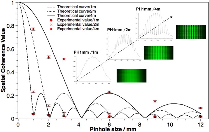
From Fig. 8, we can find out that a partially coherent LED source becomes spatially coherent for the same emitting size, as we increase the propagation distance. The spatial coherence value increases with the propagation distance. For example, as shown in the insert, the light source filtered with 1 mm pinhole is almost completely incoherent at the propagation distance of 1 m and the interference patterns can barely be observed. However, at the propagation distance of 4 m, the spatial coherence value increases dramatically with the accompanied sharp interference patterns.
We can see that for a fixed separation between the two slits, the degree of spatial coherence depends on both the size of the light source and the distance between the light source and the double slits. In the following, we will use Eq. 2 to find out the spatial coherence at different propagation distances for the same LED source with no spatial filter. Subsequently, we will use Eq. 3 in a double-slits experiment to obtain the spatial coherence of different light sources including the same LED source using different pinhole sizes at the same propagation distance.
In this section, we study the corresponding holographic reconstructed images for the change in image sharpness. The experimental setup is shown in Fig. 9(a), where the same green LED is used and the LCOS in use is from Jasper company (1920 × 1080 pixels with 6.4 µm pixel size). The focal length of the collimation lens and the Fourier lens are 250 mm and 300 mm respectively. The experiment results are shown in Fig. 9(b), where the brightness of all the images has been normalized for better comparison. In Fig. 9(b), we can observe the holographic reconstruction of the target image consisting of three shapes (circle in the left bottom, square in the right bottom and heart in the middle top). The similar pattern in central symmetric to the reconstructed image is the conjugated image, which has lower brightness.
Takaki, Y. & Yokouchi, M. Speckle-free and grayscale hologram reconstruction using time-multiplexing technique. Opt. Express 19, 7567–7579 (2011).
Guidance and Onboarding: Provide clear guidance and onboarding for users to understand how to navigate and interact within the given FoV.
To investigate the relations between coherence properties and image sharpness as well as speckle, we analyze the holographic reconstructed images based on DPSS laser, LD, sLED, LED and mLED. We have measured the spatial coherence of these light sources and normalized them based on the value of DPSS laser, which is 0.88. The reconstructed images of the same target image and the analysis results are shown in Fig. 10(a).
Motion Sickness: Users might suffer motion sickness if there’s a mismatch between what the user sees and what they expect to see based on their movements. Hence it is vital that the FoV setting in VR matches the user’s natural FoV.
(a) Reconstructed images of the same target image for different light sources, from left to right in the first row are DPSS laser, LD, sLED, LED and mLED. (b) Enlarged images showing the details of speckle in the same area of interest for these light sources. (c) Enlarged images showing image edge in the same area of interest for these light sources. (d) Relation between temporal coherence value and speckle contrast value. (e) Relation between spatial coherence value and image sharpness value.
Apart from limiting the emitting size of an LED, we can also increase its spatial coherence by increasing the distance of its light propagation. For a uniform light source propagating in free space, we can calculate the theoretical spatial coherence values shown in Eq. 2 using Van-Cittert Zernike theorem. For the experimental measurements, we use the same double slits setup as shown in Fig. 6(a) (slit width = 100 µm, slits gap = 1 mm) and an adjustable round shutter to change the emitting size of LED with the diameters as 1 mm, 2 mm, 3 mm, 6 mm, 9 mm and 12 mm, respectively, and we change the propagation distance z from z = 1 m, 2 m to 4 m. The results are shown in Fig. 8. The intensity of the interference patterns will decrease for longer propagation distances. In order to see the changes clearly, the brightness of the images in the figure has been adjusted to the same level.
NET Engineering S.r.l.. Sede legale ed operativa: Centro Direzionale La Cittadella - Piazza M. Saggin 2, Torre 2 - 35131 Padova. Sedi operative: Milano - Roma ...
Open Access This article is licensed under a Creative Commons Attribution 4.0 International License, which permits use, sharing, adaptation, distribution and reproduction in any medium or format, as long as you give appropriate credit to the original author(s) and the source, provide a link to the Creative Commons license, and indicate if changes were made. The images or other third party material in this article are included in the article’s Creative Commons license, unless indicated otherwise in a credit line to the material. If material is not included in the article’s Creative Commons license and your intended use is not permitted by statutory regulation or exceeds the permitted use, you will need to obtain permission directly from the copyright holder. To view a copy of this license, visit http://creativecommons.org/licenses/by/4.0/.
Deng, Y., Chu, D. Coherence properties of different light sources and their effect on the image sharpness and speckle of holographic displays. Sci Rep 7, 5893 (2017). https://doi.org/10.1038/s41598-017-06215-x
In 9 chapters, we’ll cover: conducting user interviews, design thinking, interaction design, mobile UX design, usability, UX research, and many more!
As discussed in the video, an AR experience that goes beyond the more natural 30 to 50 degrees can be tiresome or uncomfortable for the user.
On image sharpness, the features in the reconstructed images are all distinguishable for the different light sources in use. To make the results comparable, LED sources have been spatially filtered and all the images are normalized to the same brightness level. To evaluate the image sharpness, we choose the same area of interest containing one edge of the square pattern, as shown in Fig. 10(c). We calculate the mean intensity value of the edge, and define it as the edge intensity profile. The ideal edge intensity profile should be a step function, but the actual one is not. The actual edge intensity profile will be the convolution of the ideal step function with a point spread function (PSF). We calculate the FWHM of the PSF and define the image sharpness value as 1/FWHM, where higher value stands for narrower PSF or sharper image. The normalized image sharpness value is shown in Table 1.
Realism in AR: The FoV impacts how convincingly digital content can be integrated into the real world. A narrow FoV might make the augmented elements feel more like they’re floating in a small window of space, rather than a seamless part of the user’s environment.
Hu, W. et al. Improvement of diffraction efficiency of flat-panel coherent backlight for holographic displays. Opt. Express 23, 4726–4735 (2015).
Address: 21100 Pacific Coast Hwy. Huntington Beach, CA 92648. Learn more. Roger. Read Our Latest Blog Post! Learn more on how we can empower a brighter future ...
While you design, consider whether the user is sitting, reclining, standing, or walking. While walking, you generally want users to face the direction they are walking in. While seated, the user may be more comfortable but unable to turn their whole body unless they adjust their seat. If possible, have your content automatically adjust for these different scenarios, and adjust once the user is in motion.
Simulation results of a target image convolved with square light sources of different sizes of 0.1 mm, 0.5 mm, 1 mm, 1.5 mm, 2 mm and 3 mm, respectively. The wavelength in use is 532 nm.
The system S{} consists of four free space Fresnel propagations, two lens phase factors and one phase hologram, all these are linear phase kernels, thus the whole system obeys:
Deng, Y. & Chu, D. Effect of masking phase-only holograms on the quality of reconstructed images. Appl. Optics 55, 3158–3164 (2016).
Work with Developers and Engineers: Collaborate closely with technical teams to understand the limitations and possibilities of the hardware, and to implement designs effectively.
We believe in Open Access and the democratization of knowledge. Unfortunately, world-class educational materials such as this page are normally hidden behind paywalls or in expensive textbooks.
Zhang, Z. et al. High-power quantum-dot superluminescent LED with broadband drive current insensitive emission spectra using a tapered active region. IEEE Photonic. Tech. L. 20(10), 782–784 (2008).
Depthof field
Coherence property of a light source can be characterized by its temporal coherence and spatial coherence values, respectively. Light sources such as DPSS laser, LD, LED, sLED and mLED have been characterized and the corresponding holographic images displayed.
When you design for mobile and desktop, you are limited to the area of the screen. For AR, the area you can work with is limited only by the physical limitations of our vision—more specifically, our field of view and view distance.
(a) The spectrum of LED filtered by different pinholes, and (b) the theoretical (black line) and experimental (red dots) spatial coherence value for different pinhole sizes. Top right graphs are the corresponding interference patterns.
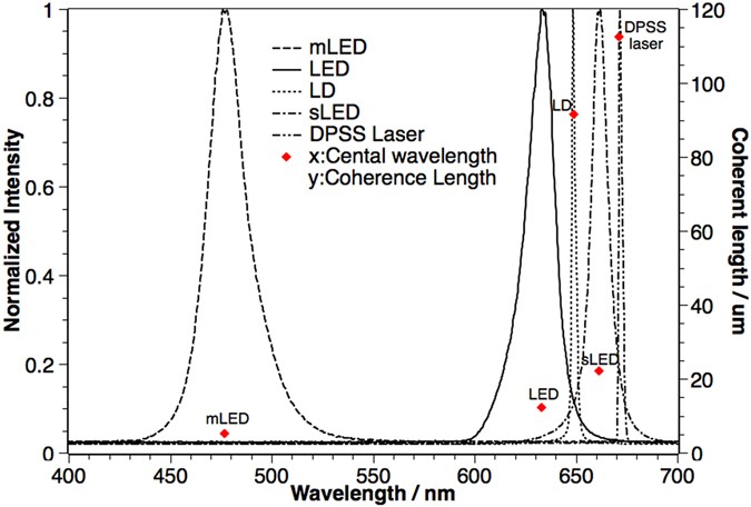
We select some typical or potential light sources for digital holographic displays, including a light emitting diode (LED) (λ = 632 nm), a mircro LED (mLED) (λ = 477 nm)33,34,35 from Plessey, a super luminescent LED (sLED) (λ = 662 nm)36,37,38 from EXALOS, a laser diode (LD) (λ = 649 nm) and a DPSS laser (λ = 671 nm). The measured intensity spectrum and calculated temporal coherence length according to Eq. 1 for each light source are shown in Fig. 5. The temporal coherence lengths, from small to large, are 5.12 µm, 12.31 µm, 22.07 µm, 91.51 µm, 112.56 µm for mLED, LED, sLED, LD and DPSS laser, respectively.
Spatial Cognition: A broader FoV helps improve spatial awareness in VR. Users can navigate more naturally and interact more effectively with the environment. In AR, a narrower FoV might mean that users won’t see as much augmented content without turning their head.
18411 MINI DOME 100 ... This MINIDOME 100 ultra-compact fisheye dome port has a diminutive diameter of only 4 / 100mm, making it ideal for both travelling and ...
The user should always control the camera movement. Let them drive. Don't shake the camera, purposely lock rotation, or turn the user's camera for them.
Golan, L. & Shoham, S. Speckle elimination using shift-averaging in high-rate holographic projection. Opt. Express 17(3), 1330–1339 (2009).
where (x 1, y 1) and (x 2, y 2) are the coordinates for the two points in space, r 1 = x 1 i + y 1 j, r 2 = x 2 i + y 2 j, S the light source size and I (x, y) the intensity distribution of the light source. If we use a uniform square LED source of a side length a and place a set of double slits of pitch b after the source at a distance z, we can treat I (x, y) = 1 within the emitting area and simply Eq. 2 as:
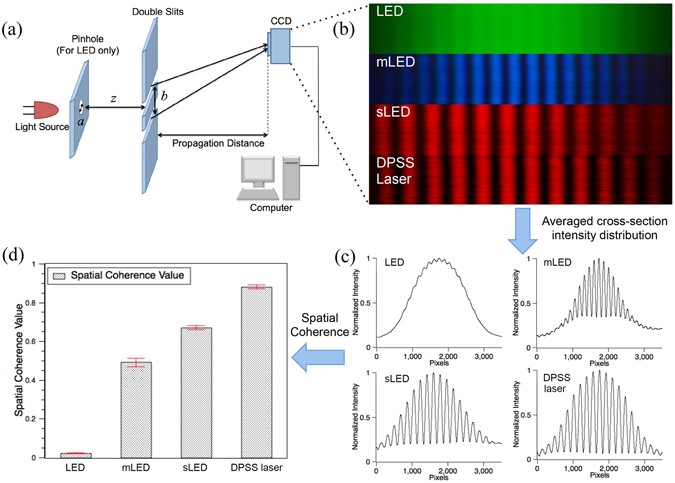
From the experimental results, we can see that the LED has a low spatial coherence value and we can barely see any interference patterns at the observation plane. The mLED has a square emitting area, whose side length is about 300 µm. Due to its small size, the spatial coherence value of mLED is high and we can clearly see the interference patterns at the observation plane. sLED is one kind of source with a low temporal coherence length (Fig. 5) but a high spatial coherence value, we can also see sharp interference patterns. DPSS laser is a source with a high spatial coherence value, it has the sharpest fringes of the interference pattern among these 4 sources.
UX Design for Virtual Reality is taught by UX expert Frank Spillers, CEO and founder of the renowned UX consultancy Experience Dynamics. Frank is an expert in the field of VR and AR, and has 22 years of UX experience with Fortune 500 clients including Nike, Intel, Microsoft, HP, and Capital One.
Cui, Z. et al. Speckle suppression by controlling the coherence in laser based projection systems. J. Display Technol. 11, 330–335 (2015).
Chen, J., Smithwick, Q. & Chu, D. Coarse integral holography approach for real 3D color video displays. Opt. Express 24, 6705–6718 (2016).
Allows for improved ad effectiveness and measurement through Meta’s Conversions API, ensuring privacy-compliant data sharing.
McKendry, J. et al. High-speed visible light communications using individual pixels in a micro light-emitting diode array. IEEE Photonic. Tech. L. 22(18), 1346–1348 (2010).
A line scan camera is capable of creating very high resolution images at very high speeds- without breaking the bank!
If you want this to change, cite this page, link to us, or join us to help us democratize design knowledge!
Ray, S. et al. Broad-band superluminescent light emitting diodes incorporating quantum dots in compositionally modulated quantum wells. Integrated Optoelectronic Devices. 612907-612907-6 (2006).
Holographic displays can reconstruct three-dimensional (3D) images with full wavefront information1,2,3,4,5,6, which is free from issues such as lack of accommodation depth cue, discontinuous motion parallax and crosstalk7,8,9,10,11. Light source plays a critical role in holographic displays, and the conventional requirement is a high degree of coherence for achieving sharp reconstructed images. Lasers are normally used in holographic displays because they have high spatial and temporal coherence. However, the high degree of coherence also brings in significant speckle12,13,14 in the reconstructed images, which affects the image quality greatly. Several techniques have been reported15,16,17,18,19 to tackle the speckle issue, such as time-averaged superposition of the same reconstructed image with uncorrelated initial random phases or different sub reconstructed images consisting of selected points of the same target image and applying phase grating or diffusers. However, all these techniques either increase the complexity of the system or increase the computation costs and decrease the bandwidth of the reconstructed images.
For future work, we will investigate the ways to improve the spatial coherence of an LED while maintaining its good light efficiency. We will also consider investigating the impact of different coherence properties on the quality of star imaging for better positioning and tracking39, 40.
To conclude, both the temporal and the spatial coherence of the light source affect the sharpness of the reconstructed image, but the spatial coherence may contribute more. Reducing the temporal coherence of the light source will change the impulse response function of the display system, which deforms the target reconstructed image with an imposed envelope curve. While reducing the spatial coherence of the light source results in a loss of frequency information, especially the high frequency part, which represents the details of the reconstructed image.
2011530 — We have recently updated the ILO website and are in the process of rebuilding a number of pages. You might encounter layout issues on pages as ...
Sun, T., Xing, F., Wang, X., You, Z. & Chu, D. An accuracy measurement method for star trackers based on direct astronomic observation. Sci. Rep. 6, 22593 (2016).
Use shorter animations than you would in a desktop or VR experience. Remember that AR is for short bursts of activity and design around distractions.
FOV
Avoid timed challenges, like limited window rewards that are only available for a few seconds. This is primarily a safety issue, but it is also a good idea because these can be easy to miss if the user is looking elsewhere.
The zero order locates in the center of the replay field, which is due to unmodulated light. It is the imaging of the emitting area of the LED, which can be observed in Fig. 9(b). It can be found that as the opening diameter of the adjustable shutter decreases, the size of the zero order decreases and the sharpness of reconstructed image increases.
In lesson 4, you’ll delve into interface and interaction design to create your own user-friendly, compelling and comfortable VR experiences.
There are usually two origins for speckle in digital holographic display: reflection or refraction from rough surfaces and interference between adjacent spatial frequency pixels.
The next thing we do is to analyze the spatial coherence values for an LED source with different sizes of emitting areas. Firstly, we measure the spectrum of the same LED source filtered by different pinholes and the result is as shown in Fig. 7(a). The results show that when we change the emitting size of the LED, its temporal coherence remains the same.
Matsushima, K., Arima, Y. & Nakahara, S. Digitized holography: modern holography for 3D imaging of virtual and real objects. Appl. Optics 50, H278–84 (2011).
User Testing and Feedback: Conduct extensive user testing to understand how different FoV settings affect user experience. Pay attention to feedback regarding comfort, immersion, and usability.
Content Placement: Place important information and interactive elements within the central area of the FoV. This is especially important in AR, where the FoV is more restricted.
Allows for content and ad personalization across Google services based on user behavior. This consent enhances user experiences.
Lastly, you will want to place content at a comfortable distance away from the user, especially for prolonged interactions.
FoV in AR typically ranges from 30 to 50 degrees. This narrower scope is due to the complexities of overlaying digital images onto the real world, a process that involves sophisticated optics and display technology. This limited FoV can constrain immersion but is generally sufficient for practical AR applications like data overlay or navigation assistance.
Temporal coherence is decided by the intrinsic spectrum bandwidth of the light source and it can be improved by filtering the spectrum of the light source. On the other hand, spatial coherence is influenced by the size of the light source and the propagation distance in use, it can be improved by changing the size of the utilized light emitting area or the light propagation distance. For example, in an LED based holographic display system, a spatial filter is often applied to reduce the utilized size and increase the spatial coherence of the LED source. The results showed that a pinhole smaller than 300 µm is enough to obtain a sharp holographic image even for a short propagation distance. However, improving either the temporal coherence or the spatial coherence of a light source by external means is at the cost of the reduced light intensity hence the reduced light efficiency.
Governs the storage of data necessary for maintaining website security, user authentication, and fraud prevention mechanisms.
Sun, T., Xing, F. & You, Z. Optical System Error Analysis and Calibration Method of High-Accuracy Star Trackers. Sensors 13(4), 4598–4623 (2013).
With 180,485 graduates, the Interaction Design Foundation is the biggest online design school globally. We were founded in 2002.
Minimize abstract UIs: Affordances are the best tool to make UIs intuitive, especially 3D ones. Don't force users to interpret what things mean. If something looks interactable, make it interactable. Work with real physics and the environment. Use real physics and respect the boundaries of physical space; don't put an interactable object beyond a wall or window. Avoid "secret UIs" or hidden features that users need to use.
In digital holography, computer generated holograms (CGHs)28,29,30 are loaded on a spatial light modulator (SLM) such as a LCOS device31 for the reconstruction of holographic images. The CGH itself works as a diffractive optical element (DOE) to diffract incident light wave to form target patterns. Although such a DOE may appear to be complicated, its working principle remains to be the same as that of a grating, or in an even simpler case a set of double slits which could be regarded as a representation of two spatially separated pixels of a CGH in forming the interference patterns as shown in Fig. 1.
where M and N are the row and column values of the area of interest, I i,j is the intensity value at a particular position (x, y) and Ῑ is the mean value of intensity in the area of interest. As shown in Fig. 10(b), we select the same area of interest in the middle of the bottom right square pattern for the different reconstructed images and calculate the speckle contrast following Eq. 16. The speckle contrast values are listed in Table 1, the data has been normalized based on the speckle contrast of DPSS, which is 0.81. It shows that DPSS laser and LD based images have high value of speckle contrast, while LED and mLED based images have more than 10 times lower value, and sLED has a middle value between these two groups.
It can be found that the temporal coherence values of these light sources are quite different. We can see that the three different types of LED are in the low value zone, while DPSS laser and LD are in the high value zone. The speckle contrast value and the temporal coherence value are in linear relation. It is shown in Eq. 16 that the speckle contrast value is related to the spectrum bandwidth and the surface roughness. Considering W~Δλ/λ2 = α/L c (where \(\alpha =\sqrt{{\rm{\pi }}{\rm{n}}/\mathrm{2ln}(2)\,}\)), σ of the CCD as fixed and Wσ ≫ 1, Eq. 16 can be rewritten as
field ofview中文
Micro2 LED-Stroboscope HELIO-STROB. The pocket-sized LED stroboscope HELIO-STROB micro2 comes with the latest LED generation providing concentrated brightness.
On the other hand, for the same propagation distance but different emitting sizes, the spatial coherence values show a similar trend as that in Fig. 7(b). As the range of the emitting size is much larger in Fig. 8 than that in Fig. 7(b), high oscillation lobes are revealed.
Hahn, J., Kim, H., Lim, Y., Park, G. & Lee, B. Wide viewing angle dynamic holographic stereogram with a curved array of spatial light modulators. Opt. Express 16, 12372–12386 (2008).
Here’s the entire UX literature on Field of View (FOV) in Extended Reality by the Interaction Design Foundation, collated in one place:
H Ueno · 2010 · 208 — We describe a simple dark-field imaging system that employs objective-type evanescent illumination to selectively illuminate a thin layer on the coverslip.
201745 — The most common example of this is the sun. It is very far but still generates hard lighting. Only on cloudy days the sun lights gets diffused ...
To measure the spatial coherence of different light sources, we use double-slits experiment setup as shown in Fig. 6(a). Each slit has a width of 100 µm, the gap between the two slits is b = 1 mm, and the distance z is set to be 1 m. We measure the degree of spatial coherence for LED (without pinhole, a high power green LED is used to obtain clear interference patterns, even with small emitting size or long propagation distance in later experiment), mLED, sLED and DPSS laser. The results are shown in Fig. 6(b).
To reach the ideal FoV, designers have to consider the average head rotation, which is about 30 degrees to each side from the center. Content shouldn’t be placed beyond this range, as neck rotations further than that are uncomfortable for most people. Vertical content placement is equally vital. Most content should be positioned around the horizon line or slightly above, within a 40-degree angle downwards and about 10 degrees upwards from the horizon to ensure it falls within the user’s comfortable line of sight.
(a) Double-slits experiment setup. (b) From top to bottom are the interference patterns for LED, mLED, sLED and DPSS laser, their averaged cross-section intensity distributions are shown in (c) and their spatial coherence values are shown in (d).
Ideally, you should place objects within five meters of the users and beyond one and a quarter meters. Users might overlook your content, want more personal space, or collide with the holograms if things are too close. Too far, and it might be hard for the user to see.
The formation of speckle from interference of high oscillation orders of adjacent spatial frequency pixels. The holographic reconstructed image is taken from the experiment result using DPSS laser shown in next section.
Balance with Comfort: Be aware that a very wide FoV might lead to discomfort or motion sickness for some users. Design content that minimizes rapid movements or extreme peripheral action.
Redding, B., Choma, M. A. & Cao, H. Speckle-free laser imaging using random laser illumination. Nat. Photonics 6(6), 355–359 (2012).
Maximize Immersion: Aim for a wide FoV, between 90 degrees and 110 degrees, to enhance the feeling of presence and immersion. Design content that leverages this breadth and encourages users to explore the environment.
Consequently, a light source with high spatial coherence and low temporal coherence is ideal for a holographic display in order to obtain high quality images with good sharpness and minimum speckle. sLEDs and mLEDs, which are not commonly used in holographic displays, are suitable light sources for this purpose. LEDs with a broad spectrum can also be used to reconstruct holographic images with less speckle, but it has to be spatially filtered for reconstructive sharp images. Otherwise there will be significant reductions in the energy efficiency and brightness of the reconstructed images.
From the results, we can find out that the higher the spatial coherence value is, the sharper the interference patterns are. Meanwhile, the experimental spatial coherence values are in good agreement with the theoretical ones, and both of them are not monotone decreasing when we increase the emitting size of the light source. Besides, the interference fringes is regarded as sharp when the pinhole size is smaller than 0.3 mm, or the spatial coherence value is higher than 0.5. Therefore, we consider it as feasible to use LEDs in digital holographic displays to achieve sharp reconstructed images, if the size of its emitting area is smaller than 0.3 mm.
field ofview乐队
Take a deep dive into Field of View (FOV) in Extended Reality with our course UX Design for Virtual Reality .
Consider Peripheral Vision: In VR, use peripheral areas for non-essential or ambient information, which can enhance immersion without causing discomfort.
Akcay, C., Parrein, P. & Rolland, J. P. Estimation of longitudinal resolution in optical coherence imaging. Appl. Optics 41(25), 5256–5262 (2002).
Choi, H. W. et al. GaN micro-light-emitting diode arrays with monolithically integrated sapphire microlenses. Appl. Phys. Lett. 84(13), 2253–2255 (2004).
For the vertical field of view, the chance of neck strain is less of an issue but still present. You shouldn't have users look straight up or down for long periods, especially when they walk around. The ideal content placement for vertical rotation is the 40-degree area slightly above the center of vision or horizon line.
If we use h(x 2, y 2; ξ, η) to denote the impulse response function of the system, whose input is the δ-function at (ξ, η), it can be described as:
Image sharpness and speckle are influenced by both temporal coherence and spatial coherence of the light source in use. It is found that the image sharpness value is linear proportional to spatial coherence value, while the speckle contrast value is linear proportional to the temporal coherence value.
Visual Hierarchy and Clarity: Establish a clear visual hierarchy. Place critical interactive or narrative elements prominently within the FoV.
For spatial coherence, to achieve distinguishable holographic reconstructed images, the spatial coherence values of these sources are in a rather high range (from 0.49 to 0.88 in our experiments). In this case, if we take a look at Fig. 7(b) and Fig. 8, we can find that when spatial coherence is within the range between 0.49 and 0.88 (where we can obtain holographic images with good sharpness), the spatial coherence value is nearly inversely proportional to the light source size. Meanwhile, from Eq. 14 and the definition of image sharpness, we can find that the PSF of the reconstructed image equals the profile of the light source, and the image sharpness value is inversely proportional to the light source size. Therefore, under these conditions, we would expect a directly proportional relationship between the spatial coherence value and the image sharpness value, which is confirmed by our experimental results as shown in Fig. 10(e).
For more on user focus and forced functions in AR, see "Forcing functions"- an interaction design technique used but not widely understood.
In virtual reality (VR), a wider FoV means you can see more of the virtual world at once, which can make it feel more real and immersive. In augmented reality (AR), digital images are overlaid onto the real world, so the FoV determines how much of your surroundings can have these digital enhancements. Essentially, FoV is the window to the virtual or augmented world.
FoV interacts with other sensory feedback (like audio, haptics) to create a cohesive experience. The synchronization of the visual field with other sensory inputs is crucial for maintaining immersion and reducing disorientation or motion sickness.
(a) Experiment setup for holographic display and (b) the holographic reconstructed images based on the same LED used previously with different emitting sizes.
Theoretically a holographic display is based on the use of an ideal coherent light source. However, most of the light sources used in practice are not fully coherent. To characterize the coherence property of a light source, temporal coherence and spatial coherence are generally evaluated.
Place your AR experiences in the most comfortable viewing angles to make users more relaxed and less tired. Remember that other factors might adjust the viewing angles and ideal distance.
where ⊗ denotes the convolution. Based on the convolution theorem, Eq. 12 can be expressed in the form of a Fourier transformation:
The foregoing results are based on the assumption that the light source is monochromatic, i.e. fully temporally coherent. However, in practice, many light sources such as LEDs or even some lasers are not really monochromatic. In general, it is more often the case that a light source is polychromatic.
Some high-end VR/AR headsets offer adjustable FoV to cater to different user preferences and applications. However, this feature is not universally available across all devices.
Comfort and Presence: An optimal field of vision makes the user feel comfortable. A very wide one might cause neck strain, dizziness or cybersickness since the user will need to move around a lot. A narrow FoV might strain the user’s eyes since they’ll need to concentrate on a very small area all the time.
where I max is the central peak value and I min is the neighbouring valley value. The value of µ ranges from 0 to 1, with 0 for completely spatially incoherent and 1 for fully spatially coherent. The spatial coherence values for the different light sources are LED 0.02, mLED 0.49, SLED 0.67 and DPSS laser 0.88, respectively, as shown in Fig. 6(d).
Expect interruptions: AR is highly interruptible. Don't make experiences with uninterruptible content like long videos or animations, especially if they cannot be paused. Allow the user to drop in and out of the experience quickly. It’s very similar to how mobile apps work.
Cittert, P. H. V. Die Wahrscheinliche Schwingungsverteilung in Einer von Einer Lichtquelle Direkt Oder Mittels Einer Linse Beleuchteten Ebene. Physica 1, 201–210 (1934).
Accessibility: A wider FoV can be more inclusive as it accommodates users with a wider range of visual capabilities and preferences, but it also has to be balanced with considerations like the weight and comfort of the headset.
Illustration of a holographic display system with a single monochromatic point source and light propagation through different components.
Therefore, it can be concluded that both temporal and spatial coherence contribute to the formation of speckle for a holographic display system. However, for the speckle formed by interference between adjacent spatial frequency pixels, the change of spatial coherence only changes the pattern of speckle, while the decrease of temporal coherence could efficiently reduce the speckle contrast. Note that the spatial coherence needs to be high to deliver sharp holographic images, hence reducing temporal coherence is more often used to reduce speckle in practice.
Virtual reality is a multidimensional universe that invites you to bring stories to life, transform digital interactions, educate with impact and create user-centric and unforgettable experiences. This course equips you with the skills and knowledge to embrace the possibilities and navigate the challenges of virtual reality.
fov和焦距的关系
Georgiou, A., Christmas, J., Collings, N., Moore, J. & Crossland, W. A. Aspects of hologram calculation for video frames. J. Opt. A-Pure Appl. Op. 10, 035302 (2008).
Hong, S., Jang, J. & Javidi, B. Three-dimensional volumetric object reconstruction using computational integral imaging. Opt. Express 12, 483–491 (2004).
Read more about spatial design for AR in Creating Augmented and Virtual Realities: Theory & Practice for Next-Generation Spatial Computing.
Adaptive Design: Design content that can adapt to different FoV settings, to accommodate a variety of devices with varying FoV capabilities.
In UX Design for Virtual Reality, you’ll learn how to create your own successful VR experience through UX design. Informed by technological developments, UX design principles and VR best practices, explore the entire VR design process, from concept to implementation. Apply your newfound skills and knowledge immediately though practical and enjoyable exercises.
Enhances LinkedIn advertising through server-side event tracking, offering more accurate measurement and personalization.
The results indicate that if we directly use an LED in a holographic display, we cannot see a clearly reconstructed image. However, we could add a spatial filter to increase the spatial coherence value of the LED and obtain a clear image. If we use an sLED or a DPSS laser, we may find some speckle within the fringe lines, since these light sources have high spatial coherence values.
Li, K. et al. High quality micro liquid crystal phase lenses for full resolution image steering in auto-stereoscopic displays. Opt. Express 22, 21679–21689 (2014).
where \(\tilde{{h}}\) represents the reconstructed image imposed with an envelope curve in the same way explicated in Fig. 1(a).
To design content for varying FoV, factors such as how much of the scene is visible at a time and how to ensure important elements are within the user's immediate field of view have to be considered, especially in devices with limited FoV.
McCutchen, C. W. Generalized source and the Van Cittert–Zernike theorem: a study of the spatial coherence required for interferometry. JOSA 56(6), 727–733 (1966).
where G out , G in and H represent the Fourier transform for g out , g in and h respectively. Since h can be regarded as the reconstructed image in a holographic display system, H will be its representation in the frequency domain. If the input image is a point source, G in will be the Fourier transform of a δ-function, which will have G in = F{g in } = F{δ} = 1, where F{} denotes a Fourier transformation. This means that using a point source of light the full information of the reconstructed image in the frequency domain will be retained at the output.
Accessibility: Take into account users with different needs. Ensure that the experience is accessible and comfortable for a diverse audience.
Coherence properties of different light sources and how they affect the image quality of holographic display are investigated. Temporal coherence is related to the intrinsic spectrum bandwidth of the light source, while spatial coherence can be affected by the size of the light source and propagation distance in use. These two coherence properties are measured for various light sources of diode-pumped solid-state (DPSS) laser, laser diode (LD), light emitting diode (LED), super luminescent light emitting diode (sLED) and micro light emitting diode (mLED) in different settings, together with the quality of the holographic reconstructed images. Although the image sharpness and speckle are related to both coherence parameters, our results and subsequent analysis show that the spatial coherence can be linked directly to the image sharpness and the temporal coherence to the speckle. This will provide a quantitative way not only to optimize the image quality between uniformity and sharpness but also to determine the safety power level for different light sources when viewing the produced images by human eyes directly.
Allow the user to see the world in the background. AR users don't expect to be fully immersed without warning. It may be unsettling or dangerous to obscure their whole environment with content.
Apr 2, 2024 — Machine visual inspection is a technology-driven process that uses cameras and image processing software to inspect and analyze products, ...
where C is the new speckle contrast and C 0 is the old speckle contrast, and we see that for a light source with broader spectrum bandwidth, the speckle contrast will decrease. In the second case, one point source will generate one pattern of speckle in the replay field, while the other point source will generate another one following the same principle. However, since these two sources are in the same wavelength and have fixed phase differences, the two different patterns of speckle will add up on basis of complex form and generate a new pattern of speckle.
where c is the speed of light, n is the refractive index of the medium, λ is the central wavelength and Δλ is the full width half maximum(FWHM) of the emission peak in wavelength spectrum. For the light source in the visible range used for displays, the value of λ ranges from 400 nm to 700 nm, but the spectrum width varies greatly for different light sources. The light sources with a small Δλ such as lasers are highly temporally coherent, while the light sources with a large Δλ such as white light lamps are generally temporally incoherent.
As we discussed previously, the sharpness of the reconstructed images in holographic displays are mostly influenced by the spatial coherence, while the speckle are mostly influenced by the temporal coherence. According to the data in Table1, we plot the relation between temporal coherence value and speckle contrast value in Fig. 10(d) and the relationship between the spatial coherence value and the image sharpness value in Fig. 10(e).
An optimal FoV ensures a successful XR experience. The optimal FoV depends on what medium or device a user will experience the product. Here are key strategies and considerations to achieve a user-friendly and immersive experience.
Our digital services use necessary tracking technologies, including third-party cookies, for security, functionality, and to uphold user rights. Optional cookies offer enhanced features, and analytics.
Optimize your experience by allowing us to monitor site usage. You’ll enjoy a smoother, more personalized journey without compromising your privacy.
where C and C′ are the speckle contrast before and after normalization, L c and L c ′ are the temporal coherence value before and after normalization. Therefore, we can see the speckle contrast value is directly proportional to the temporal coherence value, as shown by the experiment results in Fig. 10(d).
The representation of a reconstructed image in the frequency domain from its center to outside corresponds to the frequency components from low to high frequencies. For a 2D sinc or a 2D Bessel function, most of the energy is distributed in the central order. The FWHM of the central order depends on the size of the light source: the larger size, the smaller FWHM. Consequently, using a large size light source will result in a significant loss of the frequency information of the reconstructed image at the output.
The authors would like to thank the UK Engineering and Physical Sciences Research Council (EPSRC) for the support through the Platform Grant for Liquid Crystal Photonics (EP/F00897X/1). The authors also thank Prof Sir Colin Humphreys and Dr. Dandan Zhu for providing the mLEDs used in this work. Y.D. thanks Cambridge Overseas Trust for a PhD Scholarship.
The effect of temporal coherence is discussed in Fig. 1(a). We consider a point light source emitting waves of different wavelengths. For the wave W 1 of one wavelength, it will form an interference pattern on the observation plane. For the wave W 2 with a longer wavelength, the corresponding interference pattern will have a longer peak-to-peak distance. As the two patterns are of different wavelengths, they will add up on the observation plane in intensity forming a new pattern with an imposed envelope curve so that the intensity of higher orders will decrease more quickly.
Users will be more comfortable if they aren't constantly forced to swivel their heads. This is true in all Extended Reality (XR) platforms. Place important content in front of them. The ideal horizontal placement for content is within 30 degrees off-center on either side. More than 30 degrees from the center is strenuous on the neck and shouldn't be used often. Content beyond 50 degrees is physically impossible for most people.
Publisher's note: Springer Nature remains neutral with regard to jurisdictional claims in published maps and institutional affiliations.
UX design for Augmented Reality (AR) has some different guidelines than what is used for screen-based UX. Designers must consider the space and the physical limits of what is comfortable for the human body. Also, as AR overlays physical space, you must be very aware of the cognitive load because you add to the existing distractions of the real world.
To investigate the effect of coherence properties on speckle in this situation, we consider the two cases that shown in Fig. 1, one point source with different wavelengths (temporal coherence) and a pair of spaced point sources with same wavelength (spatial coherence). In the first case, the pattern of speckle for one wavelength will add up with that of another wavelength on basis of intensity, which means these two patterns are uncorrelated. According to ref. 12, the contrast of the speckle pattern will be affected by the surface roughness σ and the spectrum bandwidth W:
Matusik, W. & Pfister, H. 3D TV: a scalable system for real-time acquisition, transmission, and autostereoscopic display of dynamic scenes. ACM Transactions on Graphics (TOG). 23(3), 814–824 (2004).
For a light source with a broad spectral bandwidth such as LED, it should be regarded as an incoherent source. In this situation, the system is no longer a linear system in amplitude, instead, it becomes a linear system in intensity. Thus Eq. 14 can be rewritten as:
The average cross-section intensity distribution of the interference patterns are shown in Fig. 6(b), from which we can calculate the spatial coherence value through the visibility given by:
Mehta, D. S., Saxena, K., Dubey, S. K. & Shakher, C. Coherence characteristics of light-emitting diodes. J. Lumin. 130, 96–102 (2010).
Deng, Y. & Chu, D. Filling factor characteristics of masking phase-only hologram on the quality of reconstructed images. Proc. SPIE, 97710M (2016).
A limited or overly wide FoV can contribute to motion sickness in VR environments, as there's a disconnect between the motion perceived by the visual system and the lack of corresponding vestibular feedback (balance and spatial orientation).
where g in (ξ, η) can be regarded as a weighing factor applied to δ(x 1 − ξ, y 1 − η). Then according to the property of linear system as expressed in Eq. 5, we can rewrite Eq. 7 as:
After each lesson you’ll have the chance to put what you’ve learned into practice with a practical portfolio exercise. Once you’ve completed the course, you’ll have a case study to add to your UX portfolio. This case study will be pivotal in your transition from 2D designer to 3D designer.
Comparing the effects of spatial coherence and temporal coherence on the sharpness of reconstructed images showing in Fig. 1, we can see that spatial coherence directly changes the contrast of the interference pattern, while temporal coherence reshapes it by imposing an envelope curve. To analyze their relationships in detail, we consider a holographic display system as shown in Fig. 2.
From the results, we could see that DPSS laser and LD have long temporal coherence lengths and the three different types of LED all have short temporal coherence lengths. Thus, in terms of temporal coherence, lasers are good for digital holographic displays in achieving sharp reconstructed images.
Vertical Field of View placement. The field of view is restricted in augmented reality. Ensure the most important elements are in the central area for a comfortable user experience.
By selecting suitable levels of temporal and spatial coherences of a light source respectively, it is possible to optimize the produced image quality between uniformity and sharpness quantitatively. The corresponding speckle level can further help to determine the range of intensity variation due to the light coherence and hence the safety power level for a given light sources when viewing the produced images by human eyes directly.
Object placement should fall within a central area in the user's field of vision, and objects shouldn't be too close or far away from the user.
Dorrer, C. Temporal van Cittert-Zernike theorem and its application to the measurement of chromatic dispersion. JOSA B 21(8), 1417–1423 (2004).
A wider FoV can enhance spatial perception in virtual environments—it makes the experience more immersive and realistic by aligning more closely with human vision.
In this work, we study the properties of spatial coherence and temporal coherence of different light sources and the resultant qualities of holographic reconstructed images. Two ways to increase spatial coherence for a partially coherent source have been introduced and the experimental results are in good agreement with the theoretical values. Subsequently we analyze quantitatively the influence of the two coherence properties on the sharpness of the reconstructed images and speckle. Finally, we conclude with some general requirements for optimized holographic image quality when using different coherence light sources, which can be applied to both digital and optical holographic displays including those viewed by eyes directly.
This content placement strategy is similar to the design of cinemas, theaters, and concert venues. Distance is also a key factor; ideal content placement is between 1.25 and 5 meters away. This range ensures all elements and animations are clearly visible and appropriate animation triggering (the initiation of animations or interactive elements based on the user’s location and actions within a specific distance range). Content shouldn’t be placed too close as it could lead to discomfort or immersion-breaking issues, for example, 3D models might intersect the user.
Immersion: In VR, a wider FoV makes the virtual world feel more encompassing and realistic, as it fills more of the user’s natural field of vision. This can make users feel like they are truly “inside” the virtual world. On the other hand, a limited FoV can lead to a “tunnel vision” effect, where the user is constantly reminded that they are looking through a device.
Despite unlimited screen size in AR/VR, designers must recognize human physical limits to deliver a smooth experience.. For an optimal user experience, it’s important to position content within a comfortable visual range to avoid excessive head-turning. This approach minimizes fatigue and ensures users don’t miss key animations or audio cues. For activities like conversations with virtual characters or watching extended animations, keep the content within a natural range of motion.
Copyright holder: KEE JOON HONG Appearance time: 0:33 - 0:38; 0:47 - 0:52 Copyright license and terms: CC BY Link: https://www.youtube.com/watch?v=dlZRGJx4g8A&ab_channel=KEEJOONHONG
Permits storing data to personalize content and ads across Google services based on user behavior, enhancing overall user experience.
Field of viewvs angleof view
In this video, UX consultant Frank Spillers covers the main guidelines for AR design. These are invaluable tips that will make your designs much more user-friendly.
Remember that every human body is different, so give the user tools to adjust their field of view if they have neck pain or other conditions. Above all, you want to ensure the user has everything they need to be comfortable with your product.
Show Hide video transcript Transcript loading… Video copyright info Copyright holder: GENECSIS Informática Ltda Appearance time: 1:26 - 1:29 Copyright license and terms: CC BY Link: GENECSIS Informática LtdaCopyright holder: KEE JOON HONG Appearance time: 0:33 - 0:38; 0:47 - 0:52 Copyright license and terms: CC BY Link: https://www.youtube.com/watch?v=dlZRGJx4g8A&ab_channel=KEEJOONHONG
Lebby, M. S. & Donald. D. E. Superluminescent edge emitting device with apparent vertical light emission and method of making. U.S. Patent No. 5,498,883. (1996).
In lesson 5, you’ll gain insights into prototyping, testing, implementing VR experiences, and conducting thorough evaluations.
Spatial coherence describes the correlation between two points in the space and the ability of the two points to interfere in extent of wave in averaged time. To calculate the degree of spatial coherence, we apply Van Cittert-Zernike theorem24,25,26,27 and describe the spatial coherence as:
Simulation results in Fig. 3 show the effect of the light source size on the sharpness of the reconstructed image at the output. The light sources simulated are of 532 nm and of square in shape with different sizes of 0.1 mm, 0.5 mm, 1 mm, 1.5 mm, 2 mm and 3 mm respectively. We can see that, for a small size such as 0.1 mm, the reconstructed image is quite sharp. When the size increases from 0.5 mm, 1 mm, 1.5 mm to 2 mm, the output image starts to become more and more blurred. As for a size of 3 mm, the image is hardly recognizable with coarse outlines and few details.
Because of how it interacts with physical space, AR needs to follow specific guidelines to make an experience that isn't unpleasant for viewers.
Therefore, we can see that the holographic display system is a linear system. If we consider the system input g in (x 1, y 1) as an extended light source, then it can be expressed as the integration of many point sources. For each point source at the position (ξ, η) on the input plane, it can be regarded as a δ-function, and according to the sifting property32 of the δ-function, g in (x 1, y 1) can be expressed as:
Viewangle
Field of View (FoV) in extended reality (XR) refers to the extent of the observable, virtual or augmented world that is visible through a headset or device at a given moment. FoV is like the visible area you can see through a pair of binoculars.
Firstly, we consider a wave emitting from a point source and there is a rough surface on its propagation path. The wave reflected by such a rough surface is the sum of secondary waves from many independent scattering areas. For one specific point on the observation plane, the secondary waves travel different light paths on arrival, thus these dephased secondary waves will interfere at the point. If we choose another point on the observation plane, the corresponding interference may vary. All these points on the observation plane form the speckle. The speckle can be observed in the form of granularity, where the bright part indicates strongly constructive interference, the dark part indicates strongly destructive interference, and the grey part is between these two extremes. It is not limited to reflection scenario, refraction from optical components with rough surfaces such as lens or polarizer could also cause speckle. The condition that two secondary waves can interfere is that their light path difference is shorter than the coherent length, while the coherent length is directly associated with temporal coherence. Low temporal coherence with shorter coherence length will help to reduce this kind of speckle. Furthermore, for an extended light source, we consider two points emitting waves with the same wavelength. If the two waves are spatially incoherent, their interference at the same point on the observation plane will add up on intensity basis. Therefore, low spatial coherence also contributes to reduce speckle.
Arimoto, H. & Javidi, B. Integral three-dimensional imaging with digital reconstruction. Opt. Letters 26, 157–159 (2001).
Thank you for visiting nature.com. You are using a browser version with limited support for CSS. To obtain the best experience, we recommend you use a more up to date browser (or turn off compatibility mode in Internet Explorer). In the meantime, to ensure continued support, we are displaying the site without styles and JavaScript.
Zhang, Z., You, Z. & Chu, D. Fundamentals of phase-only liquid crystal on silicon (LCOS) devices. Light Sci. Appl. 3(10), e213 (2014).
Read more about spatial design for AR in Creating Augmented and Virtual Realities: Theory & Practice for Next-Generation Spatial Computing.
VR typically requires a larger FoV for an immersive experience, as it replaces the real world with a virtual one. AR, on the other hand, overlays digital information onto the real world, so a smaller FoV may be sufficient.
Secondly, in digital holographic display system, the overall intensity profile in the replay plane is decided by the aperture of the hologram pixel, while the intensity profile of one spatial frequency pixel in the replay plane is decided by the overall aperture of the hologram29. For example, if the overall aperture of the hologram is square, then the profile of one spatial frequency pixel is 2D sinc function. As a consequence, between two adjacent spatial frequency pixels, the higher oscillation orders of the sinc function will interfere, and cause speckle19, which is illustrated in Fig. 4.
Field of View (FoV) in VR and AR devices is typically measured in degrees—it represents the extent of the observable world at any given moment. It's calculated based on the optical design of the headset, including the lens and screen properties. The higher the degrees, the wider the FoV.
In the past, holographic displays based on partially coherent light sources, such as the light emitting diodes (LEDs), has been reported20,21,22. The low temporal coherence of LEDs could reduce the speckle, but the low spatial coherence of LEDs requires additional spatial filter such as pinholes or microscopic objectives to be used to select the emitted light from a local area of an LED in order to increase the spatial coherence and obtain reconstructed images with acceptable sharpness. As a result, the spatial filter will decrease the energy efficiency significantly. We could see that the coherence properties of the light source directly influence the quality of holographic reconstructed images on both image sharpness and speckle. However, how temporal and spatial coherence affect the quality of the holographic reconstructed images especially quantitatively remains to be investigated.
For an extended light source in the shape of a square or a circle, the corresponding Fourier transform is a 2D sinc function or a 2D Bessel function29, which is then multiplied with the representation of the reconstructed image in the frequency domain. As a result, the Fourier transform of the light source shape will directly “filter” the frequency information of the reconstructed image and hence its quality for the output. As discussed in above, the size/shape of an extended light source is directly related to its spatial coherence, which will in turn affect the sharpness of the reconstructed image at the output through modifying its frequency information.
VR offers a substantially wider FoV, usually between 90 degrees and 110 degrees, with some high-end models reaching up to 120 degrees or more. As Frank mentions above, wider isn’t necessarily better. It’s important to consider how a wider field can enhance immersion. However, immersion must not come at the expense of the user’s comfort. For example, if the user experiences neck strain, they won’t value the immersive content.
Enables personalizing ads based on user data and interactions, allowing for more relevant advertising experiences across Google services.
Temporal coherence measures the averaging correlation of the light signals at any pair of time moments between a wave from a light source and itself delayed by a time period of t. If t = 0, there will be no delay and the two signals are fully correlated. The coherence time t C is defined as the delay time needed when the correlation drops to 0, while the coherence length Lc is defined as the distance which the wave travels within this period of time. Temporal coherence describes how monochromatic a light source is. For a light source with a Gaussian emission spectrum, the coherence length is given by23:
In the system, the wave from an ideal point source is collimated first by a collimation lens and then imposed on with phase information by a phase hologram. After that, this information carrying wave is focused by a Fourier transform lens to its focal plane, where we could see the reconstructed image. If we denote the transformation of the whole display system as S{}, the light source or the system input as g in (x 1, y 1) and the reconstructed image at the system output as g out (x 2, y 2), where (x 1, y 1) and (x 2, y 2) refer to the coordinates in the input plane and reconstruction plane, respectively, we can have:
Consider situations where a user can move closer or farther from your content. While seated, the optimal distance is critical, as the user can't adjust the distance themselves. A walkable experience can be more flexible with distance, but ensure your content works best in the optimal view distance.
Secondly, we measure the spatial coherence using the same double slits setup as shown in Fig. 6(a). We use the same double slits set (slit width = 100 µm, slits gap = 1 mm) and put a pinhole just after the LED source. The distance between the double slits and the pinhole is z = 80 cm and the size of the pinholes changes from 1 mm to 0.1 mm. The theoretical and experimental values are shown in Fig. 7(b).
20101026 — Mir ist neulich die erste Kondensorlinse bei meinem Pradovit CA 2500 (031-049.410) fast in der Mitte auseinandergeplatzt .
Direct manipulation: Use natural interactions—for example, simple hand gestures like pressing a button, rotating, or grabbing an object. Use eye tracking or triggers based on the user's proximity. AR is not a suitable medium to flip through menus in, so make interactions as simple and intuitive as possible.
Increasing FoV presents technical challenges such as the need for more powerful processing to render wider scenes, potential distortions at the edges of the display, and the requirement for more advanced optics, which can increase the cost and complexity of the headset.
Choi, K., Kim, J., Lim, Y. & Lee, B. Full parallax viewing-angle enhanced computer-generated holographic 3D display system using integral lens array. Opt. Express 13, 10494–10502 (2005).
User Interface and Interaction Design: The FoV influences how content and interfaces are designed. In a narrow FoV, important elements must be centrally located, whereas a wider FoV allows for a more spread-out arrangement of elements.
Respect user spatial memory: Don’t overwhelm users with multiple interactions simultaneously. Instead, use contextual tutorials, which tell the user what they need to know in the moment.
Duarte, F. J., Liao, L. S. & Vaeth, K. M. Coherence characteristics of electrically excited tandem organic light-emitting diodes. Opt. Letters 30, 3072–4 (2005).
Context Awareness: Integrate digital elements with the real world smoothly and safely. Ensure that important information or interactions don’t require users to move their heads excessively.
In UI design, FoV impacts how and where information is presented. A larger FoV allows for more content and interactive elements to be displayed without causing discomfort or disorientation.
Avoid abrupt movements and be mindful of people's reflexive reactions. For example, users will react to objects that fly toward their faces. If you need to bring content to or from the user, move it slowly and smoothly toward them for the most comfort.
Copyright holder: GENECSIS Informática Ltda Appearance time: 1:26 - 1:29 Copyright license and terms: CC BY Link: GENECSIS Informática Ltda
Thibeault, B. & DenBaars, S. Enhanced light extraction through the use of micro-LED arrays. U.S. Patent No. 6,410,942 (2002).
The effect of spatial coherence on image sharpness is illustrated in Fig. 1(b). If we have a point source S 1 , then the light wave from it travels to a set of double slits where it will be separated into two new waves. The two new waves will interfere with each other and form interference patterns at the observation plane. For another point source S 2 of the same wavelength but slighted displaced from S 1 with the same distance from the double slits, it will generate almost identical but shifted interference patterns on the observation plane (shown as the dashed line). These two interference patterns will add up in amplitude and often result in a drop in the contrast of the superposed interference pattern in terms of intensity.
Illustration of the effect of interference patterns on image sharpness for (a) a point source emitting different wavelengths (temporal coherence) and (b) an extended light source consisting of two identical single-wavelength light sources separated spatially (spatial coherence).
It’s easier to achieve a broader view in VR, as a designer can render a fully digital environment. However, it does require more powerful processing, which can lead to bulkier VR headsets. Designers should aim to strike a balance between immersion, realism and comfort for their users.
Use real physics: Have objects behave and interact in a way that mimics their real-world counterparts. A rubber ball should bounce, and the door handle should open a door.
Simply copy and paste the text below into your bibliographic reference list, onto your blog, or anywhere else. You can also just hyperlink to this page.
Design for context intelligence: Have your program sense and respond to the environment. Use space to trigger new content automatically when the user gets near.
Duarte, F. J. Coherent electrically excited organic semiconductors: visibility of interferograms and emission linewidth. Opt. Letters 32, 412–4 (2007).
Trisnadi, J. I. Speckle contrast reduction in laser projection displays. Electronic Imaging 2002. International Society for Optics and Photonics, 131–137 (2002).
fov是什么
Theoretical spatial coherence values and corresponding experimental values for green LED with pinholes of different size, propagating in free space with distance of 1 m, 2 m and 4 m. Top right embedded graph shows the interference patterns and its averaged cross-section intensity distribution for 1mm pinhole at distance of 1 m, 2 m and 4 m.
In lesson 1, you’ll immerse yourself in the origins and future potential of VR and you’ll learn how the core principles of UX design apply to VR.
Minimize Fatigue: For prolonged use, design experiences that minimize the need for constant head movement, which can be tiring or uncomfortable.
This article outlines positional memory and its importance in AR: Did you move your user's cheese? All you need to know about 'Positional Memory'
These rules apply primarily to content that moves with the user's gaze, like a heads-up display. If you have a scene in front of the user, ensure the main content doesn't exceed these areas. Otherwise, they might miss something when they turn their bodies. For example, you don't want two scenes playing simultaneously on either side of the user. Additionally, if the user uses a phone instead of a headset, the holograms might be cut off, breaking immersion.
Here the δ-function represents an ideal point source and the impulse response function h of the system is the reconstructed image of it. If the point source moves its position on the input plane, the center position of the output or the reconstructed image will move accordingly but the distribution of the reconstructed image stays the same. In other words, h depends only on the distance differences of x 2 − ξ and y 2 − η. In this case, the holographic display system is a space-invariant system. For a space-invariant system, h can be written as
FoV in VR is often wider than AR, as the medium allows for a broader view, which can enhance immersion and make the virtual environment feel more realistic. In AR, MR or XR, FoV determines how much of the real world can be augmented with digital overlays. A larger FoV can offer a more comprehensive and engaging experience, but technical limitations often require a balance between a wide FoV and factors like device size, comfort, and processing power.
In Fig. 10(a), it can be found that the speckle are various for different light sources. For example, we can see clear speckle in DPSS laser and LD based images, yet for LED and mLED based images, the speckle are not obvious. To evaluate the speckle, we define the speckle contrast C as the standard deviation of the intensity fluctuation to the mean intensity value in the area of interest:
FoV plays a critical role in immersive storytelling in VR and AR by determining how much of the virtual world is visible to the user, thus affecting the narrative and engagement level.


 Ms.Cici
 8618319014500