
CIE | International Commission on Illumination / Comission ... - light illumination
The OSL2 comes with a pre-installed OSL2B bulb that has an integrated hot mirror that blocks the majority of the IR light and has a typical wavelength range of 400 - 1600 nm. The OSL2IR comes with the OSL2BIR bulb which provides enhanced output in the near-IR due to the aluminum-coated reflector and lack of integrated hot mirror; it has a typical wavelength range of 400 - 1750 nm. Please see the Specs tab for more details.
Because additive processes have the greatest gamut when the primaries are red, green, and blue, it is reasonable to expect that the greatest gamut in subtractive processes will be achieved when the primaries are, respectively, red-absorbing, green-absorbing, and blue-absorbing. The colour of an image that absorbs red light while transmitting all other radiations is blue-green, often called cyan. An image that absorbs only green light transmits both blue light and red light, and its colour is magenta. The blue-absorbing image transmits only green light and red light, and its colour is yellow. Hence, the subtractive primaries are cyan, magenta, and yellow (see figure, right).
Newton demonstrated that colour is a quality of light. To understand colour, therefore, it is necessary to know something about light. As a form of electromagnetic radiation, light has properties in common with both waves and particles. It can be thought of as a stream of minute energy packets radiated at varying frequencies in a wave motion. Any given beam of light has specific values of frequency, wavelength, and energy associated with it. Frequency, which is the number of waves passing a fixed point in space in a unit of time, is commonly expressed in units of hertz (1 Hz = 1 cycle per second). Wavelength is the distance between corresponding points of two consecutive waves and is often expressed in units of metres—for instance, nanometres (1 nm = 10−9 metre). The energy of a light beam can be compared to that possessed by a small particle moving at the velocity of light, except that no particle having a rest mass could move at such a velocity. The name photon, used for the smallest quantity of light of any given wavelength, is meant to encompass this duality, including both the wave and particle characteristics inherent in wave mechanics and quantum mechanics. The energy of a photon is often expressed in units of electron volts (1 eV = 1.602 × 10⁻¹² erg); it is directly proportional to frequency and inversely proportional to wavelength.
These light sources have a built-in protection mechanism to prevent the unit from overheating and to turn off the lamp when the access door is opened. The LED indicator on the front panel is green during normal operation. If the unit overheats, power to the lamp is cut off and the LED turns red. If the access door is opened during normal operation, power to the lamp and the LED are cut off.
Thorlabs’ FRI61F50 Fiber Ring Illuminator has a 915 mm (36.02") long fiber bundle that couples light from our OSL2 and OSL2IR Light Sources into a Ø55 mm ring illuminator composed of five concentric fiber rings. The illuminator easily mounts onto most standard upright microscopes, such as the one shown in Figure G3.1. It is secured using three thumbscrews, each of which is nylon tipped to produce adequate holding friction while preventing scratching or marring of the microscope. The fiber ring slips around any objective housing with a diameter of 60 mm or less.
Fiber Opticilluminator surgery
No concepts in the field of colour have traditionally been more confused than those just discussed. This confusion can be traced to two prevalent misnomers: the subtractive primary cyan, which is properly a blue-green, is commonly called blue; and the subtractive primary magenta is commonly called red. In these terms, the subtractive primaries become red, yellow, and blue; and those whose experience is confined for the most part to subtractive mixtures have good cause to wonder why the physicist insists on regarding red, green, and blue as the primary colours. The confusion is at once resolved when it is realized that red, green, and blue are selected as additive primaries because they provide the greatest colour gamut in mixtures. For the same reason, the subtractive primaries are, respectively, red-absorbing (cyan), green-absorbing (magenta), and blue-absorbing (yellow).
Four replacement bulbs for use with the light sources are available below, along with their emission spectra. The OSL2B and OSL1B bulbs are identical to the bulbs used in the OSL2 and the former OSL1 light sources, respectively, and emit in the visible spectrum. The OSL2B2 bulb also emits in the visible spectrum and provides greater power output at the expense of bulb lifetime. Lastly, the OSL2BIR bulb is used in the OSL2IR light source and offers enhanced emission in the near infrared through the use of an aluminum-coated reflector. Further details on compatible bulbs are also provided on the Specs tab.
The fiber ring illuminator can be attached to the OSL2 or OSL2IR using the included adapter. The two nylon-tipped setscrews can be tightened using the included 1/16" hex key. Our AD16F adapter is available as a replacement.
A 91 cm (36") long fiber bundle with a Ø6.4 mm (Ø0.25") effective core is included with the OSL2 and OSL2IR light sources. To adapt the fiber bundle output to an optomechanical setup, we recommend using our AD8F mounting adapter (see Figure 1.2), which provides external SM1 (1.035"-40) threading for easy integration with any of our SM1-threaded components. In particular, this adapter can be used to connect the OSL2 or OSL2IR to a Cerna® microscope for both epi-illumination and trans-illumination; see the Use with Cerna tab for details.
Additive mixing occurs when beams of light are combined. The colour circle, first devised by Newton, is still widely used for purposes of colour design and is also useful when the qualitative behaviour of mixing beams of light is considered. Newton’s colour circle combines the spectral colours red, orange, yellow, green, cyan, indigo, and blue-violet with the nonspectral colour magenta (a mixture of blue-violet and red light beams), as shown in the figure. White is at the centre and is produced by mixing light beams of approximately equal intensities of complementary colours (colours that are diametrically opposed on the colour circle), such as yellow and blue-violet, green and magenta, or cyan and red. Intermediate colours can be produced by mixing light beams, so mixing red and yellow gives orange, red and blue-violet gives magenta, and so on.
The three additive primary colours are red, green, and blue; this means that, by additively mixing the colours red, green, and blue in varying amounts, almost all other colours can be produced, and, when the three primaries are added together in equal amounts, white is produced.
Fiber Optic Light SourceIlluminator
Gooseneck Single-Output Fiber BundleThe OSL2RFB Gooseneck Single-Output Fiber Bundle has the same fiber configuration as the bundle included with the OSL2 and OSL2IR, but has a gooseneck jacket for stability and easy manual positioning. The gooseneck jacket allows the bundle to maintain its position once it has been set.
Additive mixing can be demonstrated physically by using three slide projectors fitted with filters so that one projector shines a beam of saturated red light onto a white screen, another a beam of saturated blue light, and the third a beam of saturated green light. Additive mixing occurs where the beams overlap (and thus are added together), as shown in the figure (left). Where red and green beams overlap, yellow is produced. If more red light is added or if the intensity of the green light is decreased, the light mixture becomes orange. Similarly, if there is more green light than red light, a yellow-green is produced. The RGB colour model, one of the three main colour models, is an additive model used in digital devices and light-based media to create a gamut of colours from just red, green, and blue.
The OSL2 is compatible with a Cerna microscope via the single-cube epi-illuminator module (Item # WFA2001), which contains anti-reflective (AR)-coated optics with <0.5% average reflectance per surface over the 350 - 700 nm wavelength range. The halogen lamp fiber bundle and epi-illuminator module are connected together by an SM1-threaded (1.035"-40) adapter (Item # AD8F). First thread the adapter onto the epi-illuminator module, then secure the fiber bundle with the nylon-tipped setscrews on the adapter [1/16" (1.5 mm) hex]. The epi-illuminator module accepts an uncollimated light source, so no collimation package is necessary.
Our fiber ring illuminator provides lighting very nearly aligned to the optical axis of the microscope that is shadow-free and uniform across the sample plane and throughout the entire working distance (WD) range. The use of 5 fiber rings increases the light intensity and WD range compared to illumination from a single fiber ring.
Subtractive colour mixing involves the absorption and selective transmission or reflection of light. It occurs when colorants (such as pigments or dyes) are mixed or when several coloured filters are inserted into a single beam of white light. For example, if a projector is fitted with a deep red filter, the filter will transmit red light and absorb other colours. If the projector is fitted with a strong green filter, red light will be absorbed and only green light transmitted. If, therefore, the projector is fitted with both red and green filters, all colours will be absorbed and no light transmitted, resulting in black. Similarly, a yellow pigment absorbs blue and violet light while reflecting yellow, green, and red light (the green and red additively combining to produce more yellow). Blue pigment absorbs primarily yellow, orange, and red light. If the yellow and blue pigments are mixed, green will be produced since it is the only spectral component that is not strongly absorbed by either pigment.
If a higher color temperature is desired, our color-balancing filters can be used to attenuate red light from the OSL2 light source while passing blue light. This results in a beam with a higher color temperature and lower total power.
Clicking the icon in Table G3.2 will open a window that contains additional specifications, performance data, and drawings.
Figure G4.4 illustrates one way to filter the output light from the OSL2 lamp using a mounted Ø25.0 mm filter. For details on alternate configurations using unmounted Ø12.5 mm or Ø25.0 mm filters, please click the photo.
The FRI61F50 has a WD range of 50 - 170 mm. Using the illuminator at distances greater than 170 mm will result in low-intensity, even illumination, which may be acceptable depending on the application.
To install the replacement bulb in the former OSL1 source, simply loosen the two fasteners on the front panel of the unit, slide out the bulb assembly, and remove the old bulb. Details are available in Chapter 4 of the OSL1 manual, available as a PDF here. The OSL1B bulb can also be installed in our OSL2 or OSL2IR light source by following the installation instructions in Chapter 5 of the OSL2 manual or OSL2IR manual.
To assemble the cage system for the OSL2, first mount the lens onto a SM1 (1.035"-40) threaded 30 mm cage plate (Item # CP33(/M)) using the included retaining rings (Item # SM1RR). The other cage plate secures the Ø8 mm to SM1 adapter (Item # AD8F); utilize an additional retaining ring to set the adapter at a particular position. Attach the cage rods (Item # ER3-P4) to the trans-illumination module by removing the dust cover on the side of the module with a 1.5 mm hex, then locking the cage rods into place using the exposed side-locking 4-40 setscrews (0.05" hex). Once the cage rods are secure, slide the cage plate with the optic onto the rods so that the convex side of the lens faces the trans-illumination module. This is then followed by the cage plate with the AD8F adapter. The cage plates are secured to the cage rods using side-locking 4-40 setscrews. Once the assembly is secure, mount the tip of the fiber bundle onto the end of the collimation package using two 6-32 setscrews [1/16" (1.5 mm) hex]. See Figures 3.3, 3.4, and 3.5 for a visual depiction of this assembly.
The fiber illuminator's output port also has internal, 3.5 mm deep SM1 threads. The unit is shipped with a fiber bundle adapter installed in these threads. By removing the fiber bundle mounting adapter from the output port, standard fiber connector adapters (sold below) and other SM1-threaded components can be attached to the light source.
Colours of the spectrum are called chromatic colours; there are also nonchromatic colours such as the browns, magentas, and pinks. The term achromatic colours is sometimes applied to the black-gray-white sequence. According to some estimates, the eye can distinguish some 10 million colours, all of which derive from two types of light mixture: additive and subtractive. As the names imply, additive mixture involves the addition of spectral components, and subtractive mixture concerns the subtraction or absorption of parts of the spectrum.
The OSL1-SMA adapter inserts into the front panel of the former OSL1 unit and is secured by a thumbscrew. It is compatible with SMA905- and SMA906-style connectors.
Thorlabs offers fiber bundles designed to be used with the OSL2 and OSL2IR Light Sources sold above. These cables have fiber tips with Ø7.9 mm (Ø0.31") outer dimensions, enabling them to be used in place of the fiber bundle included with the OSL2 and OSL2IR.
Below is a selection guide for all of our white-light, broadband, lamp-based light sources. In addition to these sources, Thorlabs also offers unmounted white-light LEDs, white-light mounted LEDs, white-light fiber-coupled LEDs, and high-powered, white-light Solis® LEDs.
Gooseneck Y-BundleThe OSL2YFB Gooseneck Y-Bundle (Bifurcated) Cable splits the output of the light source into two independently positionable beams, allowing larger work areas to be illuminated. Unlike the fiber bundle included with the OSL2 and OSL2IR, each leg of this bifurcated cable has a gooseneck jacket for easy manual positioning.
Thorlabs offers three different replacement bulb for the OSL2 and OSL2IR Light Sources. The OSL2B is identical to the original bulb that comes with the OSL2 source, and the OSL2B2 is a high-power variant of the OSL2B bulb. The OSL2BIR bulb is identical to the original bulb that comes with the OSL2IR. The OSL2B and OSL2B2 bulbs each have an integrated hot mirror that blocks most of the IR light. In contrast, the OSL2BIR bulb provides enhanced output in the near-IR due to the aluminum-coated reflector and lack of integrated hot mirror. Figure G6.2 compares the spectra and power of these bulbs. To view a spectrum and raw data for each individual bulb, click on the graph icons in Table G6.3.
Because the WFA1000 and WFA1100 trans-illumination modules need a Ø1" collimated light source secured to a 30 mm cage system to provide even illumination, the emitted beam from the OSL2 must be collimated by a plano-convex lens with a focal length of 60.0 mm. We recommend using either the LA1134 or LA1134-A N-BK7 plano-convex lens. The LA1134 lens is uncoated and will provide relatively even transmission of the entire OSL2 spectrum; the LA1134-A features an AR coating that provides improved transmission in the 350 - 700 nm range but worse transmission above 700 nm. See the Coatings Tutorial for details. A slightly longer focal length lens can be substituted, but will result in dimmer illumination at the sample plane.
Fiber Optic Light SourceTester
Light is not the only type of electromagnetic radiation—it is, in fact, only a small segment of the total electromagnetic spectrum—but it is the one form the eye can perceive. Wavelengths of light range from about 400 nm at the violet end of the spectrum to 700 nm at the red end (see table). (The limits of the visible spectrum are not sharply defined but vary among individuals; there is some extended visibility for high-intensity light.) At shorter wavelengths the electromagnetic spectrum extends to the ultraviolet radiation region and continues through X-rays, gamma rays, and cosmic rays. Just beyond the red end of the spectrum are the longer wave infrared radiation rays (which can be felt as heat), microwaves, and radio waves. Radiation of a single frequency is called monochromatic. When this frequency falls in the range of the visible spectrum, the colour perception produced is that of a saturated hue.
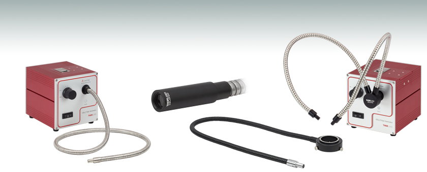
Thorlabs' OSL2 and OSL2IR Fiber-Bundle-Coupled Tungsten-Halogen Light Sources deliver white light for brightfield microscopy, laboratory, and illumination applications. The output illumination intensity is exponentially variable from 0 to 100% using a knob on the front of the unit. The 150 W EKE halogen bulbs have a 3200 K color temperature (see Figure 1.1) and are user replaceable with optional bulbs sold below. These portable fiber-coupled light sources are compatible with 100 to 120 VAC as well as 220 to 240 VAC and includes a location-specific power cord.
Figures G4.1, G4.2, and G4.3 show the light output from the fiber bundle included with the OSL2 lamp. Figure G4.1 shows the highly divergent beam emitted from the fiber bundle when it does not have a lens assembly attached. Figures G4.2 and G4.3 show the beam when the collimation and focusing packages are attached.
LEDFiber OpticIlluminator
The OSL1-SMA fiber bundle adapter allows multimode fiber bundles with SMA connectors to be used as the output of our former OSL1 light source. Our fiber bundles with SMA connectors offer broader operating wavelength ranges than the fiber bundle included with the former OSL1 and the OSL2YFB bifurcated fiber bundle (sold above), and they are available in longer lengths.
The OSL2 high-intensity light source provides effective broad-spectrum illumination for brightfield and reflected light microscopy. It can be used in both epi-illumination and trans-illumination configurations within the Cerna microscopy platform.
These collimation and focusing packages are designed for use with the fiber bundle included with the OSL2 and OSL2IR light sources; the fiber bundle included with the former OSL1 light source; and the replacement fiber bundles sold above. Two 6-32 setscrews that accept a 1/16" hex key secure the tip of the fiber bundle into the back of the collimation or focusing package. Internal SM05 (0.535"-40) threads on the front of each package and a 0.70" (17.8 mm) outer diameter make these directly compatible with our family of Ø1/2" lens tubes and components.
Fiber opticlighting
To install the replacement bulb in the OSL2 or OSL2IR sources, open the door on the top of the unit, as shown in Figure G6.1, and remove the old bulb. Details are available in Chapter 5 of the OSL2 manual or OSL2IR manual.
Thorlabs' High-Intensity Fiber-Coupled Light Sources are designed for illumination of brightfield microscopy setups and general-purpose laboratory use. A removable, 91 cm (36") long, Ø6.4 mm (Ø0.25") effective core fiber bundle is included with each light source. Replacement bundles are available below. Additionally, each light source has an internally SM1-threaded (1.035"-40) output port for custom integration into optomechanical setups.
Fiber OpticLights for Ceiling
The OSL1B replacement bulb is identical to that included with our former OSL1 light source. The bulb has an integrated hot mirror that blocks most of the IR light. Click on the graph icon in Table G7.1 to view the bulb's emission spectrum.
Thorlabs' Fiber Connector Adapters allow fiber patch cables and bundles with standard connectors to be used with the OSL2 and OSL2IR light sources (see Figure G5.1). Vacuum-compatible versions of the SM1FC and SM1SMA are available; the SM1SMAV and SM1FCV adapters are both vacuum compatible down to 10-10 Torr. Please note that the light output from fiber patch cables or bundles will be lower than that of the fiber bundle included with the OSL2 and OSL2IR sources, due to the smaller core or effective core diameter and lower NA. We recommend verifying that any other fiber bundle used with the OSL2 or OSL2IR light sources can sustain the heat from the bulb; please contact Tech Support with inquires.
The cage plates should be separated such that the distance between the fiber tip and the plano side of the lens is 2.23" (56.7 mm), the back focal length of the lens. The cage system provides easy adjustment of the distance between the cage plates while maintaining alignment. Please contact Technical Support if you need further assistance with this installation.
To connect a patch cable, the fiber bundle adapter that comes preinstalled on the OSL2 or OSL2IR sources must first be removed by unscrewing it from the output port. Next, thread the fiber connector adapter into the output port. Each disk has four dimples, two in the front surface and two in the back surface, that allow it to be tightened from either side using either the SPW909 or SPW801 spanner wrench. The dimples do not go all the way through the disk so that the adapters can be used in light-tight applications. For Thorlabs' full line of SM1-threaded adapters, see Terminated Fiber Adapters.
AccessoriesWe offer collimation and focusing packages for the end of the fiber bundle, single-output fiber bundles, a bifurcated fiber Y-bundle with two goosenecked legs, and a microscope ring illuminator. The single-output fiber bundles are available in two varieties: a metal-jacketed replacement bundle for the included bundle and a gooseneck bundle for increased rigidity and easy manual positioning. Longer length fiber bundles are also available as a custom order by contacting Tech Support.
Single-Output Fiber BundleThe OSL2FB Single-Output Fiber Bundle has a flexible stainless-steel housing and is a direct replacement for the bundle included with the OSL2 and OSL2IR Light Sources.
The OSL2 and OSL2IR have built-in universal power supplies and include a location-specific detachable power cord. Additional user-replaceable bulbs can be purchased below. To order the OSL2 or OSL2IR sources without the included fiber bundle, or for general custom order inquiries, please contact Tech Support.


 Ms.Cici
 8618319014500