
Smart Security Lights with Camera - camera & light
Now focus the condenser. The adjustment wheels for the condenser are usually just in front of the focus wheels as you sit at the microscope. Move the condenser slowly up and down whilst looking down the eyepieces. You’ll see that the edge of the circle of light will go in and out of focus (and change from a red fringe to a blue fringe). Make the edges of the circle of light as sharp as you can (Figure 3).

The most outstanding feature of our LED Light Guides is the extreme acceptance angle (NA) for incoming radiation from the light source. Fused silica fiber light guides typically have a NA of 0.3, translating into angles of no more than α ±17.5° for the light they transmit. Every ray coming in with a higher divergence will be rejected and absorbed at the fiber’s light entrance. Ever wondered why silica fiber light guides are promoted as being particularly heat resistant? It is because the rejected radiation creates unwanted heat. In other words, fiber light guides are inefficient. Primelite’s LED Light Guides accept and transmit light with angles of up to ±35° resulting in power delivery that exceeds the capabilities of conventional fiber light guides by a factor of two to three.
Once you have centred the condenser, open up the field diaphragm until the edges of the circle of light just disappear from the field of view (Figure 5).
What is microscopes
It takes less than a minute to set up a microscope for Koehler illumination. This will ensure that the light source evenly illuminates your specimen, produces a sharper image and will increase the contrast between areas of staining or between regions of tissue in your sections. You will also be able to collect more imaging data from each of your specimens.
In the 1893 paper entitled "Ein neues Beleuchtungsverfahren für mikrophotographische Zwecke" which was published in Zeitschrift für wissenschaftliche Mikroskopie und für mikroskopische Technik (“A New System of Illumination for Photomicrographic Purposes” in the Journal of Scientific Microscopy and Microscopic Technique) he set out the main problems microscopists faced at the time. Auer gas lights and zirconia light were the main sources of illumination available in this era, but these had the tendency to produce an unwanted ‘glare’.
Rigid Industries is a leader in LED lights and light bars, including fog lights. We also have mounting for a variety of trucks and other off-road vehicles.
If you require images for use in Powerpoint presentations, poster presentations or for submitting to journals, then Koehler illumination is a must. This simple five step technique goes a long way and, with a little practice, will easily become second nature before you capture your images.
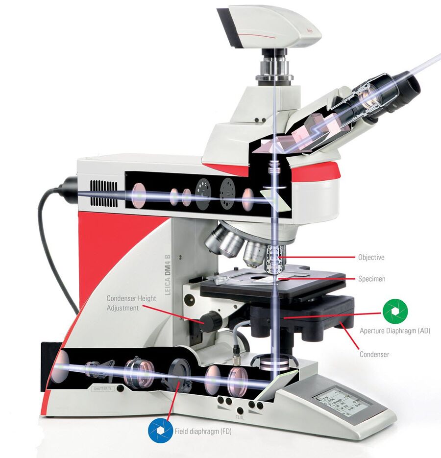
As well as the microscope objectives, there are two other components which you should be aware of (and which are adjusted) for Koehler illumination.
Before you start your imaging session always check to see that the lenses, eyepieces, objectives are clean. The cleaning of microscope lenses is covered in another article, but you should always use lens cleaning tissue and a recommended solvent. Place the slide on the stage, and turn on the lamp to its lowest setting.
Within the sub-stage condenser there are two component parts which are adjusted in setting up correct Koehler illumination. These are the centering screws and the diaphragm. As well as the field diaphragm, the sub-stage condenser also has a light controlling diaphragm which is adjusted by either a slide control or a knurled ring around the condenser similar to the field diaphragm. This diaphragm controls the angle of the light cone which is illuminating the specimen. As I alluded to in my article on Numerical Aperture (NA), the NA of the whole microscope system is not only determined by the objectives. Indeed, when the sub-stage condenser diaphragm is opened, this produces an increase in the NA of the whole instrument resulting in greater resolution, contrast and optimal illumination. The centering screws ensure that the light used to illuminate your slide is directly in the centre of the field of view, thereby offering uniform intensity across the specimen.
Criticalillumination
The Auer gas light was named after the Austrian scientist and inventor, Baron Carl Auer von Welsbach (1858-1929). He is credited for patenting the gas mantle which was used as street lighting throughout Europe. Although Auer gas lights still produced carbonic acid and a certain amount of heat, the London Journal of Gas Lighting and Sanitary Water Supply exclaimed that the Auer light was “eminently suitable” for microscopy.
Expect our LED Light Guides to last for several years if you use them with our fiber-coupled LED light sources. With remarkably efficient light coupling and virtually no excess radiation at the light guide entrance, components do not heat up, preventing premature failure.
Primelite LED Light Guides are designed for continuous throughput of up to 50 watts of optical radiation. Active cores optimized for the near ultraviolet (NUV), visible (VIS), and near infrared (NIR) spectral ranges are available in four cross-sections. Our LED Light Guides’ diameters can range from Ø3.0 to Ø8.0 mm to meet your requirements regarding mechanical configuration setup and transmitted power.
LED light guides are efficient tools, perfect for directing the output of a distant light source to a target point. They are your go-to option for several reasons, perhaps the most compelling being that you need a powerful light source, but have to deal with the constrictions of a tight design envelope. Light-guide-coupled installations also have the edge if you need high radiation output from a freely movable light exit, are aiming for a lightweight design, or have to satisfy strict safety requirements in a controlled environment. In any case, the hallmarks of a good light guide are excellent transmission, high mechanical flexibility, robustness, and reliable performance over a long service life. Primelite’s LED Light Guides tick all these boxes.
The final adjustment is with the iris (or aperture) diaphragm. Just below the centering screws (or above on an inverted microscope) you’ll find another diaphragm similar to the main field diaphragm. Whilst looking down the eyepieces, open this fully, and then start closing it until the image ‘flare’ disappears. By closing the aperture diaphragm, you will increase the contrast of your specimen, but resolution will be decreased. You should find a balance depending on your eyes and the specimen you are viewing.
The Koehler Illumination technique is named after its inventor August Koehler (1866-1948) who published this method in 1893. At the time of publication, most microscopes were reliant on mirrors and gas lamps as sources of illumination. Coupled with the fact that for photomicroscopy, researchers were using emulsion plates which required long exposure times, this often resulted in inconsistency.
Even today, his consistent illumination technique is still widely used and forms the basis of many techniques including confocal, phase contrast and differential interference contrast (DIC) microscopy. Once you know how to set up a microscope for correct Koehler illumination, it should become second nature and will transform your imaging work. It is simply one of the most important principles of light microscopy.
UV adhesives are used extensively for precise positioning/alignment of parts. Compounds can be employed for structural or temporary bonding. Master Bond UV cure ...
All HQL and NAV LED lamps can be operated on conventional control gear (CCG) or directly on 230 V AC and offer a long life and 100% light without warm-up time.
UV Blocking Materials in wide variety of colors for every application. Blue Light Blocking, Amber, Orange, Temporary Screens, Window Films, Rigid sheet, guards.
The technique of Koehler Illumination is one of the most important and fundamental techniques in achieving optimum imaging in any given light microscope set-up. Although it should be routinely used as part of setting up a microscope, many microscopists are put off by thinking that the correct set-up is complex and time consuming and it is therefore still not widely practised. By getting to know the two main components of the microscope which are adjusted in this technique (the diaphragms and sub-stage condenser) in reality, correct set-up should only take a matter of minutes. A correctly aligned microscope can result in greatly improved images of uniform contrast and illumination as well as higher resolution and more detail. In this article, we will look at the history of the technique in addition to how to adjust the components in five easy steps.
Our Advanced LED Light Engines ALE/1 and ALE/3 use high-transmission LED Light Guides to flexibly deliver the optical system output right to the target spot. With perfectly matching numerical apertures, this combination of our LED light sources and light guides makes for a very efficient overall setup. Besides being very flexible and featuring excellent transmission, our standard LED Light Guides are highly customizable. They can be either single- or multi-pole; in some applications, their length extends up to 20 meters.
SCHOTT's Decorative Fiber Optic Lighting solutions offer subtle and cost-effective illumination for museum exhibits, retail showcases, saunas and interior ...
Focusing inmicroscope
From spectacular light shows at big country houses to family-friendly twinkling trails, there's something for everyone.
Once you have the sharp circle of light, look away from the eyepieces and have a look at the condenser component of the microscope. You’ll see the centering screws. You can either centre the condenser with the diaphragm closed down or almost fully open. I usually centre the condenser with the field diaphragm where I left it in step two above - almost fully closed down. Whilst holding the screws, look down the eyepieces once again. As you slowly turn the screws, you’ll see that the circle of light will move across the field of view. You should aim to have the circle in the middle of the view of your specimen (Figure 4).
Fiber-optic collimators are used to launch the light from an optical fiber into a free space collimated beam with specified beam diameter or spot size.
The ‘field diaphragm’ is usually located in the base (in an upright microscope) of the instrument as part of the microscope body (Figure 1). Some older (or simpler) microscopes may just have an ‘on/off’ switch for the light source and there may be no field diaphragm to control the intensity of light from the source. The field diaphragm simply controls the amount of light which finally reaches the slide on the stage. By controlling the amount of light coming from the light source, you are able to reduce glare from the source and this results in images with greater contrast. The field diaphragm is usually controlled by a knurled ring around the lens.
Directly under the stage in an upright microscope (or above the stage but in front of the light source/field diaphragm in an inverted microscope), is the sub-stage condenser (Figure 1). Although it has focus wheels which are similar to the fine/coarse focus of the microscope, this component is used for focusing the light from the light source/field diaphragm and not to bring your specimen into focus.
Köhlerillumination
The alternative zirconia light was an intense chemical light source produced by heating the element zirconium. However, with such light sources, Koehler declared that “it is difficult or impossible to achieve uniform illuminations”. Koehler realised that for consistency in illumination, every single component of the microscope needs to be considered and correctly aligned in relation to each other. By making adjustments to the diaphragms and condensers, he overcame the main problems of overheating and light consistency (even using an opera glass in place of a convex lens!).
Microscope
Source ofilluminationin electronmicroscope
A laser is a device that projects a highly concentrated narrow beam of light which is amplified to great brightness using stimulated radiation.
Focus your specimen, but remember if you are using an instrument in a shared facility, then the microscope settings may be completely misaligned. Firstly, close down the field diaphragm which is either on the base of the instrument in an upright microscope, or above the condenser on an inverted microscope. When you look down the eyepieces, you’ll now just see a small circle of light on your slide (Figure 2).
LIGHT FLUID. $136.00. It regains suppleness, freshness and all its radiance ... There are no reviews yet. Be the first to review LIGHT FLUID Cancel reply.

It is not only the high NA that makes our LED Light Guides perform way better than comparable solutions. Excellent transmission in dedicated spectral ranges is also essential, peaking at 85% for our most popular NUV active core option.
Be sure to check out our LED Performance Optics. Our LED Light Guides’ numerical output aperture is around 0.6 (α ~ ±35°), so our lens systems are remarkably affordable add-ons to reduce divergence or even focus radiation for maximum intensity. Also, LED Performance Optics are an excellent choice if you want to improve the uniformity of the exposure field, which can be hexagonal or square.
... of choice for researchers and agricultural professionals measuring photosynthetically active radiation (PAR) and daily light integral all over the world.
The ‘sub-stage condenser’ collects the majority of the light from the source and focuses it as a cone of image-forming light on the slide placed on the microscope stage. When this condenser is correctly adjusted, the light which illuminates your specimen and enters the objective is fully optimised. This results in a uniform intensity and contrast in the final image. As each of the objectives of a microscope is different, it means that the sub-stage condenser will need to be adjusted when you change magnification.
Not all products or services are approved or offered in every market, and approved labelling and instructions may vary between countries. Please contact your local representative for further information.
LEDs are high-NA light emitters with a broad angular radiation pattern. Efficiency is paramount in setups that pair LEDs with light guides. These light guides have to transmit maximum radiation to the target point. This means the LED source’s NA has to match light guide’s NA. We offer single- and multi-pole liquid light guides perfectly matched to our LED light sources. In our exposure systems, they typically deliver two to three times as much power as conventional silica fiber light guides.


 Ms.Cici
 8618319014500