
New lightweight material is stronger than steel - light material
Author: Mark Fedkin, John A. Dutton e-Education Institute, College of Earth and Mineral Sciences, Penn State University.
White light interferometryvs confocal
The John A. Dutton Institute for Teaching and Learning Excellence is the learning design unit of the College of Earth and Mineral Sciences at The Pennsylvania State University.
White light interferometrymicroscope
The instrument works by scanning in Z and recording the Z position for each and every pixel on the detector for where zero optical path difference (ZOPD) occurred. The objectives are designed so the internal reference and the test path have zero optical path difference at the focal plan of the objective. So, as the scanner moves through Z, when the surface starts to come into focus for each pixel, the inference fringes will become measurable, and the Z position of the center fringe (highest intensity) is recorded as it passes through ZOPD. Our detector is a 1024x1024 camera, which means our scan results in 1,048,576 (x,y,z) coordinates that make up the image.
White light interferometryresolution
The College of Earth and Mineral Sciences is committed to making its websites accessible to all users, and welcomes comments or suggestions on access improvements. Please send comments or suggestions on accessibility to the site editor. The site editor may also be contacted with questions or comments about this course.
CSI refers to a class of optical surface measurement methods wherein the localization of interference fringes during a scan of optical path length provides a means to determine surface characteristics such as topography, transparent film structure, and optical properties. See Wikipedia for more information about Coherence scanning interferometry.
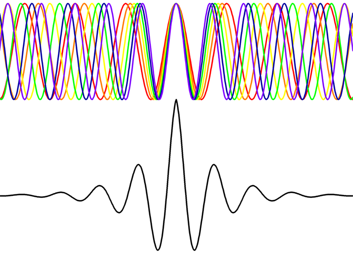
The image to the left depicts a white light source (top) and its distribution of component colors. The coherence length length is inversely proportional to the bandwidth, so the coherence length is very short. The "random" noise of white light produces an inference signal only when the optical path difference between reference and test paths is less than the coherence length of the beam. This can be seen in the resultant wave at the bottom. That center fringe of highest intensity is our point of zero optical path difference and essentially the probe of the interferometer.


 Ms.Cici
 8618319014500