
Light Spectroscopy - 1st Edition - Dr David Harris - light spectroscopy
When white light passes through a prism, it is refracted into all of its colours. If you project this light onto a white surface, you see what looks like a rainbow. All of the colours that make up white light are separated at different angles. This is because each individual colour refracts by a different amount through the prism.
Along a rough surface, the normal points in different ways. This means that all of the light is reflected in different directions.
Along a smooth surface, the normal always points the same way. This means that all of the light is reflected in the same direction.
Sometimes light reflects off a smooth surface, like a mirror or a still lake. When this happens, all of the light is reflected in the same direction. We call this specular reflection.
Shown is a colour diagram of light reflecting off a smooth surface. A long, flat, grey rectangle runs along the bottom edge of the illustration. This is labelled, "Surface." Three blue, parallel arrows point diagonally down to the top of the rectangle. Where the blue arrows touch the surface, three red arrows point diagonally up at the same angle. These look like three V shapes.
Reflection occurs when light traveling through one material bounces off a different material. The reflected light continues to travel in a straight line, but in a different direction.
Solid-state lighting (SSL) technology has advanced rapidly over the past decade. By 2016, SSL saved an estimated $4.7 billion in energy costs through the replacement of legacy light sources with LEDs in buildings and outdoor applications. LED lighting is well on its way to ubiquity across the built environment, proving more energy efficient than any other light source.
Copyright 2024, Let’s Talk Science, All Rights Reserved. Privacy Policy Terms of Use Accessibility Scientific Integrity Policy Complaints Policy
PNNL supports DOE’s mission through research that informs new lighting metrics and methods of measurement adopted by industry standards organizations. These entities include the Institute of Electrical and Electronics Engineers (IEEE), American National Standards Institute, and the Illuminating Engineering Society (IES).
Shown is a colour photograph of a city at night, and its reflection in water. High rise office buildings are close together along the horizon. Their windows twinkle with light. The CN Tower is to the left, lit up in red. All the buildings and their lights are reflected, upside down, in the calm water in the foreground. The water, and the sky above are both dark blue.
Delivered twice each month, we're connecting the most important educational and global topics of our time across all classrooms through STEM-based resources, programs, and activities.
Shown are two colour illustrations of the angles of light reflecting off surfaces. Both illustrations have a long, flat, grey rectangle along the bottom edge. These are labelled "Surface." Vertical, dashed lines stretch down the centre of each illustration, ending at the top centre of each rectangle. These lines are labelled, "Normal." In the left illustration, a blue arrow points diagonally, down and right, to top centre of the surface. This is labelled "Incident Light" in blue letters. A red arrow points diagonally up and right from the top centre of the surface. This is labelled, "Reflected Light" in red letters. A curved line leads from "Normal" out to each of the arrows. The one leading to the "Incident Light" arrow is labelled with a theta symbol and a lower case, italicized i. The one leading to the "Reflected Light" arrow is labelled with a theta symbol and a lowercase, italicized r. The right illustration is the same as the left, except that the angles of the arrows are further away from "Normal". Each of these angles are also labelled with the theta symbol and a lowercase, italicized i, and the theta symbol and a lowercase, italicized r.
At the point where the light enters the second material, the light will travel in a different direction than the incident light. We call this refraction. Refraction happens because the speed of light is different in different materials!
The surface of a lens may also be curved inward on one side or on both sides. When lenses curve inward, we call them concave lenses.
PNNL is helping the nation spark a lighting revolution through increased energy efficiency and improved functionality and quality. The future of lighting—75 percent less energy use in the next two decades—is indeed bright.

The surface of a lens may be curved outward on one side or on both sides. When lenses curve outward, we call them convex lenses.
IShown is a colour illustration of six different blue, curved shapes. In the top row, from the left, the first shape has two sides that are curved outward. In the second shape, the left side is curved outward, while the right side is flat. In the third shape, the left side is curved outward and the right side is curved inward. In the bottom row, from the left, the right and left sides of the first shape are curved inward. In the second shape, the left side is curved inward, while the right side is flat. In the last shape, the left side is curved outward, while the right side is curved inward.
We can make light go in different directions using lenses. A lens is an optical device made of plastic or glass. When light passes through a lens, it can be refracted in predictable directions. The directions depend on the shape of the surfaces of the lens.
Shown is a colour diagram of light bending as it refracts through material. The upper half of the diagram has a light grey background. This is labelled, "Material 1." The lower half has a darker grey background. This is labelled, "Material 2." A dashed, black, runs vertically through the centre of the diagram. This is labelled "Normal". A blue arrow points diagonally from the left side of the top edge of the diagram, through Material 1, to the point where normal crosses from Material 1 to Material 2. This is labelled "Incident Light." It is marked with the theta symbol and the letter i to indicate it depicts the angle of incident light. A green arrow points from here, diagonally through Material 2, to the lower part of the right edge of the diagram. This arrow is labelled "Refracted Light." The space between the arrow and normal is marked with the theta symbol and the letter r to indicate this is the angle of refracted light.
When light passes through a lens that is concave on both sides (biconcave lens), the light is refracted outwards. These beams of light are said to be diverging. With this type of lens, the focal point is in front of the lens.
Shown is a colour diagram of light reflecting off a rough surface. The background of the diagram is dark blue. Along the bottom is a long grey shape, with a flat bottom edge and a jagged, uneven top edge. This is labelled, "Dry road." Three diagonal, parallel white arrows point down to the surface. Where each arrow touches the surface, a yellow arrow points up. These arrows point in three different directions, at different angles.
Not only can light bounce off materials, it can also sometimes travel through materials. When light travels through a uniform material, like air, it goes in straight lines. When light travels through one material and into a second material, interesting things happen!
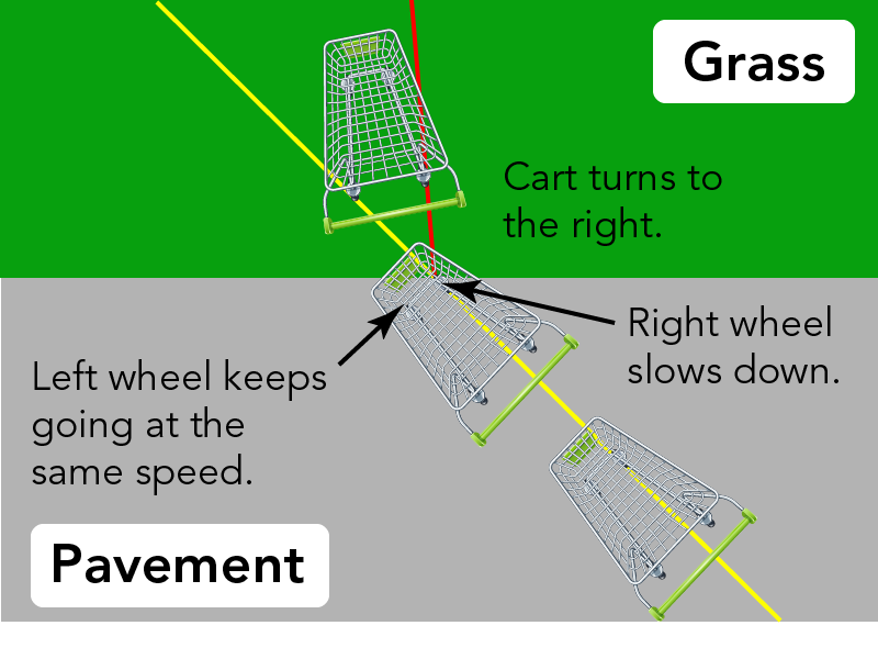
Item contShown is a colour diagram of a shopping cart moving from pavement onto grass. The bottom two thirds of the image is grey. This is labelled "Pavement." The top is green and labelled "Grass." A straight yellow line stretches across the illustration, from near the lower right corner, to near the upper right corner. Two shopping carts are shown from above, along the yellow line. This illustrates that one cart is moving in a straight line, across the grey pavement, toward the grass. The front right corner of the second cart is on the green background, while the rest is on the grey. The front right wheel is labelled "Right wheel slows down." The front left wheel of the cart is labelled "Left wheel keeps going at the same speed." A third cart is completely on the green background. It does not follow the yellow line of the other two.There is a red line under this cart, leading from the edge of the pavement, to a point near the top centre of the illustration. This cart is labelled "Cart turns to the right."ent
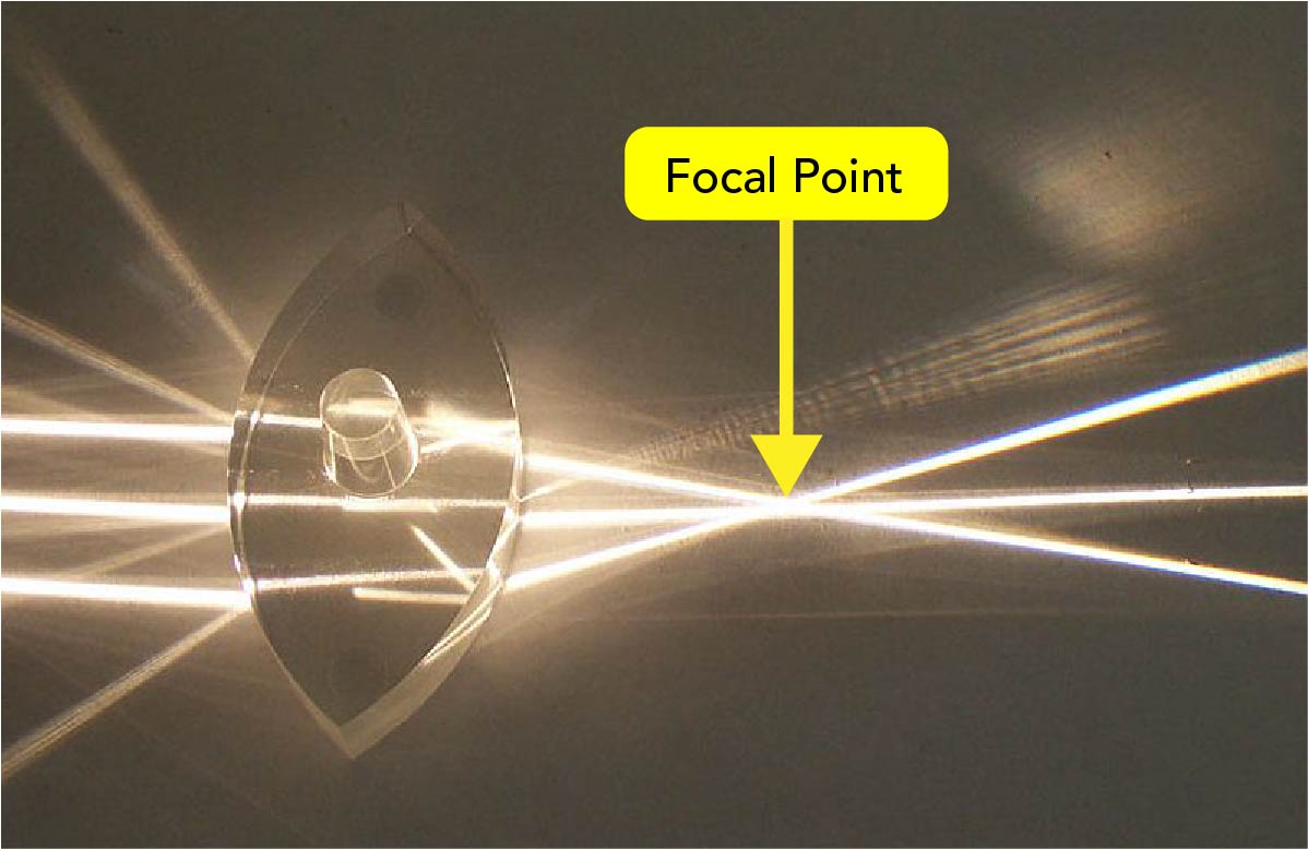
Shown is a colour photograph of three beams of light converging after passing through a lens. The lens looks like the top left shape in the illustration above. It is clear, and has two sides that curve outward. Three thin white beams of light shine from the left edge of the image. When they hit the edge left side of the lens, they turn in toward each other. The beams continue at the same angles through the lens and out the right side. They meet and cross over each other at a point to the right of the lens. This is labelled "Focal Point" with a yellow arrow. The light beams can also be seen reflecting, faintly off the left side of the lens. These diverge from each other.
Sometimes light reflects off a rough surface. When this happens, the light is reflected in different directions. We call this diffuse reflection.
We experience reflection almost every day. When we see ourselves in a mirror, we are seeing a reflection. When we see the sky on the surface of a still lake, we are seeing a reflection.
For example, PNNL led the development of a new way to measure the color rendering capabilities of light sources. This work addressed deficiencies in the existing industry standard, which the lighting research community wrestled with for decades. This new set of metrics in turn enables new lines of research and model-based analysis to relate human visual preference, spectrum, and energy efficiency of light sources.
When light traveling through one material reaches a second material, some of the light is reflected. The rest of the light enters the second material.
The way light changes directions has to do with the properties of the material it is travelling through. Every material has a unique index of refraction. This measurement is identified using the letter n.
It is harder to push the cart in the grass. As each wheel hits the grass, it slows down. Since the wheels on the pavement are still moving faster, the cart changes directions. In this case, the cart turns to the right.
The index of refraction of a material is equal to the speed of light in a vacuum, divided by the speed of light in the material. The higher the index of refraction, the slower light travels in that medium.
Shown is a colour diagram of light reflecting off a rough surface. The background of the diagram is dark blue. Along the bottom is a long grey shape, with a flat bottom edge and a jagged, uneven top edge. This jagged surface is covered with a smooth, blue, stripe, creating a flat top surface. This is labelled, "Wet road." Three diagonal, parallel white arrows point down to the surface. Where each arrow touches the surface, a yellow arrow points up at the same angle. The two sets of arrows resemble three V shapes.
Shown is a colour photograph of three beams of light diverging as they pass through a lens. The lens looks like the bottom left shape in the illustration above. It is clear, and has two sides that curve inward. Three thin white beams of light shine from the left edge of the image. When they hit the edge left side of the lens, they turn in outward, away from each other. The beams continue at the same angles through the lens and out the right side. The light beams can also be seen reflecting, faintly off the left side of the lens. Here, they turn in toward each other. They meet and cross over at a point to the left of the lens. This point is labelled "Focal Point" with a yellow arrow.
When parallel beams of light pass through a lens that is convex on both sides (biconvex lens), the light is refracted inwards. These beams of light are said to be converging. The beams of light cross at a point that we call the focal point. With this type of lens, the focal point is behind the lens.
Shown is a colour illustration of a light beam passing through a prism. The illustration has a large, pale grey, equilateral triangle on a black background. A thin white line extends from the left edge of the image, to the right edge of the triangle. Here the line fans out into a rainbow of colours. Starting from the top, these are: red, orange, yellow, green, blue, indigo and violet. The rainbow grows wider as it moves through the prism and out the other side.
If the road is wet, the water makes the road surface smoother. This results in more specular reflection from the car’s headlights. This causes what we call glare. Glare makes it hard for drivers to see.
If light is travelling in one material and then refracts in a second material, it will bend towards the normal if the index of refraction of the second material, n2, is greater than the index of refraction of the first material, n1.
PNNL is also leading new research on connected lighting systems. By incorporating distributed intelligence, network interfaces, and sensors, these systems become data-collecting platforms that enable a wide range of valuable new capabilities, as well as delivering greater energy efficiency. The Lighting Science and Technology Laboratory in Portland supports this research, with a large high-bay space for testing and evaluating emerging connected lighting systems for energy reporting accuracy, interoperability, system energy performance, and cybersecurity vulnerability.
Shown is a colour diagram of light bending as it refracts through material. The upper half of the diagram has a light grey background. This is labelled, "Material 1." The lower half has a darker grey background. This is labelled, "Material 2." A dashed, black, runs vertically through the centre of the diagram. This is labelled "Normal". A blue arrow points diagonally from the left side of the top edge of the diagram, through Material 1, to the point where normal crosses from Material 1 to Material 2. This is labelled "Incident Light." It is marked with the theta symbol and the letter i to indicate it depicts the angle of incident light. A green arrow points from here, diagonally through Material 2, to the right part of the lower edge of the diagram. This arrow is labelled "Refracted Light." The space between the arrow and normal is marked with the theta symbol and the letter r to indicate this is the angle of refracted light.
Shown is a colour diagram of light reflecting off a rough surface. Along the bottom of the diagram is a long grey shape, with a flat bottom edge and a jagged, uneven top edge. This is labelled, "Surface." Three diagonal, parallel blue arrows point down to the surface. Where each arrow touches the surface, a red arrow points up. These are at three completely different angles.
What is white light? This hands-on activity, by Let’s Talk Science, shows how it is possible to combine colours to make white light.
Shown is a colour photograph of light refracted through a lens marked with angles. At the centre of the image is a circle marked around the edge with degrees in each quarter. In the lower half of this circle is a half-circle of clear, shiny material. A narrow beam of light extends from the end of black cylinder in the top left corner of the photograph. The beam crosses the 60 degree mark of the top left quarter of the circle. This beam is labelled "Incident light." When the light hits the edge of the lens, it goes in two different directions. One faint beam turns diagonally down through the lens at about 35 degrees. This beam is labelled "Refracted light." Another, even fainter beam turns up, diagonally away from the edge of the lens, through the 60 degree mark in the top right quarter of the circle. This beam is labelled "Reflected light."
PNNL has also played an important role in researching and characterizing flicker in LED lighting. This phenomenon was long suspected of causing short- and long-term health effects—including impaired vision, headaches, and even seizures in susceptible populations. PNNL tested early LED products for flicker, providing data that were incorporated into an IEEE standard. This was followed by PNNL testing and accuracy evaluation of several generations of flicker meters. Now widely available, these meters enable SSL technology developers to accurately measure and address flicker in their products and systems.
DOE’s Building Technologies Office, which manages the Solid-State Lighting Program, focuses on research to cut U.S. lighting-related energy use by 75 percent by 2035, while improving lighting quality, functionality, and service.
However, the real excitement stems from the remaining headroom for improving luminous efficacy and advanced control of spectrum, intensity, and light distribution. These advances will deliver intelligent lighting systems many times more efficient and effective than the best current technology. The future of lighting is connected and controllable, with the ability to place the right amount and spectrum of light where and when it is needed. These improvements will optimize vision, productivity, ambiance, security, and also provide physiological benefits.
PNNL maintains a nationally accredited lighting test laboratory and staff expertise to effectively evaluate advanced lighting systems and their applications. Shown here is an Accelerated Long-term Test Apparatus (ALTA) where the light sources are installed and the small sphere moves along the track.


 Ms.Cici
 8618319014500