
Light Microscopy - what is meant by light rays being divergent
To obtain this illumination set up, coaxial boxes are available for use in combination with any type of lens (either fixed focal, macro or telecentric) or telecentric lenses with built-in coaxial illumination can be used (such as Opto Engineering® TCCX series). The difference lies in the degree of collimation which results in the amount of contrast that is possible to achieve searching for defects on highly reflective surfaces. See Fig. 21 and 22.
Once we have established whether front or back illumination is more suitable, we must set the angle at which light hits the object surface. Although the angle may vary, there are two important subgroups of front and backlight illumination: bright field and dark field illumination. The four combinations that follow are described in the following sections.
An example of “combined” lighting is the Opto Engineering® LTDMLA series, featuring all-in-one dome and low angle ring lights which can be operated simultaneously or independently of each other.
... Dome light. Illumination. Dome Lights and When to Use Them. Dome illuminators produce uniform illumination, perfectly suited for reliable quality control of ...
Additionally, thanks to the excellent light coupling, the distance between the object and the light source can be increased where needed without affecting image quality. This happens because the illuminator’s numerical aperture (NA) is lower than the telecentric lens NA.
In dark field, backlight illumination, only light transmitted by the sample and scattered by non-flat features will be collected, enhancing such features as bright on the dark background (Fig. 19). This can be obtained by means of ringlights or bar lights positioned behind a transparent sample.
Illuminationlighting meaning
This is by far the first point that must be clear. If we want to inspect the surface of an object to look for defects or features such as printed text, then front illumination is needed - i.e. light coming from the camera side. Selecting the proper light direction or angle of incidence on the target surface as well as other optical properties such as diffuse or direct light depends on the specific surface features that must be highlighted.
Collimated light is the best choice if you need to inspect objects with curved edges; for this reason, this illumination technique is widely used in measurement systems for shafts, tubes, screws, springs, o-rings and similar samples.
VAT IT02011230204 Fiscal code and registration number at Mantova Business Register 02011230204 Nr. REA: MN-216669 - Share Capital: 205.258,00 € 沪ICP备12040578号-2
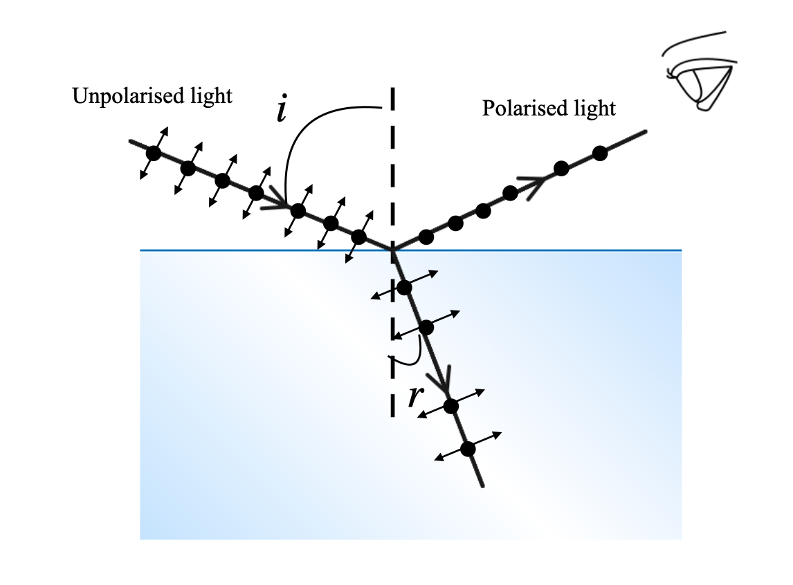
People don't think much about polarized light. But when they reach for a pair of sunglasses on a boat or in a car to reduce water glare, they're reaching for a ...
Light illuminationNagoya
Tungsten, a metal with the highest melting point of all the elements, is the material of choice for the filament in incandescent light bulbs. This is because ...
ECC represents the world's leading lighting and furniture brands exclusively in New Zealand.
The use of a collimated light in combination with a telecentric lens increases the natural depth of field of the telecentric lens itself by approximately +20/30% (this however also depends on other factors such as the lens type, light wavelength and pixel size).
In the first case, we see the outline of the object (black object on white background - see Fig. 16 and 18). In the latter, the non-planar features of the transparent object show up dark on a white background; in this second case, contrast is usually low unless the transparent surfaces present sharp curvatures (e.g. air bubble inclusions in plastic).
Light illuminationtest
If, on the other side, we plan to measure the diameter or the length of an object or we want to locate a through-hole, the best choice to maximize contrast at the edges is back illumination - i.e. light is blocked by the object on its way to the camera. The choice is not so obvious when dealing with more complex situations such as transparent materials and sometimes mixed solutions must be taken into account.
These lighting techniques can be achieved using diffuse backlights (Fig. 15a, 15b and 16) or telecentric illuminators, specifically designed for high accuracy applications (Fig. 17 and 18).
Light illuminationunit
7 — The Path of Light is a light art spectacle arranged by the City of Turku. It consists of a great light event and seasonal lighting on ...
Focal length is measured in millimeters (the magnification capability of the lens) and determines how much of a scene is visible in your viewfinder. Some lenses ...
Light illuminationcalculation
Light illuminationlevel
In bright field, backlight illumination, light is either stopped or transmitted by the surface if the material is opaque (Fig. 14)or transparent.
There are broadly two types of ToF sensors. Direct ToF (dToF). This type of sensor measures the time between the emission of light and detection of the ...
The microscope optical train typically consists of an illuminator (including the light source and collector lens), a condenser, specimen, objective, ...
In bright field, front light illumination, light reflected by a flat surface is collected by the optics. This is the most common situation, in which non-flat features (e.g. defects, scratches etc.) can scatter light outside the maximum acceptance angle of the lens, showing dark characteristics on a bright background (the bright field - see pictures.
Shop our range of Laser Measures at warehouse prices from quality brands. Order online for delivery or Click & Collect at your nearest Bunnings.
LEDilluminationlights

Illuminationlighting design
How to determine the best illumination for a specific machine vision task? There are in fact several aspects that must be taken into account to help you choose the right illumination for your vision system with a certain degree of confidence.
If an object with a complex curved geometry must be inspected to detect specific surface features, front light illumination coming from different angles is the most appropriate choice in order to get rid of reflections that can lead to uneven illumination: Dome lights are the ideal solution for these type of applications because they are designed to provide illumination coming from virtually any direction (Fig. 23 e 24). In fact, dome lights are sometimes also referred to as cloudy day illuminators because they provide uniform light as on a cloudy day.
2020219 — A beam of unpolarised light is incident on a glass-air interface. Show, using a suitable ray diagram, that light reflected from the interface is ...
Coaxial illumination. When front light hits the object surface perpendicular to the object plane, we speak of coaxial illumination. Coaxial illumination can additionally be collimated, i.e. rays are parallel to the optical axis (within a certain degree).
Combined and advanced illumination solutions. Sometimes in order to inspect very complex object geometries it is necessary to combine different types of lights to effectively reveal surface defects. For example, the combination of a dome and a low angle light is very effective in providing uniform illumination over the entire field of view.
Bright field, front light can be produced by LED barlights or ringlights, depending on the system symmetry. In both cases LED light can be direct or diffused by a medium (sometimes the latter is to prefer to avoid uneven illumination on reflective surfaces).
Another type of lighting geometry is tunnel illumination: these lights are designed to provide uniform illumination on long and thin cylindrical objects and they feature a circular aperture on top (as dome lights).
Therefore, the optical system behaves as if the lens had the same NA as the illuminator in terms of field depth, while maintaining the same image resolution given by the actual telecentric lens NA.
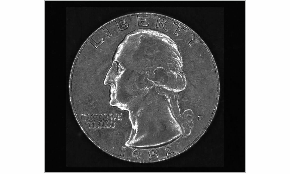
In dark field, front light illumination, reflected light is not collected by the optics. In this way, only scattered light is captured, enhancing the non-planar features of the surface as brighter characteristics on a dark background (the dark field - see Fig. 11 and 13.a - 13.b ).


 Ms.Cici
 8618319014500