
Laser Pointer Safety - ehs.harvard.edu - red laser light
Lighting plays a fundamental role in the effectiveness of any Machine Vision system, and Gardasoft's state of the art Industrial LED Technologies ensure that the highest performance demands can be met for both Area Scan and Line Scan applications. Gardasoft's LED Pulse Controllers are compatible with practically any LED Machine Vision light, providing up to a 10 times increase in light intensity output. Our LED Lighting range has multiple options for wavelengths (including UV and IR), and for Surface and Web Inspection applications it includes high speed Line Lights with an intensity of up to 2500kLux. The Gardasoft White Paper on LED Controller technology is a useful reference for the principles of attaining maximum performance for Machine Vision illumination.
By using pulsing, it is possible to freeze the image of moving objects. Gardasoft's controllers have fine adjustment of the pulse timing, which is often more flexible than the camera timing. The camera can be set for a longer exposure time and the light pulsed on only for a short time to freeze the motion.
One of the key components of machine vision imaging is determining what kind of lighting is optimal for your set-up to achieve the best light-dark contrast; bright field lighting or dark field lighting. Bright field is the more commonly used lighting technique whereas dark field is advantageous when imaging things such as reflective surfaces and edge inspections. In this blog we will discuss the lighting requirements for Bright Field and Dark Field Illumination and their advantages and disadvantages in imaging.
Köhlerillumination
Adimec’s cameras are optimized to have the lowest read noise when they leave the factory. By supporting analog gain the read noise can even further be decreased. This optimization increases the measurement accuracy in the darkest parts of an image. The cameras are calibrated in Adimec’s factory by using a Dark Signal Non-Uniformity (DSNU) calibration. While they are calibrated in factory, these cameras can be re-calibrated in a system to optimize the image even further depending on the use case. This DSNU reduces pixel-to-pixel fixed pattern, which in turn increases the measurement accuracy
Widefield microscope
Converting a constant illumination system to pulsed illumination is straightforward. The trigger for the camera is sent to a lighting controller. The controller provides precise pulse width timing, power and brightness control for the lighting pulse. This ensures that the lighting pulses during the camera exposure time and that the light energy is the same for every image.
Teledyne Adimec is an ISO 9001:2015 certified medium- sized company that designs and produces reliable industrial cameras in small batches to meet customer demands at global OEMs. We serve three strategic markets. – Machine Vision, Healthcare and Global Security.
At their current rating, LEDs and LED Lights will output 100% brightness. However, it is possible to get more than 100% brightness by driving with more current rating for short pulses. This is called Overdriving, and Gardasoft SafePower™ and SafeSense™ technology enables users to do this with ease and complete confidence.
In pulsed mode the lighting is only on when required. The controller receives a trigger signal when a pulse is required. The delay from the trigger to the output pulse, the length of the pulse and the intensity of the pulse are all configurable.
The well known Photo Response Non-Uniformity, or PRNU, calibration is optimized to reduce the pixel-to-pixel variation independent of the shading caused by the camera lens. This calibration combined with bright field lighting allows for the optimization of bright field measurement. Often this calibration is used in conjunction with the Low Frequency Flat Field correction, which is a calibration that not only removes shading caused by the lens, but by using multiple live sets of calibrations it can correct for the shading of the different light sources. Thanks to camera sensitivity matching and these calibrations, the same lighting recipe can be used with each Adimec camera. They all will return the exact same measurement, independent of which camera you put in your machine.
The only answer I can give you why a darkfield image is preferred over a brightfield image: With a darkfield image you clearify the edges or structures of sampels, this method is used to detect or check non-uniformities like a defect or if a required structure is present. Like in the wikipedia site, they do this to see the edges of bloodcells, making them easy to count, check on “roundness”, or detect non-uniformities.
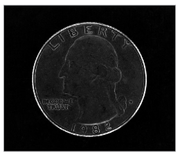
Bright field lighting is the method for imaging reflected light. That is, the light coming from the source is reflected into the camera so that small defects and edges which typically scatter light are not picked up by the camera. This creates a bright image, but areas with engravings, scratches, or indentations may not be as well defined. In addition, due to the reflection of light, reflective surfaces are difficult to image with this lighting set-up. The light source will be scattered less by the object’s surface and more light will be reflected back into the camera, causing a bright spot in the image, as seen below. To properly set up Bright Field Lighting, you want the light sources to be at an angle to the subject or imaging surface of 45 and 90 degrees. Typically positioning these light sources closer to the subject or surface is advantageous, as this helps cover a larger surface area and can help eliminate some of the issues seen with imaging reflective surfaces or edges.
Continuous output is where the lighting is on all the time. This is the easiest mode to use as the intensity of the lighting is the only parameter that needs to be set.
Darkfieldmicroscopy
Ultimately, these lighting techniques are used to help you achieve the key principle of machine vision illumination, which is to capture the correct light-dark contrast in the image. The techniques and principles for dark field and bright field illumination are there to assist you with properly setting up the best illumination for what you are imaging, and it is always advisable to test with a few different illumination set-ups. An inspection may in theory be best suited by bright field illumination, but you may discover that after testing the set-up, there could be a reflection that makes the inspection impossible, at which point understanding the lighting techniques for dark field illumination can assist you in eliminating this reflection.
Criticalillumination
Overdriving is used with Pulsed Lighting, where it brings benefit to most Vision applications. The exceptions being applications where the camera is exposed for a high percentage of the time, for example Line Scan (see Gardasoft VLX Line Scan illumination solutions).
Darkfield microscopy is not a area where we at Adimec specialize in, and we focus mainly on the camera (so only a bit on lighting & lenses), so I can’t give much feedback on your question.
LEDs are current driven devices, and their brightness is approximately proportional to the amount of current flowing through the LED. LEDs have a current rating (which is closely controlled), and a voltage rating (which can vary widely from batch to batch). Therefore for high performance, high precision vision applications it is essential to accurately control the current within any associated LED lighting device.
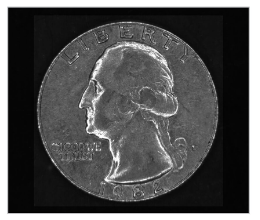
Unlike in bright field lighting, where reflected light is imaged, dark field lighting only captures scattered light. By imaging only the scattered light, edges and surface defects become more prominent in the image as they are the things that best scatter light. To best set up a light source for this light scattering, a low angle of light (usually from ring lights) of around 10-15 degrees is ideal. This low angle allows for edges, defects, ridges, etc. to properly scatter the light while not having the surface of the target reflect too much light back to the camera. This technique can also be used to effectively inspect highly reflective or mirrored surfaces which you would otherwise be unable to inspect with bright field lighting.
Whoever I looked into darkfield Microscopy, and there is a short animation of how it works on wikipedia (https://en.wikipedia.org/wiki/Dark-field_microscopy) To work with this method to check on exomes, I can imagine some wavelengths work better than others based on the type and size of the exome (so that specific light is scattered more and gives a better/sharper image results) I do not have any formulas to for you to work with, but note that a lot of factors are dependent on the setup you are using (lenses, wavelength, size and angle of darkfield patch stop, and distances from Lightsource-to sample- to camera, in addition to the sample properties (thickness, transparency etc).
Hi Scott, let me introduce myself, Recently I’m doing research to build a Dark Field Microscopy that is able to observe an exosome. So, if you willing you can reply my question by emailing me. I want to ask about the light that we can use for darkfield microscope. Which do you recommend between using laser or light to apply it to the darkfield microscope and can you provide the potential candidate of the light source? . Second question is how we know the required intensity is needed for the dark field imaging system (if know do you know how to calculate it?). Third question do you know the reason why darkfield will achieve better resolution than brightfield? (if you know the calculation you can provide to me).
See below a comparison of images taken with Bright Field Illumination and images taken with Dark Field illumination to see the differences between the two lighting techniques:


 Ms.Cici
 8618319014500