
Interior Light - domelight
An interactive GUI is available in this tab to demo all the features of the PM60 and PM61 Series Power Meters. A full-screen demo is also available by clicking the button to the right. For computers with a touchscreen, the demo supports all swipe gestures to switch screens. Otherwise, a mouse or directional and enter keys can be used to interact with these functions. The GUI provides the opportunity to browse all submenus and change settings. For information on navigating the measurement and menu screens, please see the PM60 and PM61 Series Power Meter manual.
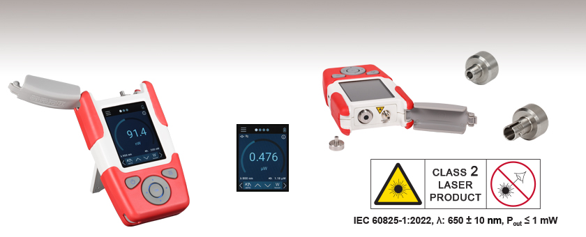
The PM61 series power meters are equipped with a Visual Fault Locator (VFL) consisting of a 650 nm class 2 guide laser and 2.5 mm ferrule receptacle which can be used to find fibers in a bundle, breaks in a fiber, or alignment into an optical fiber. The VFL can be used in a continuous wave (CW), 1 Hz flashing, or 3 Hz flashing setting.
Labsphere
It is not safe to use the detector to measure this pulsed laser emission, since the peak power of the pulses is >5 orders of magnitude higher than the detector's maximum peak optical input power.
The PM60 Series Fiber Optic Power Meters are robust, handheld instruments that are ideal for both lab and field applications. Each unit includes a rechargeable 2300 mAh LiPo battery that has the capacity for continuous operation throughout a workday.
The PM61 Series Fiber Optic Power Meters are robust, handheld instruments that are ideal for both lab and field applications. Each unit includes a rechargeable 2300 mAh LiPo battery that has the capacity for continuous operation throughout a workday. The PM61A power meter features an internal Si sensor for measuring wavelengths from 400 nm to 1100 nm at optical powers from -65 dBm to +16 dBm (300 pW - 40 mW). The PM61C and PM61CH power meters both feature an InGaAs sensor for measuring wavelengths from 800 - 1700 nm and are sensitive to optical powers from -70 dBm to +13 dBm (100 pW - 20 mW) and -55 dBm to +23 dBm (3 nW - 200 mW), respectively.
Multiple data measurement and analysis functions are integrated into the GUI package. The interface offers a user-friendly design with minimal use of color and low brightness that is ideal use in dark lab environments while wearing laser safety glasses. Measured data can be displayed in real time as a simulated analog needle, digital values, line graph, or bar graph. Continuously logged and short-term measurements can be recorded for data viewing and analysis at a later point. A built-in statistics mode analyzes measured data and continuously updates to reflect new measurements within the pre-determined measurement period. Beam position measurements are also supported when used with our thermal position & power sensors.
International Light
The demo offers access to all the features of the PM60 or PM61 Series Power Meters that are selectable while using either the touchscreen or the physical keypad with limited configurability. The simulated measured power level can be set over several decades and simulated measurements can be performed displaying as it would on the physical device.
Pulsed laser radiation parameters are illustrated in Figure 1 and described in the table. For quick reference, a list of equations is provided below. The document available for download provides this information, as well as an introduction to pulsed laser emission, an overview of relationships among the different parameters, and guidance for applying the calculations.
UVA LED
Is it safe to use a detector with a specified maximum peak optical input power of 75 mW to measure the following pulsed laser emission?
Remote OperationThe PM60 and PM61 series power meters can be controlled remotely using Thorlabs' Optical Power Monitor (OPM) software. Both series feature a USB 2.0 interface to connect to a PC. Additionally, the PM61 series has a built in Bluetooth module that allows the user to establish a wireless connection to a PC. Remote connectivity allows the user to access the power meter settings, visualize power measurements, and record data directly through the OPM software. Please see the Software tab for details.
ILT2400
Device DesignThe PM60 and PM61 series power meters can be operated using both a 2.8" capacitive touchscreen and the physical keys shown in the image above. An interactive GUI is available to demo all the features (click here or see the Interactive Demo tab). Each power meter comes with a USB C rechargeable, lithium polymer (LiPo) battery with a 2300 mAh capacity. The PM61 series power meters feature an additional wireless charging capability via an inductive charging coil. Each power meter is shipped with an SM05 (0.535"-40) internally threaded PM20-25 adapter for fiber patch cables with 2.5 mm ferrules. The PM20-25 adapter is designed without a locking mechanism to allow for fast and efficient power measurements using patch cables with a variety of terminations.
The Optical Power Monitor software GUI enables seamless control of up to eight power meters that are connected via USB, RS232, or Bluetooth® wireless technologya. The latest software, firmware, drivers, and utilities for these power meters can be downloaded here.
Each unit is shipped with a PM60 or PM61 series power meter with an attached PM20-25 fiber adapter, USB cable (Type A to Type C), Certificate of Calibration, and Quick Reference.
Additionally, the PM61 series features user configurable menus along with Admin / User levels to ensure operation is customizable and secure for all users.
The PM60 and PM61 Series of Fiber Optic Power Meters are robust, full-featured, handheld instruments, which together cover the full range of optical fiber applications within the 400 - 1700 nm range with optical powers ranging from -70 dBm to +23 dBm (100 pW - 200 mW). A rugged enclosure, internal sensors, kickstand, and hand strap eyelet (hand strap not included) make these models ideal for field or lab applications. The PM60A and PM61A power meters use a Si sensor for detection between 400 nm and 1100 nm, while the PM60C, PM60CH, PM61C, and PM61CH use an InGaAs sensor for detection between 800 nm to 1700 nm.
Each PM61 series fiber optic power meter contains an integrated VFL that emits ≤1 mW at 650 nm and can be used for detecting fibers in a bundle, breaks in an optical fiber, or aid in free-space to fiber alignment. The VFL can be operated in CW, Flashing: 1 Hz, or 3 Hz modes via the touchscreen or physical buttons on the device, or using the OPM software GUI.
Determining whether emission from a pulsed laser is compatible with a device or application can require referencing parameters that are not supplied by the laser's manufacturer. When this is the case, the necessary parameters can typically be calculated from the available information. Calculating peak pulse power, average power, pulse energy, and related parameters can be necessary to achieve desired outcomes including:
Analysis ToolsThe Fiber Power Meter Series offer Data Logging and Statistics analysis tools which allow for power levels over a specified time period to be recorded and saved on the internal memory to be accessed at a later time using the USB connection and an external PC. The Data Logging tool shows a time trace of the power levels over the given interval while the Statistics tool shows the number of samples, elapsed time and mean, maximum, and minimum power levels. The PM61 series also features the Pass / Fail Analysis tool which gives a visual indication to whether a given measurement is within a predefined power range.
Figure 1: Parameters used to describe pulsed laser emission are indicated in the plot (above) and described in the table (below). Pulse energy (E) is the shaded area under the pulse curve. Pulse energy is, equivalently, the area of the diagonally hashed region.
The Optical Power Monitor software package installs the GUI, which then can be used to control the touchscreen, handheld, or USB-interface power meters. Firmware updates for supported power meters are also available. Programming examples and drivers for interfacing with our power and energy meter consoles using LabVIEW, C/C++, Visual C#, and Python are installed with the software; refer to the manual for details.
These adapters are compatible with devices that feature external SM05 threading such as our S15xC Series Fiber Power Meter Sensors, PM160 wireless power meter, and the Fiber Optic Power Meters above. One PM20-25 wide-key FC/PC fiber adapter is included with each of the power meters sold above. For details on narrow versus wide key connectors, please see our Intro to Fiber tutorial.
The PM20-25 ferrule adapter is designed without a locking connector mechanism and accepts fiber patch cables with Ø2.5 mm ferrules for quick power meter measurements.
The PM60A power meter features an internal Si sensor for measuring wavelengths from 400 nm to 1100 nm at optical powers from -65 dBm to +16 dBm (300 pW - 40 mW). The PM60C and PM60CH power meters both feature an InGaAs sensor for measuring wavelengths from 800 - 1700 nm and are sensitive to optical powers from -70 dBm to +13 dBm (100 pW - 20 mW) and -55 dBm to +23 dBm (3 nW - 200 mW), respectively.
The Optical Power Monitor GUI software features power measurement, readout from up to eight power meters, and remote wireless operation.
Please note that the Optical Power Monitor Software uses different drivers than the Power Meter Utilities Software and Thorlabs recommends using the new driver TLPM.dll. For users who wish to use the legacy Power Meter Software or use custom software designed using the older PM100D.dll driver, a Power Meter Driver Switcher program is included for easy swapping of the installed driver between the two versions.
The PM101 Series Power Meters are only compatible with version 2.0 or later. The PM102 Series Power Meters are only compatible with version 2.1 or later. The PM103 Series Power and Energy Meters are only compatible with version 3.0 or later. The PM5020 Console is only compatible with version 4.0 or later. The PM60 and PM61 Power Meter Series are only compatible with version 6.0 or later.


 Ms.Cici
 8618319014500