
Fiber Optic for LED Lights - fiber optic light cable
The diagram to the right shows the male connector of the LEDRW40 Ring Light. It is a standard M8 x 1 sensor circular connector. Pins 1 and 2 are the connection to the LED. Pin 3 and 4 are used for the internal EEPROM. If using an LED driver that was not purchased from Thorlabs, be careful that the appropriate connections are made to Pin 1 and Pin 2 and that you do not attempt to drive the LED through the EEPROM pins.
Driver OptionsThorlabs offers four drivers compatible with this LED ring light: LEDD1B, DC40, UPLED, and DC2200. See the LED Drivers tab for compatibility information and a list of specifications. The UPLED, DC40, and DC2200 drivers are capable of reading the current limit from the EEPROM chip of the connected LED ring light and automatically adjusting the maximum current setting to protect the LEDs. The DC40 LED driver can provide drive currents with up to a 5 kHz modulation when supplied with an external modulation signal. While the DC2200 driver is capable of modulating frequencies up to 250 kHz, the LED ring light must not be modulated at or above 9 kHz.
For convenient connection to the drivers listed below and on the LED Drivers tab, the LED ring light has a connection cable with an M8 connector; see the Pin Diagram tab for the M8 connector pin information. This LED ring light also features an EEPROM chip which stores information about the LED (e.g., current limit, forward voltage). When controlled by a Thorlabs UPLED, DC40, or DC2200 LED driver, this data can be used to implement smart safety features.
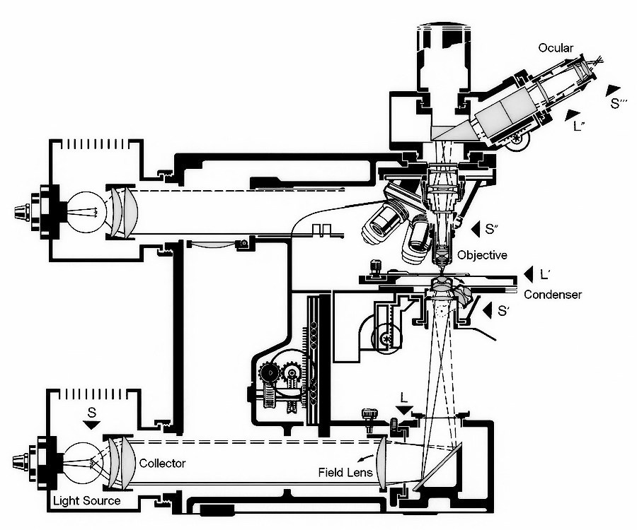
August Köhler described this type of illumination in 1893 [1]. A converging lens (usually referred to as Köhler lens) is placed close to the field stop to form an image of the source in the front focal plane of the condenser. In most microscopes, the so called Köhler lens is replaced by a collector inside the lamp housing and a field lens close to the field stop (see Fig. 1). The rays from each source point then emerge from the condenser as a parallel beam of light. This arrangement has the advantage that any irregularities in the brightness distribution of the source do not cause unevenness in the field illumination.
Please report any Web problems or offer general comments to the Micscape Editor, via the contact on current Micscape Index. Micscape is the on-line monthly magazine of the Microscopy UK web site at http://www.microscopy-uk.org.uk.
Thorlabs also offers a range of unmounted, mounted, collimated, and fiber-coupled LEDs that are designed for a variety of applications, including microscopy, illumination, and measurements. For questions on choosing an appropriate LED and to discuss mounting requirements, please contact Tech Support.
Resolution of two closely spaced diffraction spots in the image plane obtainable with any setup using transmitted illumination is given by the resolution of the objective and the resolution of the condenser. When the numerical aperture of the objective (NAObjective) is larger than the one of the condenser (NACondenser), the smallest, resolvable separation d (Rayleigh criterion) for a given wavelength λ is calculated using the following empirical rule d[μm] = 1.22 λ[μm] / (NACondenser + NAObjective)
Regarding the resolution obtained with various implementations of Köhler illumination, I could not deduce any change in observed resolution when switching between true Köhler illumination and any of the modified versions mentioned above. (My experiments were conducted with diatom preparations in oblique light.)
Conjugate object planes: field (or lamp) diaphragm, object (or specimen) plane, real intermediate image plane (located at the eyepiece field stop), retina or camera sensor.
Fig. 3: Top view of 6V/30W Lamp Housing for Leitz Ortholux. Frosted collector lens is shown Fig. 4: Slightly frosted collector lens for the Leitz Lamp Housing 100 Fig. 5: Clear collector lens for the Leitz Lamp Housing 100 Fig. 6: Frosted glass for Leitz Lamp Housing 50 for Ortholux II
科勒照明
[2] Charles P. Shillaber, Photomicrography in Theory and Practice, Illumination by Method III, p. 96, 3rd edition, John Wiley & Sons, Inc., New York (1947). [3] J.G. Delly, Photography through the Microscope, 9th edition, 2nd printing, Eastman Kodak Company, Rochester (1988).
White Light LEDsThis illuminator is a daylight white LED ring featuring a broad spectrum that spans several hundred nanometers; see the table to the right for a typical output spectrum. It has a correlated color temperature 5500 K, which indicates that the color appearance is similar to a black body radiator at the same temperature. In general, warm white LEDs offer a spectrum similar to a tungsten source, while cold white LEDs have a stronger blue component to the spectrum; daylight white LEDs provide a more even illumination spectrum over the visible range than warm white or cold white LEDs. To discuss LED ring lights with other correlated color temperatures or nominal wavelengths, please contact Tech Support.
Criticalillumination
This microscope illumination is also known as Nelsonian or "source-focused" illumination. It was first developed by British microscopist Edward Milles Nelson (1851 – 1938). A uniformly bright light source, which could be given by an illuminated frosted glass, is placed close behind the field stop. The condenser images points of this light source on to the object plane of the microscope objective (location of specimen). Historically, the flame of an oil or gas lamp was projected via a silver coated mirror into the condenser. Of course, in this case, the bright light source is not close behind the field stop but a few inches apart. These natural light sources provide an essentially structure-less source of illumination. With the introduction of electric lighting using lamp filaments, critical illumination without the additionally added frosted glass was rendered less suitable.
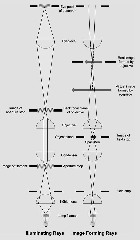
Fig. 1: Aperture planes (denoted with "S") and object planes (denoted with "L") inside the Leitz Orthoplan microscope In summary, Köhler illumination has the following main advantages. First, it provides an even illumination in the specimen plane and all its conjugate planes. Second, this type of illumination positions two different sets of conjugate focal planes (conjugate object planes and conjugate aperture planes) at specific locations along the optic axis of the microscope. Conjugate object planes: field (or lamp) diaphragm, object (or specimen) plane, real intermediate image plane (located at the eyepiece field stop), retina or camera sensor. Conjugate aperture planes: lamp filament, front aperture of condenser (location of condenser diaphragm), back focal plane of objective, exit pupil of eyepiece (location of the pupil of the observer's eye). A diagram showing the conjugate aperture and object planes for the Köhler illumination is provided in Fig. 2. Fig. 2: Köhler illumination showing all conjugate object and conjugate aperture planes It is important to note that many microscopes do not support true Köhler illumination but a modified version of this type of illumination. In this modification, a diffusing plate is placed in front of the source and the lamp lens focuses the surface of the diffusing plate in the first focal plane of the condenser [2]. In other designs, such as the 6V/30W illuminator of the Leitz Ortholux (see Fig. 3) or in some 12V/100W illuminators of the Leitz Orthoplan (see Fig. 4), the collector lens located inside the lamp housing is slightly frosted in order to distribute light more uniformly. Last but not least, we commonly find a frosted glass (a.k.a. ground glass) just following the collector lens (when seen from the source), as implemented for the 12V/50W lamp housing for the Leitz Ortholux II (see Fig. 6). To establish Köhler illumination, this frosted glass will be removed before focusing an image of the filament into the back focal plane of the objective (see Fig. 2 for the location of the back focal plane of the objective). After completing the process of establishing Köhler illumination, the frosted glass is reinserted. In case of a frosted collector lens, the diffuse image of the filament must be projected into the back focal plane of the objective. - The proper procedure to establish Köhler illumination is illustrated in many textbooks about microscopy or photomicrography. One of the best illustrated descriptions on how to properly setup Köhler illumination has been published by J.G. Delly [3]. Fig. 3: Top view of 6V/30W Lamp Housing for Leitz Ortholux. Frosted collector lens is shown Fig. 4: Slightly frosted collector lens for the Leitz Lamp Housing 100 Fig. 5: Clear collector lens for the Leitz Lamp Housing 100 Fig. 6: Frosted glass for Leitz Lamp Housing 50 for Ortholux II
Many implementations of critical illumination exist. Most lower cost microscopes use some sort of critical illumination. However, if no condenser is used, no image of the light source can be projected into the specimen plane. An illumination that does not form an image of the source somewhere inside the optical path of the microscope is known as afocal or nonfocused illumination.
Fig. 3: Top view of 6V/30W Lamp Housing for Leitz Ortholux. Frosted collector lens is shown Fig. 4: Slightly frosted collector lens for the Leitz Lamp Housing 100 Fig. 5: Clear collector lens for the Leitz Lamp Housing 100 Fig. 6: Frosted glass for Leitz Lamp Housing 50 for Ortholux II
Conjugate aperture planes: lamp filament, front aperture of condenser (location of condenser diaphragm), back focal plane of objective, exit pupil of eyepiece (location of the pupil of the observer's eye).
At low to medium magnifications, I observed that any type of modified Köhler illumination will slightly improve the evenness of the illumination. - With the introduction of LED’s, new challenges had to be solved. Nikon introduced a special fly-eye lens in front of a single, high performance LED to compensate for any unevenness in illumination caused by the very different geometry of an LED. Whether such a fly-eye lens is required or a simple frosted glass would suffice is debatable.
This tab includes all LEDs sold by Thorlabs. Click on More [+] to view all available wavelengths for each type of LED pictured below.
Thorlabs' LED Ring Light Source consists of 40 individual broadband, daylight white LEDs in a ring-shaped array with a Ø0.99" (Ø25.1 mm) clear aperture. By angling the LEDs, this ring light illuminates areas from 50 mm to 300 mm along the emission axis that can then be viewed through the clear aperture, making it ideal for machine vision applications.
Microscopy UK Front Page Micscape Magazine Article Library © Gregor Overney First published in the December 2017 edition of Micscape Magazine. Please report any Web problems or offer general comments to the Micscape Editor, via the contact on current Micscape Index. Micscape is the on-line monthly magazine of the Microscopy UK web site at http://www.microscopy-uk.org.uk.
Constructed from anodized aluminum, this LED ring light housing features four 4-40 tapped holes that are compatible with our Ø6 mm ER cage rods, allowing for integration with 30 mm cage systems. The housing also features three setscrews on the sides for interfacing with various camera lenses and high-magnification zoom lens systems (as seen in the photo in the bottom right), which can be secured using a 5/64" (2.0 mm) hex key or balldriver. An M60 x 1.0 external thread at the head of the ring light gives the option of attaching various elements such as custom filters or diffusers.
In summary, Köhler illumination has the following main advantages. First, it provides an even illumination in the specimen plane and all its conjugate planes. Second, this type of illumination positions two different sets of conjugate focal planes (conjugate object planes and conjugate aperture planes) at specific locations along the optic axis of the microscope.
To fully support the max optical power of the LED you intend to drive, ensure that the max voltage and max current of the driver are equal to or greater than those of the LED.
In the following discussion, I assume a nonluminous object under a microscope being illuminated from behind (transmitted illumination). I discuss a few important issues related to Köhler illumination and critical illumination.
With Köhler illumination, the illumination source is perfectly focused into the front focal plane of the condenser and each of its conjugate aperture planes. This requires that the illumination source is sufficiently planar, which is not the case for any type of arc lamp and incandescent light sources. Consequently, only light from a central plane of the illumination is correctly focused into the front focal plan of the condenser (location of the aperture stop). Light emerging from outside the central plane will not be “perfectly” focused at any conjugate aperture plane. This deficiency of true Köhler illumination leads to some level of uneven illumination inside the specimen plane. Highly corrected condensers, such as the aplanatic-achromatic condensers, do not further contribute to the effect of uneven illumination. However, the differences in evenness of illumination caused by various degrees of optical corrections of the condenser system are very subtle and not easily measured due to the more serious issue with the non-planar shape of the illumination source. Using an illuminated ground glass can provide a more planar illumination source and consequently lead to more even illumination than any implementation of true Köhler is able to provide.
Fig. 2: Köhler illumination showing all conjugate object and conjugate aperture planes It is important to note that many microscopes do not support true Köhler illumination but a modified version of this type of illumination. In this modification, a diffusing plate is placed in front of the source and the lamp lens focuses the surface of the diffusing plate in the first focal plane of the condenser [2]. In other designs, such as the 6V/30W illuminator of the Leitz Ortholux (see Fig. 3) or in some 12V/100W illuminators of the Leitz Orthoplan (see Fig. 4), the collector lens located inside the lamp housing is slightly frosted in order to distribute light more uniformly. Last but not least, we commonly find a frosted glass (a.k.a. ground glass) just following the collector lens (when seen from the source), as implemented for the 12V/50W lamp housing for the Leitz Ortholux II (see Fig. 6). To establish Köhler illumination, this frosted glass will be removed before focusing an image of the filament into the back focal plane of the objective (see Fig. 2 for the location of the back focal plane of the objective). After completing the process of establishing Köhler illumination, the frosted glass is reinserted. In case of a frosted collector lens, the diffuse image of the filament must be projected into the back focal plane of the objective. - The proper procedure to establish Köhler illumination is illustrated in many textbooks about microscopy or photomicrography. One of the best illustrated descriptions on how to properly setup Köhler illumination has been published by J.G. Delly [3]. Fig. 3: Top view of 6V/30W Lamp Housing for Leitz Ortholux. Frosted collector lens is shown Fig. 4: Slightly frosted collector lens for the Leitz Lamp Housing 100 Fig. 5: Clear collector lens for the Leitz Lamp Housing 100 Fig. 6: Frosted glass for Leitz Lamp Housing 50 for Ortholux II
.jpg)
It is important to note that many microscopes do not support true Köhler illumination but a modified version of this type of illumination. In this modification, a diffusing plate is placed in front of the source and the lamp lens focuses the surface of the diffusing plate in the first focal plane of the condenser [2]. In other designs, such as the 6V/30W illuminator of the Leitz Ortholux (see Fig. 3) or in some 12V/100W illuminators of the Leitz Orthoplan (see Fig. 4), the collector lens located inside the lamp housing is slightly frosted in order to distribute light more uniformly. Last but not least, we commonly find a frosted glass (a.k.a. ground glass) just following the collector lens (when seen from the source), as implemented for the 12V/50W lamp housing for the Leitz Ortholux II (see Fig. 6). To establish Köhler illumination, this frosted glass will be removed before focusing an image of the filament into the back focal plane of the objective (see Fig. 2 for the location of the back focal plane of the objective). After completing the process of establishing Köhler illumination, the frosted glass is reinserted. In case of a frosted collector lens, the diffuse image of the filament must be projected into the back focal plane of the objective. - The proper procedure to establish Köhler illumination is illustrated in many textbooks about microscopy or photomicrography. One of the best illustrated descriptions on how to properly setup Köhler illumination has been published by J.G. Delly [3].


 Ms.Cici
 8618319014500