
Leica Camera Wetzlar Germany – Official | International - inter camera
The properties of IR light can be useful in vision inspection for a variety of reasons. First, IR light is effective at neutralizing contrast differences based on color, primarily because reflection of IR light is based more on sample composition rather than color differences. You can use this property when less contrast, normally based on color reflectance from white light, is the effect you want (see Figure 12).
Glass and plastic become optically active when stressed; the greater the stress, the greater the effect. Optical stress analysis on complicated shapes can be performed by making plastic models of them and observing them through crossed filters, as seen in Figure 14. It is apparent that the effect depends on wavelength as well as stress. The wavelength dependence is sometimes also used for artistic purposes.
Sample composition can greatly affect what happens to task lighting impinging on a part. Some plastics may transmit light only of certain wavelength ranges and are otherwise opaque; some may not transmit, but rather internally diffuse the light; and still some may absorb the light only to re-emit it at the same wavelength or at a different wavelength (fluorescence). Fluorescence labels and dyes are commonly used in inks for the printing industry as well (Figure 11).
Figure 12. (a) Polarized light is rotated 90º by a liquid crystal and then passed by a polarizing filter that has its axis perpendicular to the original polarization direction. (b) When a voltage is applied to the liquid crystal, the polarized light is not rotated and is blocked by the filter, making the region dark in comparison with its surroundings. (c) LCDs can be made color specific, small, and fast enough to use in laptop computers and TVs. (credit: Jon Sullivan)
Figure 9. Long molecules are aligned perpendicular to the axis of a polarizing filter. The component of the electric field in an EM wave perpendicular to these molecules passes through the filter, while the component parallel to the molecules is absorbed.
Additionally, Figures 3 and 4 illustrate several other relevant points to consider when selecting a camera and light source:
Particularly when used to block specular reflections on samples, any use of polarization filters comes with inherent compromises. The images depicted in Figure 15 demonstrate moderately effective and highly effective use of polarization filters specifically for blocking glare. In samples depicted in Figure 15a–c, you see that glare reflected from a curved surface, such as this personal care product bottle, can be controlled but not entirely eliminated (see Figure 15b center area). This is true because multiple reflection directions are produced on the curved surface from a directional light source, and polarization filters cannot block all vibration directions simultaneously, thus always leaving some areas vignetted. In this case, a more effective approach to glare control, given the flexibility to do so, is to reconsider the lighting geometry. By simple moving the light from a coaxial position around the lens to a relatively high angle, but off-axis position, you can completely eliminate all specular reflection. Conversely, for the relatively flat and planar jar top surface depicted in Figure 15d–e, you can largely remove the specular glare, producing a clear image for inspection. However, a caveat for using dual polarizers is that they can reduce the allowable light considerably—up to 2 ½ f-stops in the case of the jar top example, which could be detrimental for high-speed, light-starved inspections.
Consider not only a source’s brightness but also its spectral content (Figure 3). Microscopy applications, for example, often use a full-spectrum quartz halogen, xenon, or mercury source, particularly when imaging in color; however, a monochrome LED source is also useful for a black and white CCD camera, and also now for color applications, with the advent of “all color—RGB” and white LED light heads.
Figure 14. Optical stress analysis of a plastic lens placed between crossed polarizers. (credit: Infopro, Wikimedia Commons)
What angle is needed between the direction of polarized light and the axis of a polarizing filter to reduce its intensity by 90.0%?
By now you can probably guess that Polaroid sunglasses cut the glare in reflected light because that light is polarized. You can check this for yourself by holding Polaroid sunglasses in front of you and rotating them while looking at light reflected from water or glass. As you rotate the sunglasses, you will notice the light gets bright and dim, but not completely black. This implies the reflected light is partially polarized and cannot be completely blocked by a polarizing filter.
ArmadilloLIGHTING
Figure 8. Polarization by reflection. Unpolarized light has equal amounts of vertical and horizontal polarization. After interaction with a surface, the vertical components are preferentially absorbed or refracted, leaving the reflected light more horizontally polarized. This is akin to arrows striking on their sides bouncing off, whereas arrows striking on their tips go into the surface.
Brewster’s law: [latex]\tan\theta_{\text{b}}=\frac{{n}_{2}}{{n}_{1}}\\[/latex], where n1 is the medium in which the incident and reflected light travel and n2 is the index of refraction of the medium that forms the interface that reflects the light
The objective of this detailed analysis and application of what might be termed a “tool box” of lighting types, techniques, tips, and tricks is to help you arrive at an optimal lighting solution that takes into account and balances issues of ergonomics, cost, efficiency, and consistent application. This helps you to better direct your time, effort, and resources—items better used in other critical aspects of vision system design, testing, and implementation.
Figure 4. The slender arrow represents a ray of unpolarized light. The bold arrows represent the direction of polarization of the individual waves composing the ray. Since the light is unpolarized, the arrows point in all directions.
While you are undoubtedly aware of liquid crystal displays (LCDs) found in watches, calculators, computer screens, cellphones, flat screen televisions, and other myriad places, you may not be aware that they are based on polarization. Liquid crystals are so named because their molecules can be aligned even though they are in a liquid. Liquid crystals have the property that they can rotate the polarization of light passing through them by 90º. Furthermore, this property can be turned off by the application of a voltage, as illustrated in Figure 12. It is possible to manipulate this characteristic quickly and in small well-defined regions to create the contrast patterns we see in so many LCD devices.
As might be expected, the Geometry Independent Area implies that relatively flat and diffuse surfaces do not require specific lighting, but rather any light technique may be effective, provided it meets all the other criteria necessary, such as working distance, access, brightness, and projected pattern.
Figure 15. Birefringent materials, such as the common mineral calcite, split unpolarized beams of light into two. The ordinary ray behaves as expected, but the extraordinary ray does not obey Snell’s law.
alta qualità Tabella DI X-Y ottica della fase dalla Cina, Leader della Cina tavola dello scorrevole del manuale di 60mm Prodotto, Fase lineare stridente del ...
polarization: the attribute that wave oscillations have a definite direction relative to the direction of propagation of the wave
Figure 11. Polarization by scattering. Unpolarized light scattering from air molecules shakes their electrons perpendicular to the direction of the original ray. The scattered light therefore has a polarization perpendicular to the original direction and none parallel to the original direction.
202431 — Values of τ r ′ for which the crossed-beam OPL amplitude ranges between 75. View largeDownload slide. Values of ...
Figure 15. A change in light/sample, camera geometry, or type may be more effective than applying polarizers to stop glare. (a) Coaxial ring light without polarizers. (b) Coaxial ring light with polarizers (note some residual glare). (c) Off-axis (light axis parallel to the sample long axis) ring light without polarizers. (d) Coaxial ring light without polarizers. (e) Coaxial ring light with polarizers (note: 2 ½ f-stop opening).
VisionLight
3725 Followers, 5877 Following, 543 Posts - @brighter.lights.g on Instagram: " I take some s. This is what I see Support local hoops 2 grow the ...
Figure 2. An EM wave, such as light, is a transverse wave. The electric and magnetic fields are perpendicular to the direction of propagation.
Figure 4. Camera Sensor Absolute Quantum Efficiency Versus Wavelength (The bar at the bottom denotes approximate human visible wavelength range.)
Fluorescent, quartz halogen, and LED are the most widely used lighting types in machine vision, particularly for small- to medium-scale inspection stations. Metal halide, xenon, and high-pressure sodium are more typically used in large-scale applications or in areas requiring a very bright source. Metal halide, also known as mercury, is often used in microscopy because it has many discrete wavelength peaks, which complements the use of filters for fluorescence studies. A xenon source is useful for applications requiring a very bright strobe light. Figure 2 shows the advantages and disadvantages of fluorescent, quartz halogen, and LED lighting types and relevant selection criteria, as applied to machine vision. For example, whereas LED lighting has a longer life expectancy, quartz halogen lighting may be the choice for a particular inspection because it offers greater intensity.
[latex]\tan\theta_{\text{b}}=\frac{n_2}{n_1}\\[/latex] gives [latex]\tan\theta_{\text{b}}=\frac{n_2}{n_1}=\frac{1.333}{1.00}=1.333\\[/latex].
The presence of ambient light input can have a tremendous impact on the quality and consistency of inspections, particularly when using a multispectral source such as white light. The most common ambient contributors are overhead factory lights and sunlight, but occasionally errant vision-specific task lighting from other inspection stations or even other stations in the same workcell can have an impact.
Photographs of the sky can be darkened by polarizing filters, a trick used by many photographers to make clouds brighter by contrast. Scattering from other particles, such as smoke or dust, can also polarize light. Detecting polarization in scattered EM waves can be a useful analytical tool in determining the scattering source.
Figure 13. Optical activity is the ability of some substances to rotate the plane of polarization of light passing through them. The rotation is detected with a polarizing filter or analyzer.
There are three active methods for dealing with ambient light: (1) high-power strobing with short duration pulses, (2) physical enclosures, and (3) pass filters. Which method is applied is a function of many factors, most of which are discussed in some detail in later sections. High-power strobing simply overwhelms and washes out the ambient contribution, but has disadvantages in ergonomics, cost, and implementation effort, plus not all sources, such as fluorescent, can be strobed. If you cannot employ strobing, and if the application calls for using a color camera, multispectral white light is necessary for accurate color reproduction and balance. In this circumstance, a narrow wavelength pass filter is ineffective, as it will block a major portion of the white light contribution, and thus an enclosure is the best choice.
Figure 10. Artist’s conception of an electron in a long molecule oscillating parallel to the molecule. The oscillation of the electron absorbs energy and reduces the intensity of the component of the EM wave that is parallel to the molecule.
Materials reflect and/or absorb various wavelengths of light differentially, an effect that is valid for both black and white and color imaging space. Like colors reflect and surfaces are brightened; conversely, opposing colors absorb and surfaces are darkened. Using a simple color wheel of warm versus cool colors (Figure 8), you can generate differential contrast between a part and its background (Figure 9), and even differentiate color parts, given a limited, known palette of colors, with a black and white camera (Figure 10).
Figure 3. Light Source Relative Intensity Versus Spectral Content (The bar at the bottom denotes the approximate human visible wavelength range.)
Figure 10. Candy pieces are imaged under (a) white light and a color CCD camera, (b) white light and a black and white camera, (c) red light, lightening both the red and yellow and darkening the blue, (d) red and green light, yielding yellow, lightening the yellow more than the red, (e) green light, lightening the green and blue and darkening the red, (f) blue light, lightening the blue and darkening the others.
Diffuse, or full bright field lighting, is most commonly used on shiny specular or mixed reflectivity samples where even but multidirectional light is needed. Several implementations of diffuse lighting are generally available, but there are three primary types (Figures 17a–c), with hemispherical dome/cylinder or on-axis being the most common.
Diffuse dome lights are effective at lighting curved, specular surfaces, commonly found in the automotive industry, for example. On-axis lights work in a similar fashion for flat samples and are particularly effective at enhancing differentially angled, textured, or topographic features on relatively flat objects. To be effective, diffuse lights, particularly dome varieties, require close proximity to the sample.
A useful property of axial diffuse lighting is that in this case, rather than rejecting or avoiding specular glare, you may actually take advantage of the glare if it can be isolated specifically to uniquely define the feature(s) of interest required for a consistent and robust inspection.
No matter the level of analysis, and understanding, there is quite often no substitute for actually testing the two or three light types and techniques first on the bench, then in actual floor implementation whenever possible. And when designing the vision inspection and parts handling/presentation from scratch, it is best to get the lighting solution in place first, then build the remainder of the inspection around the lighting requirements.
Wide-angle lenses have shorter focal lengths, typically less than 35mm, providing a broad field of view. Telephoto lenses have longer focal lengths, often above ...
Polaroid sunglasses are familiar to most of us. They have a special ability to cut the glare of light reflected from water or glass (see Figure 1). Polaroids have this ability because of a wave characteristic of light called polarization. What is polarization? How is it produced? What are some of its uses? The answers to these questions are related to the wave character of light.
17. (a) 2.07 × 10⁻² °C/s; (b) Yes, the polarizing filters get hot because they absorb some of the lost energy from the sunlight.
Consider all the information from these evaluations together with the available optics, lighting types, techniques, and the four cornerstones to develop a sample-appropriate lighting solution that meets the three acceptance criteria.
To examine this further, consider the transverse waves in the ropes shown in Figure 3. The oscillations in one rope are in a vertical plane and are said to be vertically polarized. Those in the other rope are in a horizontal plane and are horizontally polarized. If a vertical slit is placed on the first rope, the waves pass through. However, a vertical slit blocks the horizontally polarized waves. For EM waves, the direction of the electric field is analogous to the disturbances on the ropes.
Dark field lighting can be subdivided into circular and linear, or directional types, the former requiring a specific light head geometry design. This type of lighting is characterized by low or medium angle of light incidence, typically requiring close proximity, particularly for the circular light head varieties (Figure 19).
The application of some techniques requires a specific light and geometry, or relative placement of the camera, sample, and light—others do not. For example, a standard bright field bar light may also be used in dark-field mode; whereas a diffuse light is used exclusively as such.
Each inspection is different, thus it is possible, for example, for lighting solutions that meet acceptance criteria one and two to be effective only provided there are no inconsistencies in part size, shape, orientation, placement, or environmental variables such as ambient light contribution (see Figure 1).
Figure 9. A mail stamp imaged under (a) red light, (b) green light, (c) blue light, generating less contrast than green, (d) white light, generating less contrast than either blue or green. White light contrasts all colors, but it may be a contrast compromise.
Dec 27, 2023 — As the number of pixels, often measured in megapixels, increase, so does the potential for more detail and higher resolution in the photograph.
Figure 6 shows the effect of two polarizing filters on originally unpolarized light. The first filter polarizes the light along its axis. When the axes of the first and second filters are aligned (parallel), then all of the polarized light passed by the first filter is also passed by the second. If the second polarizing filter is rotated, only the component of the light parallel to the second filter’s axis is passed. When the axes are perpendicular, no light is passed by the second.
Effective application of dark field lighting relies on the fact that much of the light incident on a mirrored surface that would otherwise flood the scene as a hotspot glare, is reflected away from rather than toward the camera. The relatively small amount of light that is reflected back into the camera is what happened to catch an edge of a small feature on the surface, satisfying the “angle of reflection equals the angle of incidence” equation (see Figure 21 for another example).
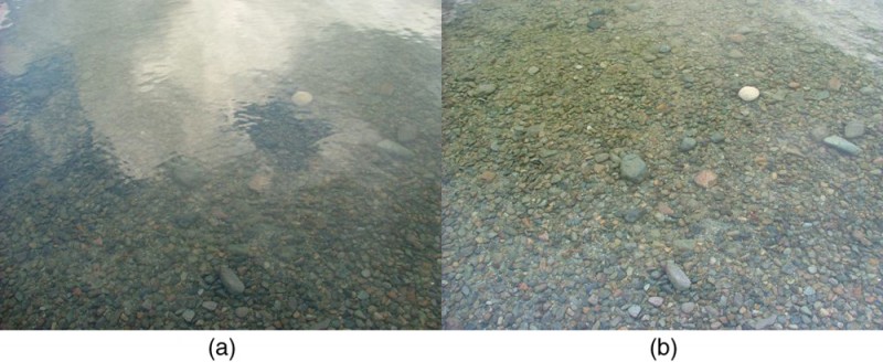
Figure 1. These two photographs of a river show the effect of a polarizing filter in reducing glare in light reflected from the surface of water. Part (b) of this Figure was taken with a polarizing filter and part (a) was not. As a result, the reflection of clouds and sky observed in part (a) is not observed in part (b). Polarizing sunglasses are particularly useful on snow and water. (credit: Amithshs, Wikimedia Commons)
Illumination techniques comprise back lighting, diffuse (also known as full bright field) lighting, bright field (actually partial bright field or directional) lighting, and dark field lighting.
When you have accumulated and analyzed the information from these areas, with respect to the specific sample and inspection requirements, you can achieve the primary goal of machine vision lighting analysis—to provide sample-appropriate lighting that meets three acceptance criteria consistently:
When the intensity is reduced by 90.0%, it is 10.0% or 0.100 times its original value. That is, I = 0.100I0. Using this information, the equation I = I0 cos2 θ can be used to solve for the needed angle.
Find Polaroid sunglasses and rotate one while holding the other still and look at different surfaces and objects. Explain your observations. What is the difference in angle from when you see a maximum intensity to when you see a minimum intensity? Find a reflective glass surface and do the same. At what angle does the glass need to be oriented to give minimum glare?
Figure 5. The left image shows nyloc nuts with a UV ring light, but flooded with red 660 nm “ambient” light. The goal is to determine nylon presence/absence. Given the large ambient contribution, it is difficult to get sufficient contrast from the relatively low-yield blue fluoresced light from the sample. The right image has the same lighting, except a 510 nm short pass filter was installed on the camera lens, effectively blocking the red “ambient” light and allowing the blue 450 nm light to pass.
Figure 22 illustrates potential application fields for the different lighting techniques based on the two most prevalent gross surface characteristics: (1) surface flatness and texture and (2) surface reflectivity.
Figure 6. On the left, the bottom of a soda can is illuminated with a bright field ring light but shows poor contrast, uneven lighting, and specular reflections. On the right, the soda can is imaged with diffuse light, creating an even background so the code can be read.
Figure 5. A polarizing filter has a polarization axis that acts as a slit passing through electric fields parallel to its direction. The direction of polarization of an EM wave is defined to be the direction of its electric field.
Figure 10 illustrates how the component of the electric field parallel to the long molecules is absorbed. An electromagnetic wave is composed of oscillating electric and magnetic fields. The electric field is strong compared with the magnetic field and is more effective in exerting force on charges in the molecules. The most affected charged particles are the electrons in the molecules, since electron masses are small. If the electron is forced to oscillate, it can absorb energy from the EM wave. This reduces the fields in the wave and, hence, reduces its intensity. In long molecules, electrons can more easily oscillate parallel to the molecule than in the perpendicular direction. The electrons are bound to the molecule and are more restricted in their movement perpendicular to the molecule. Thus, the electrons can absorb EM waves that have a component of their electric field parallel to the molecule. The electrons are much less responsive to electric fields perpendicular to the molecule and will allow those fields to pass. Thus the axis of the polarizing filter is perpendicular to the length of the molecule.
BELLlighting
Figure 1. The cellophane wrappers on packs of note cards shows the left meets all three acceptance criteria whereas the right meets only criteria one and two. In this circumstance, the wrinkles are not precluding a good barcode reading. But what if the wrinkles were in a different place in the next pack on the line?

Figure 6. The effect of rotating two polarizing filters, where the first polarizes the light. (a) All of the polarized light is passed by the second polarizing filter, because its axis is parallel to the first. (b) As the second is rotated, only part of the light is passed. (c) When the second is perpendicular to the first, no light is passed. (d) In this photograph, a polarizing filter is placed above two others. Its axis is perpendicular to the filter on the right (dark area) and parallel to the filter on the left (lighter area). (credit: P.P. Urone)
Figure 11. The motor oil bottle on the left is illuminated with a red 660 nm ring light. On the right, the bottle is illuminated with a 360 nm UV fluorescent light.
Light reflected at these angles could be completely blocked by a good polarizing filter held with its axis vertical. Brewster’s angle for water and air are similar to those for glass and air, so that sunglasses are equally effective for light reflected from either water or glass under similar circumstances. Light not reflected is refracted into these media. So at an incident angle equal to Brewster’s angle, the refracted light will be slightly polarized vertically. It will not be completely polarized vertically, because only a small fraction of the incident light is reflected, and so a significant amount of horizontally polarized light is refracted.
This diagram plots surface reflectivity, divided into three categories—matte, mirror, and mixed—versus surface flatness and texture or topography. As you move right and downward on the diagram, more specialized lighting geometries and structured lighting types are necessary.
Fully understanding the immediate inspection area’s physical requirements and limitations, in a 3D space, is critical. In particular, depending on the specific inspection requirements, the use of robotic pick-and-place machines or pre-existing, but necessary, support structures, may severely limit the choice of effective lighting solutions by forcing a compromise in not only the type of lighting but also its geometry, working distance, intensity, and pattern. For example, you may determine that a diffuse light source is required but cannot be applied because of limited close-up, top-down access. Inspection on high-speed lines may require intense continuous light or a strobe light to freeze motion, and of course large objects present an altogether different challenge for lighting. Additionally, consistent part placement and presentation are also important, particularly depending on which features are being inspected; however, even lighting for inconsistencies in part placement and presentation can be developed, as a last resort, if fully understood.
illuminate is New England's premier source for lighting and controls offering a wide variety of innovative products and unparalleled customer support.
Since the part of the light that is not reflected is refracted, the amount of polarization depends on the indices of refraction of the media involved. It can be shown that reflected light is completely polarized at a angle of reflection θb, given by [latex]\tan\theta_{\text{b}}=\frac{n_2}{n_1}\\[/latex], where n1 is the medium in which the incident and reflected light travel and n2 is the index of refraction of the medium that forms the interface that reflects the light. This equation is known as Brewster’s law, and θb is known as Brewster’s angle, named after the 19th-century Scottish physicist who discovered them.
Edmund Optics has been a leading producer of optics, imaging, and laser optics for 80 years. Discover the latest optical and imaging technology.
The lighting sources now commonly used in machine vision are fluorescent, quartz halogen, LED, metal halide (mercury), and xenon.
IR light is considerably more effective at penetrating polymer materials than the short wavelengths, such as UV or blue, and even red in some cases (see Figure 13). Conversely, it is this lack of penetration depth that makes blue light more useful for imaging shallow surface features of black rubber compounds or laser etchings, for instance.
Only the component of the EM wave parallel to the axis of a filter is passed. Let us call the angle between the direction of polarization and the axis of a filter θ. If the electric field has an amplitude E, then the transmitted part of the wave has an amplitude E cos θ (see Figure 7). Since the intensity of a wave is proportional to its amplitude squared, the intensity I of the transmitted wave is related to the incident wave by I = I0 cos2 θ, where I0 is the intensity of the polarized wave before passing through the filter. (The above equation is known as Malus’s law.)
Light is one type of electromagnetic (EM) wave. As noted earlier, EM waves are transverse waves consisting of varying electric and magnetic fields that oscillate perpendicular to the direction of propagation (see Figure 2). There are specific directions for the oscillations of the electric and magnetic fields. Polarization is the attribute that a wave’s oscillations have a definite direction relative to the direction of propagation of the wave. (This is not the same type of polarization as that discussed for the separation of charges.) Waves having such a direction are said to be polarized. For an EM wave, we define the direction of polarization to be the direction parallel to the electric field. Thus we can think of the electric field arrows as showing the direction of polarization, as in Figure 2.
Polarizing filters have a polarization axis that acts as a slit. This slit passes electromagnetic waves (often visible light) that have an electric field parallel to the axis. This is accomplished with long molecules aligned perpendicular to the axis as shown in Figure 9.
All we need to solve these problems are the indices of refraction. Air has n1 = 1.00, water has n2 = 1.333, and crown glass has n′2=1.520. The equation [latex]\tan\theta_{\text{b}}=\frac{n_2}{n_1}\\[/latex] can be directly applied to find θb in each case.
Figure 7. The 2D dot peen matrix code on the left is illuminated by bright field ring light. The right is imaged with a low angle linear dark field light. A simple change in light pattern creates a more effective and robust inspection.
In flat screen LCD televisions, there is a large light at the back of the TV. The light travels to the front screen through millions of tiny units called pixels (picture elements). One of these is shown in Figure 12 (a) and (b). Each unit has three cells, with red, blue, or green filters, each controlled independently. When the voltage across a liquid crystal is switched off, the liquid crystal passes the light through the particular filter. One can vary the picture contrast by varying the strength of the voltage applied to the liquid crystal.
Figure 14. On the left, a transparent plastic six-pack can holder is shown with a red back light. The right shows the same, except for the addition of a polarizer pair, showing stress fields in the polymer.
To achieve a deep, rich and expansive DOF, you'll want to set the f-stop to around f/11 or higher. You may have seen this principle demonstrated when you look ...
How a sample’s surface interacts with task-specific and ambient light is related to many factors, including the gross surface shape, geometry, and reflectivity as well as its composition, topography, and color. Some combination of these factors determines how much light, and in what manner, is reflected to the camera, and subsequently available for acquisition, processing, and measurement. For example, a curved, specular surface, such as the bottom of a soda can (Figure 6), reflects a directional light source differently from a flat, diffuse surface such as copy paper. Similarly, a topographic surface, such as a populated PCB, reflects differently from a flat but finely textured or dimpled (Figure 7) surface, depending on the light type and geometry.
The following sequence of lighting analysis assumes a working knowledge of lighting types, camera sensitivities, and optics and familiarity with illumination techniques and the four cornerstones of vision illumination. You can use it as a checklist, but it is by no means comprehensive. It does, however, provide a good working foundation for a standardized method that you can modify and/or expand for the inspection’s requirements.
If you hold your Polaroid sunglasses in front of you and rotate them while looking at blue sky, you will see the sky get bright and dim. This is a clear indication that light scattered by air is partially polarized. Figure 11 helps illustrate how this happens. Since light is a transverse EM wave, it vibrates the electrons of air molecules perpendicular to the direction it is traveling. The electrons then radiate like small antennae. Since they are oscillating perpendicular to the direction of the light ray, they produce EM radiation that is polarized perpendicular to the direction of the ray. When viewing the light along a line perpendicular to the original ray, as in Figure 11, there can be no polarization in the scattered light parallel to the original ray, because that would require the original ray to be a longitudinal wave. Along other directions, a component of the other polarization can be projected along the line of sight, and the scattered light will only be partially polarized. Furthermore, multiple scattering can bring light to your eyes from other directions and can contain different polarizations.
In those applications requiring high light intensity, such as high-speed inspections, it may be useful to match the source’s spectral output with the spectral sensitivity of your particular vision camera (Figure 4). For example, CMOS sensor-based cameras are more IR sensitive than their charge-coupled device (CCD) counterparts, imparting a significant sensitivity advantage in light-starved inspection settings when using IR LED or IR-rich Tungsten sources.
This article covers both custom optical elements and custom optical assemblies or systems – beginning with the former. Many optical elements such as lenses, ...
There are exceptions, however, to this general rule. For example, a 700 nm short pass filter, otherwise known as an IR blocker, is standard in color cameras because IR content can alter the color accuracy and balance, particularly of the green channel. Figure 5 illustrates how the use of a pass filter can block ambient light very effectively, particularly when the light of interest is low-yield fluorescence.
Led Circle Ring Light, online shopping Led Circle Ring Light, Retail Led Circle Ring Light from LightInTheBox.
This guide aims to present a standard method for developing sample-appropriate lighting rather than dwell on theoretical treatments. It details relevant aspects in a practical framework, with examples, where applicable, from the following areas:
Most manufacturers of vision lighting products also offer lights with various combinations of techniques available in the same light, and at least in the case of LED-based varieties, each of the techniques may be individually addressable. This circumstance allows for greater flexibility and also reduces potential costs when many different inspections can be accomplished in a single station rather than two. If the application conditions and limitations of each of these lighting techniques, as well as the intricacies of the inspection environment and sample/light interactions are well understood, it is possible to develop an effective lighting solution that meets the three acceptance criteria.
Historically, fluorescent and quartz halogen lighting sources have been used most commonly. In recent years, LED technology has improved in stability, intensity, and cost-effectiveness; however, it is still not as cost-effective for large area lighting, particularly compared with fluorescent sources. However, if application flexibility, output stability, and longevity are important parameters, then LED lighting might be more appropriate. Depending on the exact lighting requirements, oftentimes you can use more than one source type for a specific implementation, and most vision experts agree that one source type cannot adequately solve all lighting issues.
Figure 21. The peanut brittle bag on the left is under a bright field ring light. On the right, it is under a dark field ring light—note the seam is very visible.
The Sun and many other light sources produce waves that are randomly polarized (see Figure 4). Such light is said to be unpolarized because it is composed of many waves with all possible directions of polarization. Polaroid materials, invented by the founder of Polaroid Corporation, Edwin Land, act as a polarizing slit for light, allowing only polarization in one direction to pass through. Polarizing filters are composed of long molecules aligned in one direction. Thinking of the molecules as many slits, analogous to those for the oscillating ropes, we can understand why only light with a specific polarization can get through. The axis of a polarizing filter is the direction along which the filter passes the electric field of an EM wave (see Figure 5).
Figure 7. A polarizing filter transmits only the component of the wave parallel to its axis, , reducing the intensity of any light not polarized parallel to its axis.
Partial bright field lighting is the most commonly used vision lighting technique, and is the most familiar lighting used every day, including sunlight. This type of lighting is distinguished from full bright field in that it is directional, typically from a point source and, because of its directional nature, it is a good choice for generating contrast and enhancing topographic detail. It is much less effective, however when used on-axis with specular surfaces, generating the familiar “hotspot” reflection.
The following figures illustrate the differences in implementation and result of circular directional (partial bright field) and circular dark field lights on a mirrored surface.
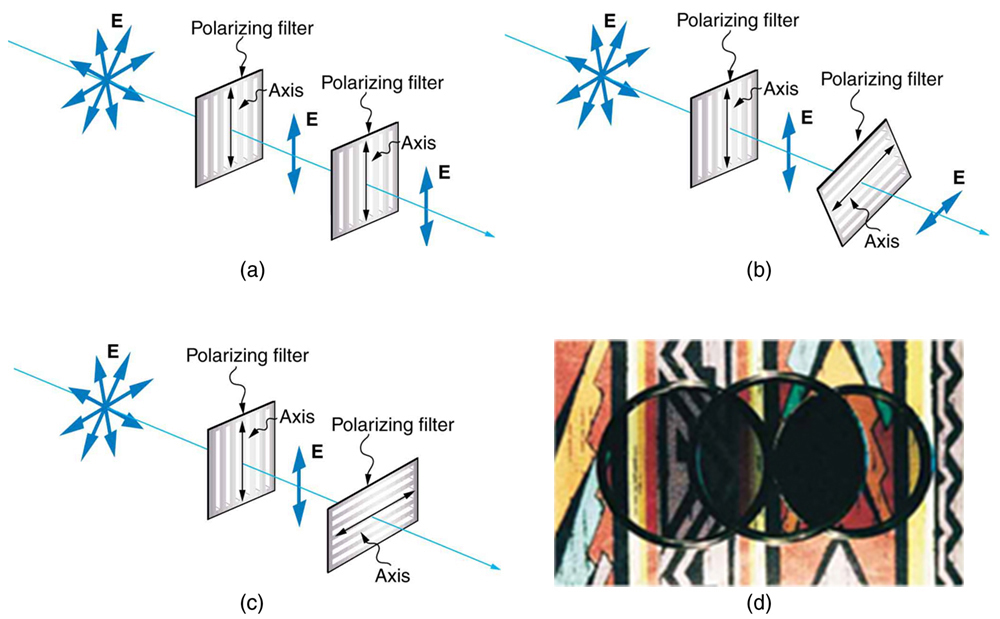
Figure 8 illustrates what happens when unpolarized light is reflected from a surface. Vertically polarized light is preferentially refracted at the surface, so that the reflected light is left more horizontally polarized. The reasons for this phenomenon are beyond the scope of this text, but a convenient mnemonic for remembering this is to imagine the polarization direction to be like an arrow. Vertical polarization would be like an arrow perpendicular to the surface and would be more likely to stick and not be reflected. Horizontal polarization is like an arrow bouncing on its side and would be more likely to be reflected. Sunglasses with vertical axes would then block more reflected light than unpolarized light from other sources.
Figure 13. In the populated PCB the penetration of red is 660 nm (left image) and IR 880 nm light. Notice the better penetration of IR despite the red blooming out from the hole in the top center of the board.
There is a range of optical effects used in sunglasses. Besides being Polaroid, other sunglasses have colored pigments embedded in them, while others use non-reflective or even reflective coatings. A recent development is photochromic lenses, which darken in the sunlight and become clear indoors. Photochromic lenses are embedded with organic microcrystalline molecules that change their properties when exposed to UV in sunlight, but become clear in artificial lighting with no UV.
Understanding how to manipulate and enhance sample contrast using the four cornerstones is crucial in meeting the three acceptance criteria for assessing the quality and robustness of lighting. Effecting contrast changes through geometry involves moving the sample, light, and/or camera positions until you find a suitable configuration. For example, a coaxial ring light (one mounted around the camera) may generate hotspot glare on a semireflective barcode surface, but by simply moving the light off-axis, the hotspot glare is also moved out of the camera’s view. Contrast changes through structure or the shape of the light projected on the sample is generally light head– or lighting technique–specific (see the Lighting Techniques section in Part 2 of this series). Contrast changes through color lighting are related to differential color absorbance versus reflectance (See Sample/Light Interaction).
Perhaps no other aspect of vision system design and implementation has consistently caused more delays, cost overruns, and general consternation than lighting. Historically, lighting often was the last aspect specified, developed, or funded, if at all. This approach was not entirely unwarranted, as until recently there was no real vision-specific lighting on the market, meaning lighting solutions typically consisted of standard incandescent or fluorescent consumer products, with various amounts of ambient contribution.
A fairly large angle between the direction of polarization and the filter axis is needed to reduce the intensity to 10.0% of its original value. This seems reasonable based on experimenting with polarizing films. It is interesting that, at an angle of 45º, the intensity is reduced to 50% of its original value (as you will show in this section’s Problems & Exercises). Note that 71.6º is 18.4º from reducing the intensity to zero, and that at an angle of 18.4º the intensity is reduced to 90.0% of its original value (as you will also show in Problems & Exercises), giving evidence of symmetry.
Figure 22. Lighting Technique Application Fields: Surface Shape Versus Surface Reflectivity Detail (Although not shown, any light technique is generally effective in the Geometry Independent Area of the diagram.)
With respect to the lighting environment, there are two aspects to evaluate when determining the optimal lighting solution: (1) immediate inspection environment and (2) sample/light interaction
Figure 3. The transverse oscillations in one rope are in a vertical plane, and those in the other rope are in a horizontal plane. The first is said to be vertically polarized, and the other is said to be horizontally polarized. Vertical slits pass vertically polarized waves and block horizontally polarized waves.
Another interesting phenomenon associated with polarized light is the ability of some crystals to split an unpolarized beam of light into two. Such crystals are said to be birefringent (see Figure 15). Each of the separated rays has a specific polarization. One behaves normally and is called the ordinary ray, whereas the other does not obey Snell’s law and is called the extraordinary ray. Birefringent crystals can be used to produce polarized beams from unpolarized light. Some birefringent materials preferentially absorb one of the polarizations. These materials are called dichroic and can produce polarization by this preferential absorption. This is fundamentally how polarizing filters and other polarizers work. The interested reader is invited to further pursue the numerous properties of materials related to polarization.
Many crystals and solutions rotate the plane of polarization of light passing through them. Such substances are said to be optically active. Examples include sugar water, insulin, and collagen (see Figure 13). In addition to depending on the type of substance, the amount and direction of rotation depends on a number of factors. Among these is the concentration of the substance, the distance the light travels through it, and the wavelength of light. Optical activity is due to the asymmetric shape of molecules in the substance, such as being helical. Measurements of the rotation of polarized light passing through substances can thus be used to measure concentrations, a standard technique for sugars. It can also give information on the shapes of molecules, such as proteins, and factors that affect their shapes, such as temperature and pH.
Polarizing filters, when applied in pairs, one between the light and sample and the other between the sample and camera, and typically affixed to the lens through screw threads, are useful for detecting structural lattice damage in otherwise transparent samples (Figure 14).
Brewster’s angle: [latex]{\theta }_{\text{b}}={\tan}^{-1}\left(\frac{{n}_{2}}{{n}_{1}}\right)\\[/latex], where n2 is the index of refraction of the medium from which the light is reflected and n1 is the index of refraction of the medium in which the reflected light travels
This level of in-depth analysis can and often does result in seemingly contradictory directions, and a compromise is necessary. For example, detailed sample/light interaction analysis might point to the use of the dark field lighting technique, but the inspection environment analysis indicates that the light must be remote from the part. In this instance, a more intense linear bar light(s) oriented in dark field configuration may create the contrast you want, but perhaps require more image post-processing.


 Ms.Cici
 8618319014500