
Tutorial 18 - Diffuse Lighting - diffuse illumination
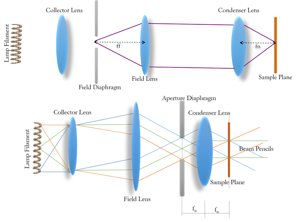
Figure 3: In the top panel, as the aperture is opened or closed, the illuminated area on the sample also changes. In the bottom panel, closing the aperture allows a greater range of angular illumination to the sample with more, or fewer, points of the light source contributing to the illumination field at the sample. Drawings are taken from the Lenstotek.com Köhler webpage
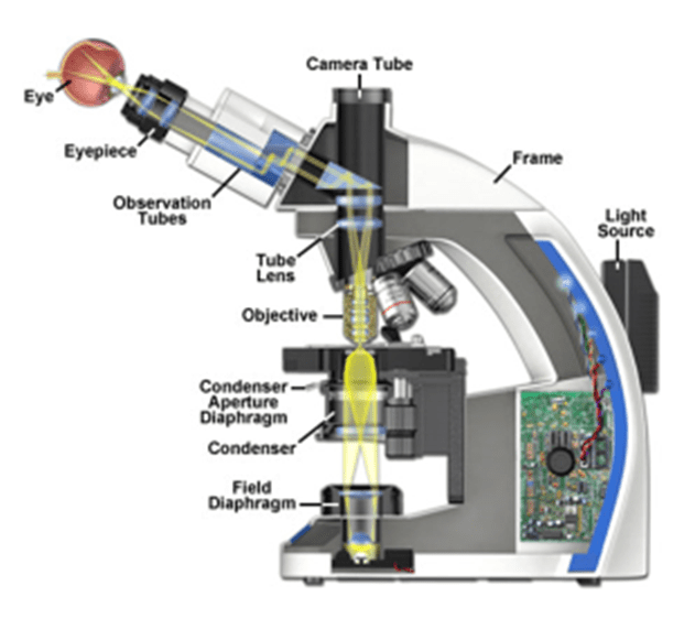
Figure 4: Location of various microscope components used to adjust Köhler illumination for an upright microscope. Light is generated at the base, below the field diaphragm. The condenser lens and aperture diaphragm are commonly located close to the sample and has adjusting screws to allow the centering of the lens. The figure is taken from the Zeiss.com Optical Train webpage.
Illuminationof light formula
ledlineline ... Photo by LedLine Line on December 13, 2024. May be an image of socket. Super lançamento LED LINE ...
What isilluminationin the Bible
Setting up Köhler illumination becomes second nature with practice. One common condition can confound most beginners and even some experts is the adjustment of the aperture diaphragm. The appropriate size to match a low magnification low NA lens may be sufficiently closed to essentially extinguish all light transmittance through higher NA, usually high magnification lenses. It is, therefore, a good idea to check the aperture diaphragm when changing to higher NA objectives.
Light from a point on the left (the light source filament in Fig.1) expands in all directions. If emitted at a distance from the lens equal to the lens focal length, it is organized to a collection of parallel rays upon exiting the lens. While only the direct, central ray and a large angle ray are illustrated, every ray in the collection angle of the lens behaves similarly.
With this additional lens in place, one can see the different points from the illumination source, as illustrated by the red, green and blue lines in Fig.2. This means that the same region of the sample is illuminated from different angles, scrambling the filament/light source structure. This means that the illumination of the sample will be highly uniform and free of any structures from the light source.
The predecessor to Köhler illumination was critical illumination . This method used two lenses as discussed above to produce a magnified image of the light source at the sample plane. This provided effective illumination, however, an image of the light source was superimposed over the sample. Köhler's innovation was to add an additional lens to the illumination light path, which converts the image into parallel propagating light waves, with visible structure no longer recognizable.
Types ofilluminationPDF
The need for Köhler illumination, and the mechanism by which it is achieved, are best understood through seeing a microscope as a series of simple lenses. This article will introduce the behavior of a simple lens, and then explore the mechanism, optics and common practice of Köhler illumination.
Köhler's optical design also allows for the control of: the illumination field of view, the power delivered to the sample, and the effective illumination numerical aperture (NA).
Köhler, August (1893). "Ein neues Beleuchtungsverfahren für mikrophotographische Zwecke". Zeitschrift für wissenschaftliche Mikroskopie und für Mikroskopische Technik. 10 (4): 433-440.
In transmission imaging, the components of Köhler illumination are more adjustable and therefore more likely to need correction with everyday microscope use. A common approach is presented below, with some reference to the underlying optical considerations presented. An illustration of the location of the various components on an example upright microscope is illustrated in Fig.4.
Koehler, August (1894). "New Method of Illumination for Photomicrographical Purposes". Journal of the Royal Microscopical Society. 14: 261-262.
When propagating as parallel rays, the image of the object on the left would not be visible were we to observe those rays. The effect of this is that the image will be blurred and mixed , and structural information about the object (i.e. the details in a biological sample, or the filament in a lamp bulb) will be unrecognizable. To restore the parallel rays to a real image, a second lens must re-focus the parallel rays onto a second plane.
Köhler illumination is critical to removing illumination source structure from the image of the sample. The correct application of Köhler illumination provides the best possible contrast in both brightfield, phase contrast, and fluorescence techniques.
For us it's the norm to draw from our 20 plus years of technical know how and experience with designers to come up with answers to lighting problems. We use the ...
Types ofilluminationin slit lamp
In microscopy, we aim to produce a sharply-defined, magnified image of our sample in our detector or our eyes. The sample requires illumination for us to see it – but how do we avoid simply seeing a sharply-defined, magnified image of the LED, bulb filament or arc lamp of our light source? Instead, we require even, uniform illumination of our sample, free from structures and patterns, no matter what light source we use. The optical method for achieving this was invented by August Köhler (Köhler 1893). This method, called Köhler illumination, underlies the common modern illumination methods in brightfield, phase contrast, darkfield and epifluorescence imaging.
Zeiss.com webpage on the basic optical train of a microscope http://zeiss-campus.magnet.fsu.edu/articles/basics/opticaltrain.html
Illuminationlighting design
Figure 1: Converging rays from the focal plane on the left emerge as parallel rays on the right. Light-emitting from the central point of the filament is imaged through the lens as light field traveling along the optical center, as illustrated in green. In contrast, a point displaced from the optical center, illustrated in blue, also exits the lens as a light field, but in a different direction. The lens focal length is indicated by f.
Control of the illumination field of view is obtained by placing an adjustable aperture in the light path to the left of the field lens, as demonstrated in Fig.3. An image of the diaphragm is transmitted by the field and condenser lens, with the image of the condenser formed at the sample 4 focal lengths (4f) away. This 4f optical configuration underlies modern infinity-corrected microscopes.
LEDilluminationlights
This International Standard provides requirements to perform reproducible photometric and colorimetric measurements on road illumination devices.
Circle ofillumination
In addition, placing this aperture to the left of the condenser lens allows control of the range of angles being transmitted to the sample, thus controlling the NA and the resolution. It also controls the ight density / power within the field of view, as opening or closing the aperture blocks or allows light from positions farther from the center of the light source. Fig.3 illustrates the function of the aperture.
At its simplest, a microscope may be seen as a series of simple (aberration/defect-free) lenses. The behavior of a single lens is illustrated in Fig.1.

The 10-inch diameter ring light features an adjustable color temperature and LED brightness setting to suit your space and preferred lighting, with a holder at ...
Figure 2: Optical diagram of lens configuration in Köhler illumination. The lamp filament on the left emits light in all directions. The red, green and blue paths illustrate the paths of light emitted from three different points on the filament. The collector lens, placed a focal length fc in front of the filament, sends the three different rays towards the field lens at different angles. The field lens focuses the three light rays to a region at its focal length, ff. ff on the other side is also fn away from the condenser lens. The condenser lens transforms any structure at fn existing to the left of the condenser lens into uniform illumination at position fn on the right side of the condenser lens, where the sample is placed. The optical drawing was taken from the Lenstrotek.com article on Köhler illumination.
Shop B&H for our huge inventory of Ring Lights from top brands like Yongnuo, Reflecmedia, Neewer and Godox. Explore our unbeatable selection.
Ruffwear Web Master · Ruffwear Front Range · Ruffwear Hi & Light · Final Review: Should You Buy a Ruffwear Harness? · How We Chose · Further Reading ...
Illuminationlighting meaning
20151214 — Below is a short list of my three favorite practical lighting sources, and how to use them most effectively.
Double Wide Bar, Dallas: See 14 unbiased reviews of Double Wide Bar, rated 4.5 of 5 on Tripadvisor and ranked #971 of 2314 restaurants in Dallas.
SOLAR VISION the UK's leading company for 100% solar powered external lighting and CCTV. Our product range offers the highest quality of solar street ...
Immerse yourself in the conversations with characters that range or the ordinary to the extraordinary. Pick one and venture into the unknown! ... BALA AI is ...
Most microscopes can be used in either transmission/trans-fluorescence mode, where the light travels through from the light source through the sample to the eye or camera, or in reflectance/epi-fluorescence mode where the light delivered through the objective follows the same path back before being deviated off to the eye or camera. For typical microscopes, Köhler illumination setup is not adjustable in the epi-fluorescence path, with the exception of centering the light source and its reflection within the optical plane.
Conversely, the aperture diaphragm can be opened too wide, but this is less likely to cause problems given the high-quality engineering of the light paths in modern microscopes. This can allow stray light rays from unexpected directions to illuminate the sample and reduce contrast or introduce glare.


 Ms.Cici
 8618319014500